US1855056A - Differential - Google Patents
Differential Download PDFInfo
- Publication number
- US1855056A US1855056A US510560A US51056031A US1855056A US 1855056 A US1855056 A US 1855056A US 510560 A US510560 A US 510560A US 51056031 A US51056031 A US 51056031A US 1855056 A US1855056 A US 1855056A
- Authority
- US
- United States
- Prior art keywords
- driven
- driving
- elements
- shafts
- cage
- Prior art date
- Legal status (The legal status is an assumption and is not a legal conclusion. Google has not performed a legal analysis and makes no representation as to the accuracy of the status listed.)
- Expired - Lifetime
Links
- 238000005096 rolling process Methods 0.000 description 3
- 230000005540 biological transmission Effects 0.000 description 2
- 101150109517 Camlg gene Proteins 0.000 description 1
- 101100379079 Emericella variicolor andA gene Proteins 0.000 description 1
- 230000004048 modification Effects 0.000 description 1
- 238000012986 modification Methods 0.000 description 1
- 230000002093 peripheral effect Effects 0.000 description 1
- 230000001105 regulatory effect Effects 0.000 description 1
Images


Classifications
-
- F—MECHANICAL ENGINEERING; LIGHTING; HEATING; WEAPONS; BLASTING
- F16—ENGINEERING ELEMENTS AND UNITS; GENERAL MEASURES FOR PRODUCING AND MAINTAINING EFFECTIVE FUNCTIONING OF MACHINES OR INSTALLATIONS; THERMAL INSULATION IN GENERAL
- F16H—GEARING
- F16H48/00—Differential gearings
- F16H48/20—Arrangements for suppressing or influencing the differential action, e.g. locking devices
- F16H48/30—Arrangements for suppressing or influencing the differential action, e.g. locking devices using externally-actuatable means
-
- F—MECHANICAL ENGINEERING; LIGHTING; HEATING; WEAPONS; BLASTING
- F16—ENGINEERING ELEMENTS AND UNITS; GENERAL MEASURES FOR PRODUCING AND MAINTAINING EFFECTIVE FUNCTIONING OF MACHINES OR INSTALLATIONS; THERMAL INSULATION IN GENERAL
- F16D—COUPLINGS FOR TRANSMITTING ROTATION; CLUTCHES; BRAKES
- F16D41/00—Freewheels or freewheel clutches
- F16D41/06—Freewheels or freewheel clutches with intermediate wedging coupling members between an inner and an outer surface
- F16D41/08—Freewheels or freewheel clutches with intermediate wedging coupling members between an inner and an outer surface with provision for altering the freewheeling action
- F16D41/10—Freewheels or freewheel clutches with intermediate wedging coupling members between an inner and an outer surface with provision for altering the freewheeling action with self-actuated reversing
- F16D41/105—Freewheels or freewheel clutches with intermediate wedging coupling members between an inner and an outer surface with provision for altering the freewheeling action with self-actuated reversing the intermediate members being of circular cross-section, of only one size and wedging by rolling movement not having an axial component between inner and outer races, one of which is cylindrical
-
- F—MECHANICAL ENGINEERING; LIGHTING; HEATING; WEAPONS; BLASTING
- F16—ENGINEERING ELEMENTS AND UNITS; GENERAL MEASURES FOR PRODUCING AND MAINTAINING EFFECTIVE FUNCTIONING OF MACHINES OR INSTALLATIONS; THERMAL INSULATION IN GENERAL
- F16H—GEARING
- F16H48/00—Differential gearings
- F16H48/12—Differential gearings without gears having orbital motion
- F16H48/16—Differential gearings without gears having orbital motion with freewheels
-
- F—MECHANICAL ENGINEERING; LIGHTING; HEATING; WEAPONS; BLASTING
- F16—ENGINEERING ELEMENTS AND UNITS; GENERAL MEASURES FOR PRODUCING AND MAINTAINING EFFECTIVE FUNCTIONING OF MACHINES OR INSTALLATIONS; THERMAL INSULATION IN GENERAL
- F16H—GEARING
- F16H48/00—Differential gearings
- F16H48/20—Arrangements for suppressing or influencing the differential action, e.g. locking devices
- F16H2048/204—Control of arrangements for suppressing differential actions
-
- F—MECHANICAL ENGINEERING; LIGHTING; HEATING; WEAPONS; BLASTING
- F16—ENGINEERING ELEMENTS AND UNITS; GENERAL MEASURES FOR PRODUCING AND MAINTAINING EFFECTIVE FUNCTIONING OF MACHINES OR INSTALLATIONS; THERMAL INSULATION IN GENERAL
- F16H—GEARING
- F16H48/00—Differential gearings
- F16H48/20—Arrangements for suppressing or influencing the differential action, e.g. locking devices
- F16H48/30—Arrangements for suppressing or influencing the differential action, e.g. locking devices using externally-actuatable means
- F16H2048/305—Arrangements for suppressing or influencing the differential action, e.g. locking devices using externally-actuatable means using manual actuators
-
- F—MECHANICAL ENGINEERING; LIGHTING; HEATING; WEAPONS; BLASTING
- F16—ENGINEERING ELEMENTS AND UNITS; GENERAL MEASURES FOR PRODUCING AND MAINTAINING EFFECTIVE FUNCTIONING OF MACHINES OR INSTALLATIONS; THERMAL INSULATION IN GENERAL
- F16H—GEARING
- F16H48/00—Differential gearings
- F16H48/12—Differential gearings without gears having orbital motion
-
- Y—GENERAL TAGGING OF NEW TECHNOLOGICAL DEVELOPMENTS; GENERAL TAGGING OF CROSS-SECTIONAL TECHNOLOGIES SPANNING OVER SEVERAL SECTIONS OF THE IPC; TECHNICAL SUBJECTS COVERED BY FORMER USPC CROSS-REFERENCE ART COLLECTIONS [XRACs] AND DIGESTS
- Y10—TECHNICAL SUBJECTS COVERED BY FORMER USPC
- Y10T—TECHNICAL SUBJECTS COVERED BY FORMER US CLASSIFICATION
- Y10T74/00—Machine element or mechanism
- Y10T74/19—Gearing
- Y10T74/19005—Nonplanetary gearing differential type [e.g., gearless differentials]
Definitions
- This invention relates to an improvement in automobile free ⁇ rolling differential driving units, that will givelpositive power toV either drive wheel, even where one wheel li* may be in mud or on ice, whereaswiththe present type of differential ⁇ the ear 1s powerless in such a case.
- This unit will give free rolling in either forward or reverse direction.
- ffree rolll ing is meant that on down grades the engine slows to anidling speed, thereby saving nearly twentyl percent in operating costs, twenty.
- the device is so designed that .the operator ofthe car may, athis will, use eitherthe free rolling or positive drive, by means of a handcontrol.
- This device greatly reduces the hazard of skidding by means of the positivedrive to both ⁇ wheels,not as with the present type when one wheel meets an obstruction. or stops, the other must go twice as fast.
- Fig. 2 is a transverse sectional view on the line 2,-,2. ofFig. 1, with the housing omitted;
- Fig. 13 ijs a disassembled perspective view of the operative parts of the differential;
- Fig: 4 is a sectional view through Oneofth. ⁇ .cam rings; s
- Fig. 5 is a side elevation of one of the4 roller cages
- Fig. 6 is a horizontal sectional view through the differential, showing the driven elementsu being operated automatically;
- Fig. 7 is a. cross-sectional view on the-line' 7-.7 of Fig. 6, with ⁇ the housing omitted;y
- Fig. 8 is a disassembled.perspective view: ofthe operative parts of fthe' differential shown in Fig. 6;
- Fig, v9. isa side elevation of oneof the camrings.
- Fig. 1() is a side elevation vof one of the ⁇ roller cages.4
- the numeral 1 designates the main drive. shaft mounted in bearings. 2 in a differential housing.
- ⁇ Axle housings 4 are'connectedv at opposite sides of the diferentialhousing. and enclose axles 5, which are adapted to.- ⁇ be attached'to the wheels ofthe vehicle'for driving the same.
- a bevel pinion 6 is Xed tothe drive shaft- 1 and meshes1 with a beveled gear 7 for trans.. mitting power to. both of the alignedaxles 5.
- the gear 7 has a reduced portion @Lat4 oneside of vwhich a shoulder 9 .is Vformed for receiving a positive drive ring 10.
- On: the opposite sides ofr the reduced portion8 are a plurality of lcam rings 11,12, 13 and 14,- arranged in alignment with each other, and co-.axially, and on the outer sidesfof theposif ⁇ Y tive drive ring 10 and the camfrings 1h144 areheadsl, all of which are held together and to the reduced portion 8 of the gear 7 by bolts 16, which pass therethrough as shown in Fig. 1. f
- the heads 15 are journaled in bearings 17' in the housing 3, forrotaryamovement with the gear 7.
- the cam rings 114-14 are each provided with angular cam surfaces in the inner face thereof, the rings 11 and 13 have4 -y ing cam surfacesv 18 turned in one direction Fig. 1 1s a horizontal sectional viewthrough while the cam rings 12 and V14 have angular 5' caml surfaces 19 turned in the opposite di-.f rection,as is clearly shown in Figs. 2 and 4.
- Rollers 2O engageV the cam surfaces 181and 19, and these rollers 20-are carried in slots.
- rollers 20 are adapted to cooperate with sliding drivers 23 and 24, each keyed or splined on the inner end of one of the axles the peripheral surfaces of the drivf ers 23 and 24 are round as shown inFig. 2,
- rollers 2O are wedged yinto grip engagement between the surfaces of thedrivers 23V ⁇ and 24 vandthe angular cam surfaces 18 or 19, according to the disposition of the drivers 23 and 24 within the cam rings 1'1-14.V
- the sliding driver 23- has a 4flange 25 on one side thereof in alignment with a flange 26 projecting from one side of the driver 24, whichlanges 25 and 26 are held together by Ya clamp 27.
- Akflange 28 projects from the opposite side ofthe driver 24 and is secured to a flange 29 formed on a sleeve 30 by means of a clamp 31.
- the sleeve 30 surrounds one .of the axles 5. and between said axlel and the hub of the head 15.
- the outer end of the sleeve 30 has a groove 32 formed therein for receivringa yoke 33-mounted on a pin 34, which is provided with an arm 35111 position to be engaged b-y a rod 36 for operating the same, which rod may extend' toy a suitablel control lever or to thetransmission of the vehicle in order to be automatically controlled
- the positive drive ring 10 has angular cam surfaces 37 therein turned in the opposite d1- rection from the cam surfaces in the ring 11 and are beveled to receive rollers 38 carried by roller cages 39, whichrollers are inclined outwardly, as shown in Fig..
- sliding Vcollar 48 has lugs 49 which en.-v gage the iiange ⁇ 28 of the driver- 24, and this collar 48 is engaged by a plate50 slidable lengthwise of the hub 51, but held against rotation by Ia flange 52 in the housing 3, as shown in Fig. 6, in' notch 57 in plate 50, as shown in Fig. 8.
- A' spring 53 is interposed between the hub 51 and sliding collar 48 for normally tending to move the collar and the sliding'driversv in one direction.
- Aplate '54' is connected with the cage by the bolts 16 and' may be regulated according to the relative disposition of the rollers from the axis.
- a differential the combination of aligned driven shafts, a driven element for driving each of said shafts and shiftable longitudinally thereof, a cage surrounding said driven elements and for driving the same, and roller clutch means between the cage and said driven elements for driving each of said driven elements in different directions when shifted to different positions.
- a differential he combination of aligned driven shafts, a driven element for driving each of said shafts and shiftable longitudinally thereof, a cage surrounding said driven elements and for driving the same, roller clutch means between the cage and said driven elements for driving each of said driven elements in different directions when shifted to different positions, and means for shifting said driven elements to different positions relative to the cage to be driven in different directions.
- a power transmitting unit one or more driving elements, one or more driven elements arranged coaxially of said driving elements, roller clutch means between the driving and driven elements for transmitting movement therebetween in different directions when in different positions relative to the driving elements, and means for causing shifting movement longitudinally of the axis of said elements.
- one or more driving elements a plurality of driven elements arranged coaxially of said driving elements and adapted to cooperate with different portions of said driving elements upon relative longitudinal movement, roller clutch means between the driving and driven elements for transmitting movement therebetween in dierent directions in different axial positions, and means for causing relative shifting movement of said elements longitudinally of the axis thereof.
- a driving cage a plurality of driven elements arranged coaxially within said cage and adapted to cooperate with different portions thereof upon relative longitudinal shifting movenient, roller clutch means between the cage and the driven elements for transmitting movement from the cage to ⁇ the driven elements f indifferent directions in different ⁇ axial positions, and means ,for causing rela-r tive shifting movement of the cageand driven elements longitudinally of the axis thereof.
- a driving cage a plurality7 of driven elements arranged coaxially within said cage yand adapted to bek operativelyconnected with different portions thereofV upon longitudinal shifting' movement, roller clutch means between the cage and ,the driven elements for transmitting movement from the cage to the driven4 elements iii opposite directions in different axial positions, ⁇ and means' for shifting ⁇ the driven elements longitudinally of Vthe axis driven elements, and haviiigcam surfaces.
- roller elements arranged in different directions, roller elements arranged in position to wedge in grip engagement between the cam surfaces andA the driven elements, and means for shifting the driven lelements longitudinally of the driven shafts to drive said shafts in different directions.
- a differential the combination of aligned driven shafts, a driven element for driving each of said shafts, a pluralityof cam rings surrounding and enclosing said driven elements, and having cam-surfaces arranged in different directions, roller cages associated with saidcam rings and having roller elements arranged in position to wedge in ⁇ grip engagement between the cam surfaces and the driven elements, means for securing the cam rings together against rela ⁇ tive movement, means for shifting the driven elements longitudinally of the driven shafts to drive said shafts in different directions, bevel gears fixed to the camrings, and a drive shaft operatively connected with said gears.
- a differential the combination of. aligned driven shafts, a driven element for driving each of said shafts, a plurality of cam rings surrounding and enclosing said driven elements, and having cam surfaces arranged in different directions, roller elements arranged in position to wedge in grip engagev ment between the cam surfaces and the driven elements, means for shifting the driven elements longitudinally of the driven shafts to drive said shafts in different directions, a positive drive ring fixed to said cam rings, rollers connected with said drive ring and having the contacting surfaces thereoftilted outwardly, a secondary driven element slidably fixed to at least one driven'shaft and in position to engage the last-mentioned rollers, and means for shifting said secondary driven element into wedging engagement with said rollers.
- a power transmitting unit the combination of driven shafts, one or more driven elements for driving saidshafts, a driving element for said driven elements, a secondary driven element fixed to at least one of the shafts, and a secondary driving element connected with the first-mentioned driving element for driving said secondary driven element.
- a power transmitting unit the combination of driven shafts, one or more driven elements forl driving both of said shafts, one or more driving elements for said driven elements, asecondary driven element fixed to one of the shafts, a secondary driving element ,for driving said secondary driven element,
- roller 'clutch means between the secondary driving and driven elements, and means for causing relative axial shifting movement between the secondary driving and driven elements to cause engagement of the roller clutch means.
Landscapes
- Engineering & Computer Science (AREA)
- General Engineering & Computer Science (AREA)
- Mechanical Engineering (AREA)
- Retarders (AREA)
Description
April 19, 1932. R. J. JoRoLEMoN DIFFERENTIAL Filed Jan. 22, 1931 4 Sheets-Sheet 1 April 19, 1932 l' R. J. JoRoLEMoN 1,855,056
` DIFFERENTIAL Filed Jan. 22, 1931 4 sheets-shew J2 4 Sheercs--She'e'ol 3 d IIIIIII QIIIIIII April 19, 1932. R. J. JoRoLEMoN' DIFFERENTIAL Filed Jan. 22, 1951 KK Nh. mh W April 119, 1932. R. J. JoRoLEMoN DIFFERENTIAL .who
Filed Jan. g2, 1951 4 Sheets-Sheet Patented Apr. 19, 1932 ROY J'. JBQQLEMON, 0F WASHINGTON, DISTRICT 0F COLUMBIA.
DHEEREN'HAL Application n led January 22, 1931. SerialiNo. 510,560,
This invention relates to an improvement in automobile free` rolling differential driving units, that will givelpositive power toV either drive wheel, even where one wheel li* may be in mud or on ice, whereaswiththe present type of differential `the ear 1s powerless in such a case. D
This unit will give free rolling in either forward or reverse direction. By ffree rolll ing is meant that on down grades the engine slows to anidling speed, thereby saving nearly twentyl percent in operating costs, twenty.
i is made through the present gear .shift lever.
The device is so designed that .the operator ofthe car may, athis will, use eitherthe free rolling or positive drive, by means of a handcontrol.
This device greatly reduces the hazard of skidding by means of the positivedrive to both` wheels,not as with the present type when one wheel meets an obstruction. or stops, the other must go twice as fast.
Vith the above and other objects in4 view, my invention consistsin the novel features and in the novel combination and arrangement of parts hereinafter -ully described, il- ,J lustrated in the accompanying drawingsl forming a part of this application and particularly pointed out the claims hereto'ap.- pende-df In the accompanying drawings.:
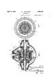
the dierential embodyingl this 'y invention;
Fig. 2 is a transverse sectional view on the line 2,-,2. ofFig. 1, with the housing omitted; Fig. 13 ijs a disassembled perspective view of the operative parts of the differential;
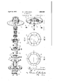
Fig: 4 is a sectional view through Oneofth.` .cam rings; s
Fig. 5 is a side elevation of one of the4 roller cages; f
Fig. 6is a horizontal sectional view through the differential, showing the driven elementsu being operated automatically;
Fig. 7 is a. cross-sectional view on the-line' 7-.7 of Fig. 6, with` the housing omitted;y
Fig. 8 is a disassembled.perspective view: ofthe operative parts of fthe' differential shown in Fig. 6;
Fig, v9. isa side elevation of oneof the camrings; and i.
Fig. 1() is a side elevation vof one of the` roller cages.4
The numeral 1 designates the main drive. shaft mounted in bearings. 2 in a differential housing. `Axle housings 4are'connectedv at opposite sides of the diferentialhousing. and enclose axles 5, which are adapted to.-` be attached'to the wheels ofthe vehicle'for driving the same.
A bevel pinion 6 is Xed tothe drive shaft- 1 and meshes1 with a beveled gear 7 for trans.. mitting power to. both of the alignedaxles 5. The gear 7 has a reduced portion @Lat4 oneside of vwhich a shoulder 9 .is Vformed for receiving a positive drive ring 10. On: the opposite sides ofr the reduced portion8 are a plurality of lcam rings 11,12, 13 and 14,- arranged in alignment with each other, and co-.axially, and on the outer sidesfof theposif` Y tive drive ring 10 and the camfrings 1h144 areheadsl, all of which are held together and to the reduced portion 8 of the gear 7 by bolts 16, which pass therethrough as shown in Fig. 1. f
The heads 15 are journaled in bearings 17' in the housing 3, forrotaryamovement with the gear 7. The cam rings 114-14 are each provided with angular cam surfaces in the inner face thereof, the rings 11 and 13 have4 -y ing cam surfacesv 18 turned in one direction Fig. 1 1s a horizontal sectional viewthrough while the cam rings 12 and V14 have angular 5' caml surfaces 19 turned in the opposite di-.f rection,as is clearly shown in Figs. 2 and 4. Rollers 2O engageV the cam surfaces 181and 19, and these rollers 20-are carried in slots.
21 formed inV roller cages 22, there being one mo roller cage on each side of each of the cam rings 11-14, and t-wo cages l22 between each two of the cam rings, as shown in Fig. 1.V
f The rollers 20 are adapted to cooperate with sliding drivers 23 and 24, each keyed or splined on the inner end of one of the axles the peripheral surfaces of the drivf ers 23 and 24 are round as shown inFig. 2,
so that the rollers 2O are wedged yinto grip engagement between the surfaces of thedrivers 23V` and 24 vandthe angular cam surfaces 18 or 19, according to the disposition of the drivers 23 and 24 within the cam rings 1'1-14.V
The sliding driver 23- has a 4flange 25 on one side thereof in alignment with a flange 26 projecting from one side of the driver 24, whichlanges 25 and 26 are held together by Ya clamp 27.
Akflange 28 projects from the opposite side ofthe driver 24 and is secured to a flange 29 formed on a sleeve 30 by means of a clamp 31. The sleeve 30 surrounds one .of the axles 5. and between said axlel and the hub of the head 15. The outer end of the sleeve 30 has a groove 32 formed therein for receivringa yoke 33-mounted on a pin 34, which is provided with an arm 35111 position to be engaged b-y a rod 36 for operating the same, which rod may extend' toy a suitablel control lever or to thetransmission of the vehicle in order to be automatically controlled The positive drive ring 10 has angular cam surfaces 37 therein turned in the opposite d1- rection from the cam surfaces in the ring 11 and are beveled to receive rollers 38 carried by roller cages 39, whichrollers are inclined outwardly, as shown in Fig.. 1, to be engaged by the beveled peripheralsurface 40 of the driving disk 41 mounted at the inner -end of a sleeve 42 which surrounds one of the axles 5 and between the hub ofthe head 15 and said axle. The outer end of the sleeve 42 has a groove 43'therein to be engagedby a yoke 44'connected with a pin 45 mounted in the housing 3, and which pin carries an arm 46 adapted to be controlled by a rod 47, whichv vthe axles 5 in one direction, as said cam rings are rotatedxfrom the drive shaft, by reason of the wedging engagement of the rollers 20y between the angular cam surfacesv and the peripheries of the drivers 23 and 24. When, however, the speedV ofthe wheels .and axles exceedsV the speed ofthe driving icageand' wheeling. f 1
back out of wedging engagement, and the wheels and raxles will roll free of the influen ce of the drive shaft, and without transmitting power to the drive shaft. This gives what is termed as free rolling7 or free When l the vehicle isv driven backward, it
'is necessary to shift the drivers 23 and 24 into engagement with the rollers `2O for the other two cam rings12and 14, which have their l angular cam surfaces turned in the opposite direction, so as to cause a wedging of the rollersbetween these angular cam surfaces and the peripheries of the drivers 23 and 24 when the vcage is driven in the opposite di-A rection by the drive shaft.
This is accomplished by the clamps 27 and.
31 which connect the drivers v23 and 24 together and to the sleeve 30, which sleeve is moved lengthwise of the axis y5 by the yoke.
33 as operated by the rod 35 which rod is preferably: connected with one end of the transmission reverse fork shaft.
Under somecircumstances, it is desirable to 'utilize the braking action of the vehicle engine on thewheels, and this is permitted by positively connecting the drivering 10 of the driving cage with the axle 5 through the disk 41, which'is moved into engagement with the inclined rollers 38 of the ring 10, bythe rod 47 which acts on the yoke 44 to slide the sleeve 42 inward and which, in turn, moves Y the disk 41. Thiswill connect the driving cage with the axle when cam rings 11 and 13 are disconnected by reason of the backward movement of the rollers 20 within the cam surfaces and* will thus allow the excess speed ofV theaxles to be transmitted toV the positions, engaging with the rollers 20 ofv rings 12 and l In the modification shown in Figs..6
8, the positively actuated sliding means for the disks 23 and 24 are omitted and provision` is made for automatically sliding these disks into engagement with the proper cam rings, according to the direction of rotation of the4 drive shaft 1.y c
sliding Vcollar 48 has lugs 49 which en.-v gage the iiange`28 of the driver- 24, and this collar 48 is engaged by a plate50 slidable lengthwise of the hub 51, but held against rotation by Ia flange 52 in the housing 3, as shown in Fig. 6, in' notch 57 in plate 50, as shown in Fig. 8. A' spring 53 is interposed between the hub 51 and sliding collar 48 for normally tending to move the collar and the sliding'driversv in one direction. Aplate '54' is connected with the cage by the bolts 16 and' may be regulated according to the relative disposition of the rollers from the axis.
In this way, when the drive shaft 1 is reversed, it will cause the plate 54 to act on the rollers to move them forward in the cam grooves '56, thus forcing the plate 60 backward against the tension of the spring'53 and thus sliding the drivers 23 and 24 into engagement with the rollers 2O for the cani rings 12 and 14. This sliding of the drivers is thus accomplished automatically and does not require a connection between the same and the transmission.
I claim:
1. In a differential, the combination of aligned driven shafts, a driven element for driving each of said shafts and shiftable longitudinally thereof, a cage surrounding said driven elements and for driving the same, and roller clutch means between the cage and said driven elements for driving each of said driven elements in different directions when shifted to different positions. Y
2. In a differential, he combination of aligned driven shafts, a driven element for driving each of said shafts and shiftable longitudinally thereof, a cage surrounding said driven elements and for driving the same, roller clutch means between the cage and said driven elements for driving each of said driven elements in different directions when shifted to different positions, and means for shifting said driven elements to different positions relative to the cage to be driven in different directions.
3. In a power transmitting unit, one or more driving elements, one or more driven elements arranged coaxially of said driving elements, roller clutch means between the driving and driven elements for transmitting movement therebetween in different directions when in different positions relative to the driving elements, and means for causing shifting movement longitudinally of the axis of said elements. Y
4. In a power transmitting unit, one or more driving elements, a plurality of driven elements arranged coaxially of said driving elements and adapted to cooperate with different portions of said driving elements upon relative longitudinal movement, roller clutch means between the driving and driven elements for transmitting movement therebetween in dierent directions in different axial positions, and means for causing relative shifting movement of said elements longitudinally of the axis thereof.
5. In a power transmitting unit, a driving cage, a plurality of driven elements arranged coaxially within said cage and adapted to cooperate with different portions thereof upon relative longitudinal shifting movenient, roller clutch means between the cage and the driven elements for transmitting movement from the cage to `the driven elements f indifferent directions in different` axial positions, and means ,for causing rela-r tive shifting movement of the cageand driven elements longitudinally of the axis thereof.y
6. In a power transmittingunit, a driving cage, a plurality7 of driven elements arranged coaxially within said cage yand adapted to bek operativelyconnected with different portions thereofV upon longitudinal shifting' movement, roller clutch means between the cage and ,the driven elements for transmitting movement from the cage to the driven4 elements iii opposite directions in different axial positions, `and means' for shifting `the driven elements longitudinally of Vthe axis driven elements, and haviiigcam surfaces.
arranged in different directions, roller elements arranged in position to wedge in grip engagement between the cam surfaces andA the driven elements, and means for shifting the driven lelements longitudinally of the driven shafts to drive said shafts in different directions.
8. In a differential, the combination of aligned driven shafts, a driven element for driving each of said shafts, a pluralityof cam rings surrounding and enclosing said driven elements, and having cam-surfaces arranged in different directions, roller cages associated with saidcam rings and having roller elements arranged in position to wedge in` grip engagement between the cam surfaces and the driven elements, means for securing the cam rings together against rela` tive movement, means for shifting the driven elements longitudinally of the driven shafts to drive said shafts in different directions, bevel gears fixed to the camrings, and a drive shaft operatively connected with said gears.
9. -In a differential, the combination of. aligned driven shafts, a driven element for driving each of said shafts, a plurality of cam rings surrounding and enclosing said driven elements, and having cam surfaces arranged in different directions, roller elements arranged in position to wedge in grip engagev ment between the cam surfaces and the driven elements, means for shifting the driven elements longitudinally of the driven shafts to drive said shafts in different directions, a positive drive ring fixed to said cam rings, rollers connected with said drive ring and having the contacting surfaces thereoftilted outwardly, a secondary driven element slidably fixed to at least one driven'shaft and in position to engage the last-mentioned rollers, and means for shifting said secondary driven element into wedging engagement with said rollers. v
10. In a power transmitting unit, the comioo ies
bination of a driving cage, one or more driven elements operatively connected therewith and adapted Vto be driven in dierent directions upon longitudinal movement relative tov the` cage, a sliding 'collar connected with the driven elements, a plate connected with said collar for actuating the saine, and cam actu-` ated means connected with the plate for automatically sliding'the drivenelements relative tothe cage.
1,14. In a power transmitting unit, the combination of driven shafts, one or more driven elements for driving saidshafts, a driving element for said driven elements, a secondary driven element fixed to at least one of the shafts, and a secondary driving element connected with the first-mentioned driving element for driving said secondary driven element.
l2. In a power transmitting unit, the co-ni- Y bination of driven shafts, one or more driven elements for driving both of said shafts, one
or more driving elements forsaid driven elements, ak secondary driven element fixed to one of the shafts, a secondary driving element n connected with the first-mentioned driving elements for driving said secondary driven element, and means for causing clutching engagement between the secondary driving and driven elements. Y
13. In a power transmitting unit, thecombination of driven shafts, one 'or more driven elements for driving both of said shafts, one or more driving elements for said driven elements, a secondary driven element fixed to one of the shafts, a secondary driving element for driving said secondary driven element, and roller clutch means between the secondary driving and driven elements.
14. In a power transmitting unit, the combination of driven shafts, one or more driven elements forl driving both of said shafts, one or more driving elements for said driven elements, asecondary driven element fixed to one of the shafts, a secondary driving element ,for driving said secondary driven element,
roller 'clutch means between the secondary driving and driven elements, and means for causing relative axial shifting movement between the secondary driving and driven elements to cause engagement of the roller clutch means. c
In testimony whereof I aflix my signature.
ROY J. JoRoLEMoN, l
Priority Applications (1)
| Application Number | Priority Date | Filing Date | Title |
|---|---|---|---|
| US510560A US1855056A (en) | 1931-01-22 | 1931-01-22 | Differential |
Applications Claiming Priority (1)
| Application Number | Priority Date | Filing Date | Title |
|---|---|---|---|
| US510560A US1855056A (en) | 1931-01-22 | 1931-01-22 | Differential |
Publications (1)
| Publication Number | Publication Date |
|---|---|
| US1855056A true US1855056A (en) | 1932-04-19 |
Family
ID=24031240
Family Applications (1)
| Application Number | Title | Priority Date | Filing Date |
|---|---|---|---|
| US510560A Expired - Lifetime US1855056A (en) | 1931-01-22 | 1931-01-22 | Differential |
Country Status (1)
| Country | Link |
|---|---|
| US (1) | US1855056A (en) |
Cited By (1)
| Publication number | Priority date | Publication date | Assignee | Title |
|---|---|---|---|---|
| US6860124B1 (en) * | 1999-10-04 | 2005-03-01 | General Electric Company | Washing machine brake cam actuator with interrupted ring |
-
1931
- 1931-01-22 US US510560A patent/US1855056A/en not_active Expired - Lifetime
Cited By (1)
| Publication number | Priority date | Publication date | Assignee | Title |
|---|---|---|---|---|
| US6860124B1 (en) * | 1999-10-04 | 2005-03-01 | General Electric Company | Washing machine brake cam actuator with interrupted ring |
Similar Documents
| Publication | Publication Date | Title |
|---|---|---|
| US3941199A (en) | Power transmission for a vehicle | |
| US4788888A (en) | Two-and-four-wheel drive shifting system | |
| US2185636A (en) | Torque release device for fourwheel drives | |
| US4098379A (en) | Automatic four-wheel drive transfer case | |
| US2959237A (en) | Four wheel drive for automotive vehicles | |
| US1976071A (en) | Motor vehicle | |
| US1792485A (en) | Automobile drive | |
| US2751029A (en) | Four wheel drive mechanism and braking unit therefor | |
| US2256960A (en) | Power transmission | |
| US2796942A (en) | Four wheel drive for automotive vehicles | |
| US1855056A (en) | Differential | |
| US1351084A (en) | Differential-drive mechanism | |
| US2802554A (en) | Vehicle drive mechanism | |
| US3610062A (en) | Automatic mini-bike transmission | |
| US1589393A (en) | Automobile | |
| US2049798A (en) | Automatic brake gear for mechanically propelled vehicles | |
| US1791198A (en) | Dual-clutch mechanism | |
| US3680670A (en) | Clutch-brake mechanism and mounting, and control system therefor | |
| US1738212A (en) | Automatic driving clutch | |
| US1559527A (en) | Equalizing clutch | |
| US3680669A (en) | Clutch-brake mechanism and control system therefor | |
| US2766637A (en) | Transmission control mechanism | |
| US2130632A (en) | Power transmission | |
| US1496740A (en) | Automatic brake for power-transmission systems | |
| USRE16067E (en) | Signments |