US1855054A - High-frequency coupling system - Google Patents
High-frequency coupling system Download PDFInfo
- Publication number
- US1855054A US1855054A US515560A US51556031A US1855054A US 1855054 A US1855054 A US 1855054A US 515560 A US515560 A US 515560A US 51556031 A US51556031 A US 51556031A US 1855054 A US1855054 A US 1855054A
- Authority
- US
- United States
- Prior art keywords
- coupling
- coils
- frequency
- coil
- inductance
- Prior art date
- Legal status (The legal status is an assumption and is not a legal conclusion. Google has not performed a legal analysis and makes no representation as to the accuracy of the status listed.)
- Expired - Lifetime
Links
- 230000008878 coupling Effects 0.000 title description 75
- 238000010168 coupling process Methods 0.000 title description 75
- 238000005859 coupling reaction Methods 0.000 title description 75
- 230000000694 effects Effects 0.000 description 9
- 230000003321 amplification Effects 0.000 description 3
- 238000010276 construction Methods 0.000 description 3
- 230000002349 favourable effect Effects 0.000 description 3
- 238000003199 nucleic acid amplification method Methods 0.000 description 3
- 238000004804 winding Methods 0.000 description 3
- RYGMFSIKBFXOCR-UHFFFAOYSA-N Copper Chemical compound [Cu] RYGMFSIKBFXOCR-UHFFFAOYSA-N 0.000 description 2
- 238000006243 chemical reaction Methods 0.000 description 2
- 230000001419 dependent effect Effects 0.000 description 2
- 238000000926 separation method Methods 0.000 description 2
- 101100384355 Mus musculus Ctnnbip1 gene Proteins 0.000 description 1
- 229910052782 aluminium Inorganic materials 0.000 description 1
- XAGFODPZIPBFFR-UHFFFAOYSA-N aluminium Chemical compound [Al] XAGFODPZIPBFFR-UHFFFAOYSA-N 0.000 description 1
- 230000005540 biological transmission Effects 0.000 description 1
- 229910052802 copper Inorganic materials 0.000 description 1
- 239000010949 copper Substances 0.000 description 1
- 230000007423 decrease Effects 0.000 description 1
- 230000003247 decreasing effect Effects 0.000 description 1
- 238000007689 inspection Methods 0.000 description 1
- 238000004519 manufacturing process Methods 0.000 description 1
- 229910052751 metal Inorganic materials 0.000 description 1
- 239000002184 metal Substances 0.000 description 1
- 230000010355 oscillation Effects 0.000 description 1
- 229920000136 polysorbate Polymers 0.000 description 1
- 230000011664 signaling Effects 0.000 description 1
Images
Classifications
-
- H—ELECTRICITY
- H03—ELECTRONIC CIRCUITRY
- H03H—IMPEDANCE NETWORKS, e.g. RESONANT CIRCUITS; RESONATORS
- H03H7/00—Multiple-port networks comprising only passive electrical elements as network components
- H03H7/01—Frequency selective two-port networks
- H03H7/0153—Electrical filters; Controlling thereof
- H03H7/0161—Bandpass filters
- H03H7/0169—Intermediate frequency filters
- H03H7/0176—Intermediate frequency filters witout magnetic core
Definitions
- This invention relates to carrier-frequency 'coupling systems and more particularly to systems adapted to couple vacuum tubes 1n an amplifier of high or medium-high fre-
- the coupling systems of the present invention are suitable for use in radio-frequency amplifiers and are particularly well adapted for use in amplifiers of medium-high fre- 1'0 quencies, such as the intermediate-frequency is connected to a pair of input terminals and an output circuit which is connected to a pair of output terminals.
- the input and output circuits each include an inductance tuned by a capacity; these inductance elements are coils which are spaced in close relation to each other so that there exists a substantial. degree of magnetic coupling p therebetween.
- the coupling system will generally be connected between thev ouput of one tube of al high-frequency amplifier and the input of a succeeding tube. There may be two or more ofthese coupling systems coupled in tandem.
- An important feature of the -invention is the provision of an electrical conducting shielding arrangement surrounding, or partially surrounding, both coils.
- This shielding arrangement has the effect of reducing the degree of coupling between the inductances of the input and output circuits to a lower value than would exist inthe absence of the shield.
- the amount by-which the effective Ycoupling between the coils is reduced by virtue of the shield depends upon the form and ⁇ separation' of vthe coils and ondary windings each of which is tuned to the same frequency by fixed or adjustable capacities, it has been found necessary, where relatively loose coupling between circuits is required, to physically space the coils a considerabledistance apart, or in the alternative, to provide an auxiliary element between the windings to reduce the electromagnetic coupling. If this relatively great spacing between tbe coils is not provided,vor if there is present no auxiliary means for reducing the coupling, there results the well-known effect of double resonance which makes it impossible to tune the system to a single frequency.
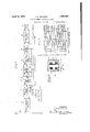
- FIG. 1- illustrates a radio receiver of the superheterodyne type in which the intermediate-frequency amplifier employs coupling'systems of the type of this invention
- Fig. 2 illustrates the construction of the indiameter of the shielding ring.
- Fig. shows transmission characteristic of the coupling system with and without the shield.
- Fig. 1 illustrates a conventional type of superheterodyne radio receiver embodying the invention.
- the receiver comprises an an- I tenna circuit connected to a radio-frequency amplifier shown in generalized form as the rectangle 11.
- the output of the radiofrequency amplifier is associated with a local oscillator indicated in generalized form by the rectangle 12.
- the local oscillator and the radio-frequency amplifier are connected in the input of a vacuum tube modulator 13, the purpose of the modulator being to modulate the amplified signals from the amplifier with the oscillations from the local oscillator.
- the construction of a local oscillator and of an amplifier for this purpose and the manner of their connection in the input circuit of the modulatorr are well understood in the art, and require no further discussion here.
- the modulator tube 13 is of the four-electrode type comprising an anode 14, a cathode 15, a control grid 16 and a screen grid 17.
- the modulator 13 operates in the well understood manner upon the signal voltage and the local oscillator voltage to produce a signal in its output having a carrier :frequency which is the difference between the frequency of the radio signal and the frequency of the local oscillator. Since this difference in frequency is lower than the frequencies of the radio signaling range', it is called an intermediate frequecy.
- the output ofthe modulator is coupled to the input of an intermediate-frequency amplifier 18 through a coupling system '19.
- the amplifier 18 is also of the four-electrode type and includes an anode 20, a cathode 21, a control grid 22 and a screen grid 23.
- the output of the intermediate-frequency amplifier is coupled to a detector tube 24 through a coupling system 25.
- the detector tube,- which is also of the four-electrode type, includes yan anode 26, a: cathode 27, a control grid 28 and a screen grid 29.
- the output of the detector feeds into an audio-frequency amplifier represented by the rectangle 30.
- the output of the audio amplifier operates a loudspeaker 31.
- the feature of this invention resides in the coupling systems 19 and 25 associated with the intermediate-frequency amplifier.
- the coupling system 19 comprises two circuits, the first of which is connected in the output of modulator 13 and the second of which is connected in the-input of amplifier 18.
- the first circuit includes an inductance 32 shunted by'a fixedV capacity 33, connected in the anode circuit of modulator 13.
- the second circuit includes an inductance 34 shunted by a fixed capacity 35, connected in the inputcircuit of amplifier 18.
- the inductances 32 and 34 are so arranged that thcreexists a substantial degree of magnetic coupling between them.
- the elements of the coupling system are so selected that each of the coupledcircuits is tuned to the frequency to be transmitted by the amplifier.
- There is provided a metallic shield 36 which enclosesV the inductances 32 and 34; the shield is physically situated with respect to the inductances, in accordance. with this invention, in a manner which will be later explained in greater detail. j;
- the coupling system 25 ⁇ in the output of the intermediate-frequency amplifier 18 is similar in its circuit arrangement to coupling system 19; it includes inductively related 4 inductances 37 and 38 situated respectively in the output circuit of the amplifier 18 and in the input circuit of the detector 24.
- the inductance 37 is shunted by a fixed condenser 39, and inductance 38 is shunted by fixed condenser 40.
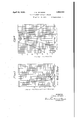
- Fig. 2 illustrates in cross-section the construction and assembly of the inductively related inductances and the associated shielding ring, of coupling systems 19 and 25.
- the arrangement comprises coils 41 and 42 random wound, or layer wound, respectively on bobbins 43 and 44.
- the bobbins are fastened over a core 45 which is adapted to be fastened to a base, or chassis, by brackets 46 and 47.
- Coil 41 is the anode circuit coil
- coil 42 is the grid circuit Scoil.
- the coil terminals marked A, B, C and D represent respectively the connections to the anode, the B-battery, the cathode and the grid of the associated tubes.
- a cylindrically-shaped shielding ring 48 Surrounding the bobbins containing the coils is a cylindrically-shaped shielding ring 48 closed at the upper end and adapted to be fastened to the base at the other end.
- the shielding ring is preferably heavy copper or aluminum or other metal A y coils-produces a magnetic field which interbetween the two coils.
- the current induced in the shield in turn, produces a magnetic field which is approximately opposite in phase to the ield of the first coil.
- the degree of coupling between the two coils is reduced to a lower value than would exist in the absence of the shield.o
- the dimensions of the coils will, of course, be dependent upon the intermediate frequency which the amplifier is required to transmit.
- the following table gives a suitable design for a coupling system for transmitting a carrier frequency of 417 5 kilocycles per seconda, and the associated sidebands, this frequency having been found highly satisfactory for the intermediate frequency of a superheterodyne receiver Diameter of core /g 1 Each wnding 900 turns. #'38 B & S
- Curve c indicates the variation in the eifective coeiiicient of coupling when the inside diameter of the shielding ring is two times the outside coil diameter. A casual inspection of the curves of Fig. 3 shows that the effective coupling between the coils becomes smaller when the distance between coils becomes greater relative to the outside coil diameter.
- Fig. 4 illustrates another family of curves which may be derived from the curves of Fig. Vl'n 3 and which showthe effect of the diameter of the shielding ring upon the effective electromagnetic coupling between the coils.
- the effective coetlicient of coupling is plotted against the ratio ofthe inside diam- 'f eter of the shielding ring to'the outside coil diameter.
- Curve a shows thevariation of the effective coefficient of coupling between the coils when the distance between the coil centers is one-half the outside coil diameter.
- Curve b illustrates the variation in the effective coefficient of coupling when the distance between the coil centers is three quartersof the outside coil diameter.
- Curve c indicates the variation when the distance between coil centers is equal to the outside coil diameter.
- the curves ofAFigs. 3 and 4 are experimental curves obtained from the coil structures' having ⁇ the design constants given in the above table. Experimentswith coil and shielding ring structures of various sizes and shapes have indicated that the most important variables are the ratio of the inside diameter of the shielding ring to the outside coil diameter, andthe ratio of the coil separation to the outside coil diameter.
- the most favorable ratios of the inside shielding ring ⁇ diameter to the outside coil diameter lie between one and two. .
- the spacing required between coils is subject to variation, dependent upon the desired coetiicient of coupling and hence the mutual inductance required", the power factor of the coils. the f form. factor of the coils. and the -diameter of. the shielding ring. llVhen 'the coil structure is proportioned in accordance with the above table. favorable reresults are obtained when the spacing be: tween the centers of the coils does not exceed the mean diameter of either coil. There the radius of the core itself is equal to or greater than the depth of winding of the coil.
- the spacing between centers of therespective coils may be reduced to a distance which is of the same order of magnitude as one-half the mean diameter of the coil.
- Fig. 5 illustrates amplification characteristics of a coupling system such as 19 and Q5 of Fig. l.
- Curve aof Fig. 5 illustrates the amplification characteristic when the shielding ring is removed: the coupling coefficient Tint) l'it;
- optimum coupling is meant that degree 'of coupling between the input and output circuits of a coupling system which will provide the maximum amplification.; It is well known that when the coupling between a pair of syntonously tuned circuitsl of a coupling system is optimum, or less than optimum, the system is characterized by a single resonance;v When the coupling becomes greater than optimum, the resonances spread, giving rise to the double-resonance effect. The distance in the frequency scale between the two resonances is greater, the greater the degree of coupling; so it is possible to obtain any desired spacing by ad- 4justing the coupling by means of the shield.
- the design required moderately over-optimum coupling to be employed. so that the double-resonance effect is obtained to a slight degree, whereby there results a broadening of the transmissionV band of frequencies; other design conditions require that there -be a single resonance. It is within the contemplation of this invention to provide either type of resonance characteristic. It is clear that whether a double resonance effect or a single resonance effect is to be obtained, the required coefficient of coulin0r is uite critical. This critical value can l be readily obtained i'n accordance with this invention, by suitably proportioning the dimensions of the shielding ring in relation to the coil dimensions. f
- a plurality of double tuned systems may be coupled either inductively or capacitively in tandem between successive vacuum tubes.
- a high-frequency coupling system comprising an input circuit and an output circuit, each of said circuits including an inductance tuned by a capacity to a frequency which is the carrier frequency to be transmitted, said inductances being located ink close proximity to each other, and an electrical conducting shield closely surrounding said inductances whereby the effective coefficient of coupling between said coils is of a sufficiently small magnitude so that said system as a whole tunes to the same frequency to which each of said circuits is individually tuned.
- a coupling system according to claim l in ⁇ which the distance between the centers of said inductances does not exceed the diameters of said inductances.
- a high-frequenc coupling system for transmitting a signal between a pair of Vacuum tubes comprising an inductance in the output of the first of said tubes and an inductance in the input of the second of said tubes, a capacity shunted across each of said inductaiices of such value as to cause each of said inductances to be resonant at the same frequency, said inductances being located in close proximity to each other so that acting independently there would exist such a high degree of magnetic coupling therebetween as to produce a double resonance characteristic, and shielding means so situated in relation to said coils that the coupling which would exist between said coils inthe absence of said means is reduced to the proper effective value to provide a single resonance characteristic.
- a high-frequency coupling system comprising an input circuit and an output circuit, each of said circuits including an inductance element, said inductance elements being placed so close together that there is a strong magnetic field. therebetween when said inductances act alone, and means associated with said inductance elements for ⁇ producing a magnetic field which is weaker than, and which opposes, said strong magnetic field, whereby the resultant magnetic field.
- interlinking said inductances is relatively vveak as compared with said strong magnetic eld.
- a high-frequency coupling system according to claim itin which said means for ⁇ producing the weaker magnetic field is a conducting ring surrounding said coils.
- an electrical conducting shield closelyA surrounding said iuductanceis whereby the effective coefficient of coupling between saidcoils is of a suiiiciently 'small magmtude' -so that said system as a whole tunes to the same frequency to which each of sald circuits is'individuallytuned v except .
- an electrical conducting shield closely. surrounding sald inductances 'Whe'reby the leiective coefficient o f magnetic coupling between sald co1lsl1s of a ,'suHcient-lysmall magnitude so that said system as a whole tunes to the same frequency to 'Whichueach of said circuits is individually tuned.
- shielding means so situated in relation to said coils 'that the coupling which 'would 'Y exist between said coils in the absence of said means is reduced to the proper effective value to provide a single resonance characteristic except such a shielding means so-situated iu relation to said coils vthat the magnetic coupling which would exist vbetween said coils in the absence ,of said'means is reduced *to the proper effective value to provide a single resonance characteristic.
- a high-frequency .coupling system comprising an mput circuit and an output circuit, each of. sald circults including an inductance element, which lnductance elements are spaced to provide acoellicientA agnetic coupling substantially less than unity, said inductance elements being placed so close together that there 1s a. stro magnetic field :therebetween wh'cn said. indu otances ⁇ act alone, and means whic comprises a magnetic Shield assoclated with said inductanceeleme'nts for producing a .magnetic field which is weaker than, and which opposes, said. strong 'magnetic field,l whereby the resultant magnetic field interlinking saidinductances 1s relatively weak as comparedwith said strong magnetic field.
- a high-frequency coupling system comprising 'an inputcircuit and'anoutput Y circuit, each of said circuits includedin .an inductance element "except such-A'high-freguencycoup n system compris' an input circuit. and "an ,output c11'cuit, each of said circuits include an lnductance e ement,y which inductance elements ⁇ are spaced toA providea coefijcient of magnetic coupling substantially' less l 4 wasJanes,19:33.]
Landscapes
- Shielding Devices Or Components To Electric Or Magnetic Fields (AREA)
Description
April 19,1932. J. .JOHNSON l 1,855,054
HIGH FREQUENGYGOUPLNG SYSTEM Filed Feb. 13, 1931 2 sheets-sheet 1 vApril 19, 1932-l J. K. JOHNSON 1 1,855,054
HIGH FREQUENCY COUPLING SYSTEM Filed Feb. 15, 1951 2 sheets-smet 2 ATTORNEYS Patented Apr. A19, 1932 UNITED STATES PATENT OFFICE JOHN KELLY JOHNSON, O'HARTSDALE, NEW YORK, ASSIGNOR TO HAZELTINE COR- PORATION, A. CORPORATION F DELAWARE HIGH-.FREQUENCY COUPLING SYSTEM Application led February 13, 1931. Serial No. 515,560.
4This invention relates to carrier-frequency 'coupling systems and more particularly to systems adapted to couple vacuum tubes 1n an amplifier of high or medium-high fre- The coupling systems of the present invention are suitable for use in radio-frequency amplifiers and are particularly well adapted for use in amplifiers of medium-high fre- 1'0 quencies, such as the intermediate-frequency is connected to a pair of input terminals and an output circuit which is connected to a pair of output terminals. The input and output circuits each include an inductance tuned by a capacity; these inductance elements are coils which are spaced in close relation to each other so that there exists a substantial. degree of magnetic coupling p therebetween. The coupling system will generally be connected between thev ouput of one tube of al high-frequency amplifier and the input of a succeeding tube. There may be two or more ofthese coupling systems coupled in tandem.
An important feature of the -invention is the provision of an electrical conducting shielding arrangement surrounding, or partially surrounding, both coils. |This shielding arrangement has the effect of reducing the degree of coupling between the inductances of the input and output circuits to a lower value than would exist inthe absence of the shield. The amount by-which the effective Ycoupling between the coils is reduced by virtue of the shield, depends upon the form and` separation' of vthe coils and ondary windings each of which is tuned to the same frequency by fixed or adjustable capacities, it has been found necessary, where relatively loose coupling between circuits is required, to physically space the coils a considerabledistance apart, or in the alternative, to provide an auxiliary element between the windings to reduce the electromagnetic coupling. If this relatively great spacing between tbe coils is not provided,vor if there is present no auxiliary means for reducing the coupling, there results the well-known effect of double resonance which makes it impossible to tune the system to a single frequency.
The reaction of one circuit upon the other produces the two resonant peaks each of which differs from the frequency to which each coil is individually tuned. When the electromagnetic coupling between the two circuits is decreased, the frequency difference between these resonant peaks decreases, so as optimum coupling is approached, the double resonant peaks merge into the single resonance.
It has been found possible to vary the effective coeicient of electromagnetic coupling and hence the mutual inductance between the coils within wide limits by varying the relative sizes of the shielding ring and of the coils and the spacing between coils. By arranging the shielding ring close to the coils it is possible to locate the coils in close proximity to each other while at the same time maintaining absolute control over the effective coeiiicient of coupling and the mutual inductance between coils, and hence the reaction of one circuit upon the other. Practicall-y, it is possible to so arrange the elements of the coil structure that it is small, compact and inexpensive to manufacture.
Of the drawingsi v Fig. 1- illustrates a radio receiver of the superheterodyne type in which the intermediate-frequency amplifier employs coupling'systems of the type of this invention;
Fig. 2 illustrates the construction of the indiameter of the shielding ring.
Fig. shows transmission characteristic of the coupling system with and without the shield.
Fig. 1 illustrates a conventional type of superheterodyne radio receiver embodying the invention. The receiver comprises an an- I tenna circuit connected to a radio-frequency amplifier shown in generalized form as the rectangle 11. lThe output of the radiofrequency amplifier is associated with a local oscillator indicated in generalized form by the rectangle 12. The local oscillator and the radio-frequency amplifier are connected in the input of a vacuum tube modulator 13, the purpose of the modulator being to modulate the amplified signals from the amplifier with the oscillations from the local oscillator. The construction of a local oscillator and of an amplifier for this purpose and the manner of their connection in the input circuit of the modulatorr are well understood in the art, and require no further discussion here.
The modulator tube 13 is of the four-electrode type comprising an anode 14, a cathode 15, a control grid 16 and a screen grid 17. The modulator 13 operates in the well understood manner upon the signal voltage and the local oscillator voltage to produce a signal in its output having a carrier :frequency which is the difference between the frequency of the radio signal and the frequency of the local oscillator. Since this difference in frequency is lower than the frequencies of the radio signaling range', it is called an intermediate frequecy.
The output ofthe modulator is coupled to the input of an intermediate-frequency amplifier 18 through a coupling system '19. The amplifier 18 is also of the four-electrode type and includes an anode 20, a cathode 21, a control grid 22 and a screen grid 23. The output of the intermediate-frequency amplifier is coupled to a detector tube 24 through a coupling system 25. The detector tube,- which is also of the four-electrode type, includes yan anode 26, a: cathode 27, a control grid 28 and a screen grid 29. The output of the detector feeds into an audio-frequency amplifier represented by the rectangle 30. The output of the audio amplifier operates a loudspeaker 31.
There are illustrated no sources of operating potentials for the various electrodes of the vacuum tubes of the receiver.- The manner of applying these energizing potentials 1s well understood in the art and since it constitutes no part of the present invention, these sources are not illustrated.
The feature of this invention resides in the coupling systems 19 and 25 associated with the intermediate-frequency amplifier. The coupling system 19 comprises two circuits, the first of which is connected in the output of modulator 13 and the second of which is connected in the-input of amplifier 18. The first circuit includes an inductance 32 shunted by'a fixedV capacity 33, connected in the anode circuit of modulator 13. The second circuit includes an inductance 34 shunted by a fixed capacity 35, connected in the inputcircuit of amplifier 18. The inductances 32 and 34 are so arranged that thcreexists a substantial degree of magnetic coupling between them. The elements of the coupling system are so selected that each of the coupledcircuits is tuned to the frequency to be transmitted by the amplifier. There is provided a metallic shield 36 which enclosesV the inductances 32 and 34; the shield is physically situated with respect to the inductances, in accordance. with this invention, in a manner which will be later explained in greater detail. j;
The coupling system 25 `in the output of the intermediate-frequency amplifier 18 is similar in its circuit arrangement to coupling system 19; it includes inductively related 4 inductances 37 and 38 situated respectively in the output circuit of the amplifier 18 and in the input circuit of the detector 24. The inductance 37 is shunted by a fixed condenser 39, and inductance 38 is shunted by fixed condenser 40.
Fig. 2 illustrates in cross-section the construction and assembly of the inductively related inductances and the associated shielding ring, of coupling systems 19 and 25. The arrangement comprises coils 41 and 42 random wound, or layer wound, respectively on bobbins 43 and 44. The bobbins are fastened over a core 45 which is adapted to be fastened to a base, or chassis, by brackets 46 and 47. Coil 41 is the anode circuit coil and coil 42 is the grid circuit Scoil. The coil terminals marked A, B, C and D, represent respectively the connections to the anode, the B-battery, the cathode and the grid of the associated tubes. Surrounding the bobbins containing the coils is a cylindrically-shaped shielding ring 48 closed at the upper end and adapted to be fastened to the base at the other end. The shielding ring is preferably heavy copper or aluminum or other metal A y coils-produces a magnetic field which interbetween the two coils.
links with the turns of the secnd coil and withA the shield. Currents are thereby induced in the second coil and in the shield.-
The current induced in the shield, in turn, produces a magnetic field which is approximately opposite in phase to the ield of the first coil. As a result, the degree of coupling between the two coils is reduced to a lower value than would exist in the absence of the shield.o
Due to the close spacing between the shieldving device and the coils and because of the low resistance of the shielding device, the
coefficient of coupling bet-Ween the coils and the shield will usually be greater than that It has been found possible, in fact, to reduce the effect-ive magnetic coupling between coils practically to zero.`
The dimensions of the coils will, of course, be dependent upon the intermediate frequency which the amplifier is required to transmit. The following table gives a suitable design for a coupling system for transmitting a carrier frequency of 417 5 kilocycles per seconda, and the associated sidebands, this frequency having been found highly satisfactory for the intermediate frequency of a superheterodyne receiver Diameter of core /g 1 Each wnding 900 turns. #'38 B & S
. l gauge, double silk covered copper wire. Width of each coil Distance between coils 17s" Outside diameter of each coil t?" Inside diameter of shielding ring". 3ft" Length of shielding ring 1%" The above dimensions will provide a 'coil structure having an inductance of about 8.8 millihenries in each coil; the effective coefficient of coupling between each coil will be about four per cent. In order to causeeach `of the coils to be resonant at a .frequency of shielding ring' which is so proportioned that the inside diameter of the ring is one and one-third times the outside. coil diameter. Curve c indicates the variation in the eifective coeiiicient of coupling when the inside diameter of the shielding ring is two times the outside coil diameter. A casual inspection of the curves of Fig. 3 shows that the effective coupling between the coils becomes smaller when the distance between coils becomes greater relative to the outside coil diameter.
Fig. 4 illustrates another family of curves which may be derived from the curves of Fig. Vl'n 3 and which showthe effect of the diameter of the shielding ring upon the effective electromagnetic coupling between the coils. In this figure the effective coetlicient of coupling is plotted against the ratio ofthe inside diam- 'f eter of the shielding ring to'the outside coil diameter. Curve a shows thevariation of the effective coefficient of coupling between the coils when the distance between the coil centers is one-half the outside coil diameter. Curve b illustrates the variation in the effective coefficient of coupling when the distance between the coil centers is three quartersof the outside coil diameter. Curve c indicates the variation when the distance between coil centers is equal to the outside coil diameter. A
The curves ofAFigs. 3 and 4 are experimental curves obtained from the coil structures' having` the design constants given in the above table. Experimentswith coil and shielding ring structures of various sizes and shapes have indicated that the most important variables are the ratio of the inside diameter of the shielding ring to the outside coil diameter, andthe ratio of the coil separation to the outside coil diameter.
The most favorable ratios of the inside shielding ring` diameter to the outside coil diameter lie between one and two. .The spacing required between coils is subject to variation, dependent upon the desired coetiicient of coupling and hence the mutual inductance required", the power factor of the coils. the f form. factor of the coils. and the -diameter of. the shielding ring. llVhen 'the coil structure is proportioned in accordance with the above table. favorable reresults are obtained when the spacing be: tween the centers of the coils does not exceed the mean diameter of either coil. There the radius of the core itself is equal to or greater than the depth of winding of the coil. the spacing between centers of therespective coils may be reduced to a distance which is of the same order of magnitude as one-half the mean diameter of the coil. It should be understood that the above'mentioned preferred proportions should not be Aconstrued to be limitations upon the invention, but are given to indicate how favorable results may be obtained.
Fig. 5 illustrates amplification characteristics of a coupling system such as 19 and Q5 of Fig. l. Curve aof Fig. 5 illustrates the amplification characteristic when the shielding ring is removed: the coupling coefficient Tint) l'it;
iai
rise to the double resonance effect. 4Curve 7) illustrates the resonance characteristic of the same coupling system when the shielding ring is in place. The effective coupling coefficient between coilsis reduced by the ring to about 40%. This is slightly below optimum and produces the single resonance effect.
By the term optimum coupling is meant that degree 'of coupling between the input and output circuits of a coupling system which will provide the maximum amplification.; It is well known that when the coupling between a pair of syntonously tuned circuitsl of a coupling system is optimum, or less than optimum, the system is characterized by a single resonance;v When the coupling becomes greater than optimum, the resonances spread, giving rise to the double-resonance effect. The distance in the frequency scale between the two resonances is greater, the greater the degree of coupling; so it is possible to obtain any desired spacing by ad- 4justing the coupling by means of the shield.
In some amplifiers the design required moderately over-optimum coupling to be employed. so that the double-resonance effect is obtained to a slight degree, whereby there results a broadening of the transmissionV band of frequencies; other design conditions require that there -be a single resonance. It is within the contemplation of this invention to provide either type of resonance characteristic. It is clear that whether a double resonance effect or a single resonance effect is to be obtained, the required coefficient of coulin0r is uite critical. This critical value can l be readily obtained i'n accordance with this invention, by suitably proportioning the dimensions of the shielding ring in relation to the coil dimensions. f
Although there is illustrated in 'Fig 1 only onev double tuned coupling system between each successive tube, there are instances where it-is desirable to provide more than one such double tuned system between stages. A plurality of double tuned systems may be coupled either inductively or capacitively in tandem between successive vacuum tubes.
Although the coupling systems have been described Aas being particularly well suited for use in the intermediate frequency amplifiers of superheterodyne receivers, the invention should not be construed to be limited to such receivers. The coupling systems of this invention are equally applicable to radiofrequency amplifiers and to any other highfrequency system.
What is claimed is:
1. A high-frequency coupling system comprising an input circuit and an output circuit, each of said circuits including an inductance tuned by a capacity to a frequency which is the carrier frequency to be transmitted, said inductances being located ink close proximity to each other, and an electrical conducting shield closely surrounding said inductances whereby the effective coefficient of coupling between said coils is of a sufficiently small magnitude so that said system as a whole tunes to the same frequency to which each of said circuits is individually tuned.
2. A coupling system according to claim l in `which the distance between the centers of said inductances does not exceed the diameters of said inductances.
3. A high-frequenc coupling system for transmitting a signal between a pair of Vacuum tubes, comprising an inductance in the output of the first of said tubes and an inductance in the input of the second of said tubes, a capacity shunted across each of said inductaiices of such value as to cause each of said inductances to be resonant at the same frequency, said inductances being located in close proximity to each other so that acting independently there would exist such a high degree of magnetic coupling therebetween as to produce a double resonance characteristic, and shielding means so situated in relation to said coils that the coupling which would exist between said coils inthe absence of said means is reduced to the proper effective value to provide a single resonance characteristic.
' 4. A high-frequency coupling system comprising an input circuit and an output circuit, each of said circuits including an inductance element, said inductance elements being placed so close together that there is a strong magnetic field. therebetween when said inductances act alone, and means associated with said inductance elements for` producing a magnetic field which is weaker than, and which opposes, said strong magnetic field, whereby the resultant magnetic field.
interlinking said inductances is relatively vveak as compared with said strong magnetic eld.
5. A high-frequency coupling system according to claim itin which said means for `producing the weaker magnetic field is a conducting ring surrounding said coils.
Intestimony whereof I affix my signature.
J. KELLY JOHNSON.
DISC-LAIMER v 1,855,054l-John Kelly Johnson, Hartsdale, N. HIGH-FREQUENCY kCotIPLING SYSTEM. Patent dated April 19, 1932. Disclaimer led February 23, 1933? by the patentee, assignee, Hazeltne Corporation, consenting.
Tlerefore, enters this disclaimer to claims 1 and 3 of said Letters Patent, tozwit: A
He disclaims from claim l:
"an electrical conducting shield closelyA surrounding said iuductanceis whereby the effective coefficient of coupling between saidcoils is of a suiiiciently 'small magmtude' -so that said system as a whole tunes to the same frequency to which each of sald circuits is'individuallytuned v except .such an electrical conducting shield closely. surrounding sald inductances 'Whe'reby the leiective coefficient o f magnetic coupling between sald co1lsl1s of a ,'suHcient-lysmall magnitude so that said system as a whole tunes to the same frequency to 'Whichueach of said circuits is individually tuned.
He disclaims from claim 3:
shielding means so situated in relation to said coils 'that the coupling which 'would 'Y exist between said coils in the absence of said means is reduced to the proper effective value to provide a single resonance characteristic except such a shielding means so-situated iu relation to said coils vthat the magnetic coupling which would exist vbetween said coils in the absence ,of said'means is reduced *to the proper effective value to provide a single resonance characteristic. [Oficial Gazette 'March 14, 1.933.]
DISCLAIMER A 1,855,054'.-John Kelly Johnson, Hartsdale, N. Y. HIGH-FREQUENCY CoUPmNG l SYSTEM. Patent dated April 19, 1932. Disclaimer filed February 23, 1933 by the patentee, assignee, Hazeltfine Corporation, oonsemn'ng.`
Therefore, enters this disclaimer to claims 1 and 3 of saidl Letters Patent, tolwit: l
H e disclaims from claim 1:
an electrical conducting shield closelyA surrounding said iriductancejs whereby the Q effective coeicient of coupling between saidcoils is of a sufciently small magnitude' circuits is-individually tuned1 except such an electrical conducting shield closely surrounding said inductances 'Whe'reby the effective coecient of magnetic coupling between said coils is of a suficiently'small magnitude so that said system as a who e tunes to the same frequency to whicheach o'f said circuits is individually tuned.
He disclaims, from claim 3:
so that said system as a whole tunes to the same frequency to which each of said shielding means so situated in relation to said coils .that the coupling which would exist between said coils 'in the absence of said means is reduced to the proper effective value to provide a single resonance characteristic except such a shielding means sosituated in relationtc said coils that the magnetic to the proper effective value to provide a single resonance characteristic.
coupling which would exist between said coils in the absence .of said means is redu Oficial Gazette Mami 1.4, 1933.1
1,855,054'.John Kelly Johnson, Hartsdale, N Y. HIGH-FQUENCYCOUPLING'.
SYSTEM. Patent dated April- 19, 19321. Disclaimer'filed 'November 12, 1934, by thc assignee, Hdzeltine Corporation. Therefore, enters this disclaimer to'claims 4 and 5 .of lsaidflael'ftere Patent, which, subject to the disclalmer filedl May 6, 1933, are in the following words, to wit:
4. A high-frequency .coupling system comprising an mput circuit and an output circuit, each of. sald circults including an inductance element, which lnductance elements are spaced to provide acoellicientA agnetic coupling substantially less than unity, said inductance elements being placed so close together that there 1s a. stro magnetic field :therebetween wh'cn said. indu otances`act alone, and means whic comprises a magnetic Shield assoclated with said inductanceeleme'nts for producing a .magnetic field which is weaker than, and which opposes, said. strong 'magnetic field,l whereby the resultant magnetic field interlinking saidinductances 1s relatively weak as comparedwith said strong magnetic field.'
f 5. lugh-frequencyc'oupling systemaccordingr to claim 4 in which said means for producing the weaker magnetlc fic d 1s a conducting ring surrounding said coils.` [Oficial Gazette December 4, 1.934.]
, CERTIFICATI: or CORRECTION. y Patent No., 1,855;054. l l (ranted April 1.9,j to
` V JoHN KELLY JoHNsoN, I
It is hereby certified that errorjappears in the printed .speeif'icat'i'on of the above numbered patent requiringcorrection as follows: Page 4, line 6,'. fot
"40%'"read 4%; and that the said` Letters Patent should be read with this'eorrection therein that the same m'dy conform to the record of the case in the Patent'Office. f s .v
Signed andsealed this 31st day of May, A. D."l932.
Mc Ji -(Seal) Acting ,Comnijseioner of Patenti.
DISQLI'Mr-: l 1,855,054.-"Jolm Kelly Johnson, Hartsdale', N.Y. HIGH FREQUENcr fCoUPLrNG SYSTEM. Patent dated Ap\ri1,19, 19321 ,Disclaimer led May 6", i933, by the patentee, assignee, Hazeltine Corporation, consenting. Therefore enters this disclaimer t9 claims 4` and 5 of said Letters P at'entfltoi wit: He disclaims from claim 4:
means associated withA said inductance. eiements for producing a `etic y'field which is weaker than, and'which opposes, sald strong magnetic field J except such-means which compr1ses a magnetic shield assoclated induc' tance elements for producing a magnetic ield'which is weaker than, 'and which' op oses, said strong magnetic e1de disclaimsfrom claims 4 and 5:
A high-frequency coupling system comprising 'an inputcircuit and'anoutput Y circuit, each of said circuits includin .an inductance element "except such-A'high-freguencycoup n system compris' an input circuit. and "an ,output c11'cuit, each of said circuits inclu an lnductance e ement,y which inductance elements` are spaced toA providea coefijcient of magnetic coupling substantially' less l 4 wasJanes,19:33.]
Priority Applications (2)
| Application Number | Priority Date | Filing Date | Title |
|---|---|---|---|
| US515560A US1855054A (en) | 1931-02-13 | 1931-02-13 | High-frequency coupling system |
| US518996A US1855055A (en) | 1931-02-13 | 1931-02-28 | High frequency transformer |
Applications Claiming Priority (1)
| Application Number | Priority Date | Filing Date | Title |
|---|---|---|---|
| US515560A US1855054A (en) | 1931-02-13 | 1931-02-13 | High-frequency coupling system |
Publications (1)
| Publication Number | Publication Date |
|---|---|
| US1855054A true US1855054A (en) | 1932-04-19 |
Family
ID=24051839
Family Applications (1)
| Application Number | Title | Priority Date | Filing Date |
|---|---|---|---|
| US515560A Expired - Lifetime US1855054A (en) | 1931-02-13 | 1931-02-13 | High-frequency coupling system |
Country Status (1)
| Country | Link |
|---|---|
| US (1) | US1855054A (en) |
Cited By (5)
| Publication number | Priority date | Publication date | Assignee | Title |
|---|---|---|---|---|
| US2501488A (en) * | 1946-07-19 | 1950-03-21 | Zenith Radio Corp | Magnetostrictively driven mechanical wave filter |
| US3362002A (en) * | 1965-12-01 | 1968-01-02 | Tesla Np | Inductive measuring device having a conductive shield |
| US5361306A (en) * | 1993-02-23 | 1994-11-01 | True Dimensional Sound, Inc. | Apparatus and methods for enhancing an electronic audio signal |
| US6275593B1 (en) | 1996-05-10 | 2001-08-14 | True Dimensional Sound, Inc. | Apparatus and methods for the harmonic enhancement of electronic audio signals |
| US20050259833A1 (en) * | 1993-02-23 | 2005-11-24 | Scarpino Frank A | Frequency responses, apparatus and methods for the harmonic enhancement of audio signals |
-
1931
- 1931-02-13 US US515560A patent/US1855054A/en not_active Expired - Lifetime
Cited By (5)
| Publication number | Priority date | Publication date | Assignee | Title |
|---|---|---|---|---|
| US2501488A (en) * | 1946-07-19 | 1950-03-21 | Zenith Radio Corp | Magnetostrictively driven mechanical wave filter |
| US3362002A (en) * | 1965-12-01 | 1968-01-02 | Tesla Np | Inductive measuring device having a conductive shield |
| US5361306A (en) * | 1993-02-23 | 1994-11-01 | True Dimensional Sound, Inc. | Apparatus and methods for enhancing an electronic audio signal |
| US20050259833A1 (en) * | 1993-02-23 | 2005-11-24 | Scarpino Frank A | Frequency responses, apparatus and methods for the harmonic enhancement of audio signals |
| US6275593B1 (en) | 1996-05-10 | 2001-08-14 | True Dimensional Sound, Inc. | Apparatus and methods for the harmonic enhancement of electronic audio signals |
Similar Documents
| Publication | Publication Date | Title |
|---|---|---|
| US2140770A (en) | Electrical coupling device | |
| US2325279A (en) | Signal collecting system | |
| US1855054A (en) | High-frequency coupling system | |
| US2131976A (en) | Image suppression system | |
| US2383475A (en) | Transformer | |
| US2359684A (en) | Loop input system for radio receivers | |
| US2285957A (en) | Balanced frequency detector | |
| US2075683A (en) | Image frequency rejection system | |
| US1690228A (en) | High-frequency transformer | |
| US3576495A (en) | Tuning circuit having means for compensating for the coupling of the local oscillator signal to the antenna winding | |
| US2270017A (en) | Tuned circuits | |
| US2144029A (en) | High frequency coupling device | |
| US2125119A (en) | Coupling transformer | |
| US1855055A (en) | High frequency transformer | |
| US1933402A (en) | Double band receiver | |
| US2517741A (en) | Permeability-tuned variable-frequency amplifier | |
| US2334670A (en) | Radio amplifying circuit | |
| US2083901A (en) | Selective coupling circuits | |
| US2470882A (en) | Receiver input circuit | |
| US2281488A (en) | Radio receiver | |
| US2402260A (en) | Permeability tuned short-wave spread-band receiver | |
| US2550486A (en) | Wave-signal transformer | |
| US2457774A (en) | Inductively coupled band-pass filter | |
| US1954470A (en) | High frequency transformer | |
| US2242330A (en) | Interference suppression system |