US1855030A - Airplane swing - Google Patents
Airplane swing Download PDFInfo
- Publication number
- US1855030A US1855030A US479364A US47936430A US1855030A US 1855030 A US1855030 A US 1855030A US 479364 A US479364 A US 479364A US 47936430 A US47936430 A US 47936430A US 1855030 A US1855030 A US 1855030A
- Authority
- US
- United States
- Prior art keywords
- swing
- airplane
- shives
- lever
- ropes
- Prior art date
- Legal status (The legal status is an assumption and is not a legal conclusion. Google has not performed a legal analysis and makes no representation as to the accuracy of the status listed.)
- Expired - Lifetime
Links
- 230000006978 adaptation Effects 0.000 description 1
- 238000010276 construction Methods 0.000 description 1
- 239000011435 rock Substances 0.000 description 1
Images
Classifications
-
- A—HUMAN NECESSITIES
- A63—SPORTS; GAMES; AMUSEMENTS
- A63G—MERRY-GO-ROUNDS; SWINGS; ROCKING-HORSES; CHUTES; SWITCHBACKS; SIMILAR DEVICES FOR PUBLIC AMUSEMENT
- A63G9/00—Swings
- A63G9/10—Swings with seats shaped as riding horses, breeches, or the like
Definitions
- My invention relates to airplane swings and certain objects of the invention'a-re to provide a swing designed to represent an airplane and having forward and rear ropes passed through holes in the body of the swing with shive supports therefor disposed 1n cooperative relation with seats, a rear platform and depending foot rests whereby the swing may be rocked sideways by its occupants in addition to its regular forward and backward movements. Further objects are to provide a novel lever arrangement whereby the weight of the device may be shifted from direct bearing of the ropes on the swing body to a bearing on the shives, an d also to provide locking means for the lever system and adjustable means for the foot rests.
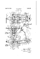
- Fig. 2 is a view in transverse vertical section taken on a broken line 2,'2 of Fig. 3;
- Fig. 3 is a view in side elevation of the swing.
- Fig. 4 is a detail view in perspective showing one of the shift roller devices.
- the numeral 5 designates the body of the swing that is shaped to represent the gondola or body of an airplane. Said body is provided with a toy propeller 6, seats 8 and 9, and a rear platformV 10.
- Foot rests are provided for occupants of the seats 8 and 9 comprising a pair lof oppositely disposed side supports 11 secured below each seat to the sides of the swing body 5 and extending downwardly and outwardly from the body.
- Said side supports are all provided on their rear edges with a series of notches 12 that are adapted to receive a rod 13 for each pair of supports extending transversely of the plane" body.
- Said rods may be adjustably shifted up or down in the. notches to serveas foot restsforl children of dierentl ages or sizes as wil-l beunderstood.
- the swing body 5 is supported by a forward ropeV 14 anda rear ropey 15.
- the two ends of both ropes may be fastened in spacedapart relation to, rings 16 or the like which may be securedj to anydesired overhead stationary,
- The' loop of the forward rope passes through a h'olel' in the forwardportion of the swingbodywhile the loop-of the rear rope passes through a hole 18 in the rear or tailportion of the' body.y
- the frictional engagement of said ropes with the body and within the holes serves to retain the swing body normally in a level. position and ⁇ preventits tipping from sideto side.
- Shives,v such as' shown at 19,y may be provided for 'the wing 7 and rear platform 10 in order to prevent wear of theropes at these points.
- a rectangular foot leverl 20 is pivoted to the under forwardv side ofl the body.
- a rod 21 extends to the lowerend of a control -lever 22 pivoted at 23 on ⁇ each! side l of the swing body belowv the seat 8.
- another rod 24 extends rearward to the arms 25 of aV bracket shive support orbearing 26 on each side and from the tops of said leversa rod 27 extends forward to the arms. 28 of corresponding bracket shive ⁇ supportsor bearings 29 on either side. 4
- the arms 25 of the ⁇ bracket'supports 26 are pivoted at 30 ⁇ to either side ofthe tail portionof the body 5 in such manner that their shives 31 may'engage-the rear rope 15,
- Vwhilethe arms28-of the bracket su-pport29 are pivoted at 32 to the "swing body sides whereby their shivesl 33 may engage the for# ward ropei14.
- a pin 34 may be passed through a hole in said levers and into any one of a series of holes 35 inthe sidesof the swing body as clearly shown in Fig. 3 of said shives into and out of supporting en-v the drawings.
- This lever rod arrangement provides means whereby the Y weight of the device may be lifted or transferred to the shives 3l and 33.
- the lever 22 By pressing forward on thefoot lever 20 the lever 22 will cause the bracket shive supports 26 and 29 to pivotally move whereby their shives 31 and 33 -are simultaneously forcedY l downwardA against theiropes 15 and 14 re'-l spectively to take up the support Vof the swing Vbody as will be understood.
- the swing By holding said levers in this position with the feet orl by locking same'with the pins 34 the swing mayY -l be readily rocked from side to side inan ⁇ amusing way to simulate the movements of an airplane.
- theshives provides means whereby a child standing onthe rear platform 10as shownin Vdotted lines in Fig. 3, or seated in one of the seats 8 or 9 may readily cause the swingbody to'rock from side to side invaddition to itsregular forwardand backward swing movement.
- An airplane swing having in combina-k tionl a swing body shapedA in the form of an airplane,'seats upon the mid portion of the body, a'platformV upon 'the rear lend portion of thebody, fot rests disposed below the body adjacent the seats, adjusting means for raising and lowering the footrests, a forward rope passed loosely through a hole in the forward end portion of the body, a rear rope passed loosely through a holel in the rear Y end portion of the body, the ends of said ropes connectedV to a single overhead support, shives pivotally'mounted upon said body ad acent each of said holes, and means for moving /said shives into and out of supporting 'engagement with ropes.
- An airplane swing having in combination a swing body shaped in the form of an airplane, seats uponI the mid portion of the body,l a platform upon the rearend portion of the body, foot rests disposed below the body adjacent 'theseats, adjusting means forv raising and lowering the foot rests, a forward' ropepassed loosely through aphole inthe forward end portion of the body, a rear rope passed loosely through a hole in the rear end portion of the body, the ends lof said ropes secured to a single overhead support, shives pivotallymounted upon said body adjacent each of said holes, lever means for moving
Landscapes
- Carriages For Children, Sleds, And Other Hand-Operated Vehicles (AREA)
Description
April 19, 1932. A. E. SCHANG 1,855,030 AIRPLANE SWING Filed Sept. 2, 1930 INVENTOR.
ATTORNEY.
. yarruinar 11. sonANG, or PE ELL, WASHINGTON, AssrGN'Oit on ONE-HALF' JOHNSON, or SEATTLE, WASHINGTON Patented Apr. 19, 1932 UNITED STATES PATENT OFFICE- AIRPLANE i SWING Applica/:mined september 2,1930. serial N0.f479,3e4.`
My invention relates to airplane swings and certain objects of the invention'a-re to provide a swing designed to represent an airplane and having forward and rear ropes passed through holes in the body of the swing with shive supports therefor disposed 1n cooperative relation with seats, a rear platform and depending foot rests whereby the swing may be rocked sideways by its occupants in addition to its regular forward and backward movements. Further objects are to provide a novel lever arrangement whereby the weight of the device may be shifted from direct bearing of the ropes on the swing body to a bearing on the shives, an d also to provide locking means for the lever system and adjustable means for the foot rests.
With the above and other objects in view which will appear as the description proceeds, the invention consists of the novel construction, adaptation, combination and arrangement of parts hereinafter described and claimed. These objects are accomplished by devices illustrated in the accompanying draw ings wherein Figure 1 is a top plan view of an airplane swing embodying the features of the invention;
Fig. 2 is a view in transverse vertical section taken on a broken line 2,'2 of Fig. 3;
Fig. 3 is a view in side elevation of the swing; and
Fig. 4 is a detail view in perspective showing one of the shift roller devices.
Referring to the drawings throughout which like reference numerals indicate like parts, the numeral 5 designates the body of the swing that is shaped to represent the gondola or body of an airplane. Said body is provided with a toy propeller 6, seats 8 and 9, and a rear platformV 10.
Foot rests are provided for occupants of the seats 8 and 9 comprising a pair lof oppositely disposed side supports 11 secured below each seat to the sides of the swing body 5 and extending downwardly and outwardly from the body. Said side supports are all provided on their rear edges with a series of notches 12 that are adapted to receive a rod 13 for each pair of supports extending transversely of the plane" body. Said rods may be adjustably shifted up or down in the. notches to serveas foot restsforl children of dierentl ages or sizes as wil-l beunderstood.
The swing body 5 is supported by a forward ropeV 14 anda rear ropey 15. The two ends of both ropesmay be fastened in spacedapart relation to, rings 16 or the like which may be securedj to anydesired overhead stationary,
object. The' loop of the forward rope passes through a h'olel' in the forwardportion of the swingbodywhile the loop-of the rear rope passes through a hole 18 in the rear or tailportion of the' body.y Ordinarily the frictional engagement of said ropes with the body and within the holes serves to retain the swing body normally in a level. position and` preventits tipping from sideto side. Shives,v such as' shown at 19,y may be provided for 'the wing 7 and rear platform 10 in order to prevent wear of theropes at these points.
In order to provide means :for eliminating the friction between the ropes 14 and 15 within `the holes 17 and18j respectively so that the swing body 5 may be rocked `froml side to'side, a rectangular foot leverl 20 is pivoted to the under forwardv side ofl the body. "From each side memberofsaid lever a rod 21 extends to the lowerend of a control -lever 22 pivoted at 23 on `each! side l of the swing body belowv the seat 8. From the lower end `ofA said control levers another rod 24 extends rearward to the arms 25 of aV bracket shive support orbearing 26 on each side and from the tops of said leversa rod 27 extends forward to the arms. 28 of corresponding bracket shive` supportsor bearings 29 on either side. 4
The arms 25 of the` bracket'supports 26 are pivoted at 30`to either side ofthe tail portionof the body 5 in such manner that their shives 31 may'engage-the rear rope 15,
Vwhilethe arms28-of the bracket su-pport29 are pivoted at 32 to the "swing body sides whereby their shivesl 33 may engage the for# ward ropei14. In order to provide means whereby the control levers 22 may be locked in any desired position, a pin 34 may be passed through a hole in said levers and into any one of a series of holes 35 inthe sidesof the swing body as clearly shown in Fig. 3 of said shives into and out of supporting en-v the drawings. n
This lever rod arrangement provides means whereby the Y weight of the device may be lifted or transferred to the shives 3l and 33. By pressing forward on thefoot lever 20 the lever 22 will cause the bracket shive supports 26 and 29 to pivotally move whereby their shives 31 and 33 -are simultaneously forcedY l downwardA against theiropes 15 and 14 re'-l spectively to take up the support Vof the swing Vbody as will be understood. By holding said levers in this position with the feet orl by locking same'with the pins 34 the swing mayY -l be readily rocked from side to side inan` amusing way to simulate the movements of an airplane. f
The cooperative relation l'of the rear platform 10itogetherwith the disposition of the foot rest rods'f13. below the swing vbody and.
with respect to the points of support of the body -by theshives provides means whereby a child standing onthe rear platform 10as shownin Vdotted lines in Fig. 3, or seated in one of the seats 8 or 9 may readily cause the swingbody to'rock from side to side invaddition to itsregular forwardand backward swing movement. v
Having thus described my invention, it beingvunderstood that minor changes in its constructiony and larrangementmay be resorted `to without departing from the scope and'spirit of the invention, I,what I claim and desire to secure by Letters Patent of the United St'atesis:v
1. An airplane swing having in combina-k tionl a swing body shapedA in the form of an airplane,'seats upon the mid portion of the body, a'platformV upon 'the rear lend portion of thebody, fot rests disposed below the body adjacent the seats, adjusting means for raising and lowering the footrests, a forward rope passed loosely through a hole in the forward end portion of the body, a rear rope passed loosely through a holel in the rear Y end portion of the body, the ends of said ropes connectedV to a single overhead support, shives pivotally'mounted upon said body ad acent each of said holes, and means for moving /said shives into and out of supporting 'engagement with ropes.
2. An airplane swing having in combination a swing body shaped in the form of an airplane, seats uponI the mid portion of the body,l a platform upon the rearend portion of the body, foot rests disposed below the body adjacent 'theseats, adjusting means forv raising and lowering the foot rests, a forward' ropepassed loosely through aphole inthe forward end portion of the body, a rear rope passed loosely through a hole in the rear end portion of the body, the ends lof said ropes secured to a single overhead support, shives pivotallymounted upon said body adjacent each of said holes, lever means for moving
Priority Applications (1)
| Application Number | Priority Date | Filing Date | Title |
|---|---|---|---|
| US479364A US1855030A (en) | 1930-09-02 | 1930-09-02 | Airplane swing |
Applications Claiming Priority (1)
| Application Number | Priority Date | Filing Date | Title |
|---|---|---|---|
| US479364A US1855030A (en) | 1930-09-02 | 1930-09-02 | Airplane swing |
Publications (1)
| Publication Number | Publication Date |
|---|---|
| US1855030A true US1855030A (en) | 1932-04-19 |
Family
ID=23903694
Family Applications (1)
| Application Number | Title | Priority Date | Filing Date |
|---|---|---|---|
| US479364A Expired - Lifetime US1855030A (en) | 1930-09-02 | 1930-09-02 | Airplane swing |
Country Status (1)
| Country | Link |
|---|---|
| US (1) | US1855030A (en) |
Cited By (1)
| Publication number | Priority date | Publication date | Assignee | Title |
|---|---|---|---|---|
| US2524967A (en) * | 1946-09-05 | 1950-10-10 | Sherman C Moore | Portable push-pull swing |
-
1930
- 1930-09-02 US US479364A patent/US1855030A/en not_active Expired - Lifetime
Cited By (1)
| Publication number | Priority date | Publication date | Assignee | Title |
|---|---|---|---|---|
| US2524967A (en) * | 1946-09-05 | 1950-10-10 | Sherman C Moore | Portable push-pull swing |
Similar Documents
| Publication | Publication Date | Title |
|---|---|---|
| US3033585A (en) | Vehicles | |
| US555049A (en) | Pleasure-railway | |
| US2743104A (en) | Spring mounted rocking horse | |
| US1855030A (en) | Airplane swing | |
| US2655116A (en) | Tilting track amusement apparatus | |
| US1529467A (en) | Gymnastic apparatus for children | |
| US2506890A (en) | Amusement or exercising device | |
| US3447802A (en) | Flight simulating swing | |
| US2358098A (en) | Swing | |
| US1737032A (en) | Amusement ride | |
| US2525377A (en) | Toy horse swing | |
| US1632405A (en) | Vehicle | |
| US1412723A (en) | Child's rocker | |
| US1548617A (en) | Rocking-chair or amusement device for children | |
| US1592419A (en) | Coaster sled | |
| US2627895A (en) | Rolling armchair | |
| US1646160A (en) | Swing | |
| US1659735A (en) | Combined merry-go-round and seesaw | |
| US3076666A (en) | Hoop-shaped vehicle having occupant seat therein | |
| US3618940A (en) | Simulated airplane seesaw supported on dissimilar rockers | |
| US2239982A (en) | Toy | |
| US1603052A (en) | Swing | |
| US1648745A (en) | Combined toy and exerciser | |
| US1684250A (en) | Rocking-horse toy | |
| US2052915A (en) | Swing |