US1854986A - Method and means for producing high frequencies - Google Patents
Method and means for producing high frequencies Download PDFInfo
- Publication number
- US1854986A US1854986A US453394A US45339430A US1854986A US 1854986 A US1854986 A US 1854986A US 453394 A US453394 A US 453394A US 45339430 A US45339430 A US 45339430A US 1854986 A US1854986 A US 1854986A
- Authority
- US
- United States
- Prior art keywords
- frequency
- frequencies
- oscillations
- side band
- harmonics
- Prior art date
- Legal status (The legal status is an assumption and is not a legal conclusion. Google has not performed a legal analysis and makes no representation as to the accuracy of the status listed.)
- Expired - Lifetime
Links
- 238000000034 method Methods 0.000 title description 8
- 230000010355 oscillation Effects 0.000 description 21
- 238000001228 spectrum Methods 0.000 description 4
- 238000010276 construction Methods 0.000 description 3
- 239000004020 conductor Substances 0.000 description 2
- 238000001914 filtration Methods 0.000 description 2
- 238000012986 modification Methods 0.000 description 2
- 230000004048 modification Effects 0.000 description 2
- 241000718541 Tetragastris balsamifera Species 0.000 description 1
- 230000008878 coupling Effects 0.000 description 1
- 238000010168 coupling process Methods 0.000 description 1
- 238000005859 coupling reaction Methods 0.000 description 1
- 238000010586 diagram Methods 0.000 description 1
- 230000007717 exclusion Effects 0.000 description 1
- 238000004804 winding Methods 0.000 description 1
Images
Classifications
-
- H—ELECTRICITY
- H03—ELECTRONIC CIRCUITRY
- H03B—GENERATION OF OSCILLATIONS, DIRECTLY OR BY FREQUENCY-CHANGING, BY CIRCUITS EMPLOYING ACTIVE ELEMENTS WHICH OPERATE IN A NON-SWITCHING MANNER; GENERATION OF NOISE BY SUCH CIRCUITS
- H03B21/00—Generation of oscillations by combining unmodulated signals of different frequencies
- H03B21/01—Generation of oscillations by combining unmodulated signals of different frequencies by beating unmodulated signals of different frequencies
- H03B21/02—Generation of oscillations by combining unmodulated signals of different frequencies by beating unmodulated signals of different frequencies by plural beating, i.e. for frequency synthesis ; Beating in combination with multiplication or division of frequency
Definitions
- My invention relates to a method and means l for producing'a plurality Yofhigh frequencies which are spaced apart in the frequency spectrum by fixed intervals and it has for one of its objects to produce an improved method ,and means whereby a plurality of fixed high frequencies may be produced, all of which may be included in a narrow portion of the frequency spectrum.
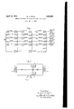
- FIG. 1 shows, by means of a single line diagram, an arrangement embodying my invention
- Fig. 2 represents a type of modu lating means which may be advantageouslyemployed.
- a source of low frequency oscillations which I shall hereinafter term the base frequency
- the base frequency is ems ployed as ameans for synchronizing or maintaining the spacing in the frequency spectrum of the various high frequencyfwaves which are to be produced.
- the desired high frel quency waves ars'in fact developed'from thisV common base frequency.
- the system whereby the desired high frequency oscillations are thus developed comprises, briefly, a plurality of channels, corresponding in number to the number of ,different frequencies which are to be produced, these channels bein g indicated in the drawings by the coefficients of the legends applied to the rectangles thereof.
- Each channel is ini'- tiated by a low harnionic of the common base frequency, which frequency is modulated, in
- the rectangles lTC, 2TC, 5TC represent a plurality oftuned circuits which operfromthe oscillations suppliedv to the conductorll various low harmonics, or multiples, of the 'base frequency supplied to this con- Similarly the circuits 2TC, 3TC, 4TC, 5TC
- X and X2 I have represented a plurality of frequency multipliers, or harmonic generators, connected in cascade.
- These multipliers may be of any suitable construction, such for example as an electron discharge device having tuned grid and anode circuits, and having its grid and anode voltages so adjusted that it operates on a curved portion ofthe characteristic. These multipliers are so adjusted as to produce in their output circuits certain high harmonics of the base frequency.
- the fundamental frequency of .5 K. C.' is supplied to the input of have shown a plurality of modulators'lM,
- v I have shown a filter 1F, 2F, 5F, etc.
- the multiplier X mav be assumed to produce in its output circuit the eighth harmonic of the input frequency or 160 K. C.
- This frequency may then be modulated with each of the side band frequencies which appear in the output circuit of the filters F by means of modulators 1M', 5M', etc.
- the filters F then again eliminate the lower side band or difference frequency resulting from this modulation, thereby producing in the output circuits oscillations having the frequencies 181 K. C., 181.5 K. C., 182 K. C., 182.5 K. C.. 183 K. C., etc., respectively.
- filters F, F and F2 are indicated as being adjusted to eliminate the lower side band frequency, it will of course be apparent that these filters maybe arranged to eliminate the upper side band frequency, or a part of them may be adjusted to eliminate one side lection of the side band frequencies and the ,f
- My invention possesses the advantage that notwithstanding the frequencies produced are relatively close together, the arrangement is such that the filters F, F and F2 may be of any convenient construction and need not be of a kind which is sharply selective to certain frequencies to the exclusion of others.
- the filters F, F and F2 may be of any convenient construction and need not be of a kind which is sharply selective to certain frequencies to the exclusion of others.
- the two side band frequencies which are respectively 21 K. C. and 19 K. C. These frequencies are sufficiently spaced apart to be readily separable by means of an inexpensive filter.
- the 1 K. C. frequency modulated upon the 160 K; C. harmonic an expensive lter would be required to separate the side bands.
- the side bands produced by the modulators 2M, 3M. 4M and 5M are still more widely spaced apart han those produced by modulator 1M.
- filters F and M2 may be of a very inexpensive construction.
- the method of producing a plurality of high frequency oscillations spaced apart in the frequency range by fixed intervals which includes producing oscillations having a low base frequency corresponding lto the minimum interval between frequencies to be produced, producing a plurality of low cies spaced apart in the frequency range by harmonics of said base frequency, producing a plurality of high harmonics of said base frequency s aced ⁇ apart in the frequency range by wi e intervals, modulating the lowest of said high harmonics with each of said low harmonics, selecting a side band frequency produced by modulating said lowest high harmonic with each of said low harmonies, modulating a higher one of said high harmonics with each of said side band frequencies and supplying to load circuits frequencies corresponding to the side band frequencies produced by said last modulation.
- the method of producing a plurality of oscillations spaced apart in the frequency spectrum byvixed intervals which. includes producing a plurality of low harmonics of-a base frequency, and a plurality of high harmonies of said baseQf-requency, modulating of said low harmonic, selectingdesired side 'trum by bands, and modulating each of the higher harmonics in ⁇ succession with a sideband produced by modulation of the next' lower of said high harmonics, said ⁇ high. harmonic frequencies being so chosen with respect to said low harmonic and side band frequencies as to permit eicien't selection of-desiredside quencieafacedapart in the frequency ed intervals,.ofa source of base,"
Landscapes
- Electrostatic Charge, Transfer And Separation In Electrography (AREA)
Description
April 19, 1932. w. A. FITCH 1,854,986
METHOD AND MEANS FOR PRODUCING HIGH FREQUENGIES Filed May 17, 1930 lvehtor: William A. Fitch 13b/MMM His Attorney.
Patented' Apr. 1 9, '1 932f i A. Irren.
.coxrmy, A1 compagnon .or mixen; v 1
vfr
mm mi man@#wma-m j my l Application mea 'laila-19am 1s`rnufv1-rol masas.'l P
i My invention relates to a method and means l for producing'a plurality Yofhigh frequencies which are spaced apart in the frequency spectrum by fixed intervals and it has for one of its objects to produce an improved method ,and means whereby a plurality of fixed high frequencies may be produced, all of which may be included in a narrow portion of the frequency spectrum.
Another object of the invention is to provide a method and means whereby a pluralmay best be understood by reference to the following description taken in connection with. the accompanying drawings, in which Fig. 1 shows, by means of a single line diagram, an arrangement embodying my invention, and Fig. 2 represents a type of modu lating means which may be advantageouslyemployed.
.In accordance with my invent-ion, a source of low frequency oscillations, which I shall hereinafter term the base frequency, is ems ployed as ameans for synchronizing or maintaining the spacing in the frequency spectrum of the various high frequencyfwaves which are to be produced. The desired high frel quency waves ars'in fact developed'from thisV common base frequency.
The system whereby the desired high frequency oscillations are thus developed comprises, briefly, a plurality of channels, corresponding in number to the number of ,different frequencies which are to be produced, these channels bein g indicated in the drawings by the coefficients of the legends applied to the rectangles thereof. Each channel is ini'- tiated by a low harnionic of the common base frequency, which frequency is modulated, in
the first stage of the system upon a high or l*roam .assmivoaf'ro ummm mound j harmonic of the base and 'a defy I sired side band selected.
n the succeeding stage theselected side `band in `each channel is in turn modulated'upon a higher harmonic of the base frequency and a side band is again selected, this 4process being repeated in successivestages untilfthefdes'ired frequencies I are producedl, "Reference may be had tothese stagesof the system bythe exponents of the le ends applied to the drawings.
. n the one line diagrainshowninFig. 1 it maybe assumed thatthe'low,or base, frequency `source. isconneeted to the conductor 1. The rectangles lTC, 2TC, 5TC representa plurality oftuned circuits which operfromthe oscillations suppliedv to the conductorll various low harmonics, or multiples, of the 'base frequency supplied to this con- Similarly the circuits 2TC, 3TC, 4TC, 5TC
pass frequencies of 1.5K.. C., 2 K. C., 2.5 K. C. and 3 K. C. respectively.
At X, X and X2 I have represented a plurality of frequency multipliers, or harmonic generators, connected in cascade. These multipliers may be of any suitable construction, such for example as an electron discharge device having tuned grid and anode circuits, and having its grid and anode voltages so adjusted that it operates on a curved portion ofthe characteristic. These multipliers are so adjusted as to produce in their output circuits certain high harmonics of the base frequency. The fundamental frequency of .5 K. C.'is supplied to the input of have shown a plurality of modulators'lM,
2M, 5Metc. connected to the output of the multiplierX, each of these modulators also being connected to a corresponding tunedv `v ate in the nature of band pass filters to select f tiples are supplied to the grids'in like phase,
as by means of conductors 6 and coupling condensers 7 and 8. In the output circuitv will appear oscillations having a frequency corresponding to the side bands, or to the sum of the two input frequencies and also oscillations correspondingr to the difference of the two input frequencies. The high multiple frequency, or oscillations of the 2O K. C.
frequency, lwill be eliminated in the primary winding of the output transformer 9.
v I have shown a filter 1F, 2F, 5F, etc.,
connected in each of the output circuits of the various modulators 1M, 5M, etc. These filters may be of any suitable low pass or high pass type but in conformance with the legends applied to the drawings these filters may be assumed to be of the high pass type and are so adjusted as to eliminate the lower side band or difference frequency which appears inthe output circuit of each of the modulators. Thus in the output circuit of the different filters F will appear respectively, oscillations having the frequency 21 K. C., 21.5 K. C., 22 K. C., 22.5 K. C. and 23 K. C.
The multiplier X mav be assumed to produce in its output circuit the eighth harmonic of the input frequency or 160 K. C. This frequency may then be modulated with each of the side band frequencies which appear in the output circuit of the filters F by means of modulators 1M', 5M', etc. The filters F then again eliminate the lower side band or difference frequency resulting from this modulation, thereby producing in the output circuits oscillations having the frequencies 181 K. C., 181.5 K. C., 182 K. C., 182.5 K. C.. 183 K. C., etc., respectively. q
If we assume now that the multiplier X2 produces the eighth harmonic of the input frequency, it will be seen that a frequency of 1280 K. C. is produced in its output circuit. This frequency may then be modulated by means of modulators M2 with the frequencies appearing in the output circuits of the filters F. In the output circuit of the modulators M2 'are shown filters ,F2 which similarly eliminate the lower side-band frequencv. Thus in the output circuits of these filters are produced oscillations having frequencies of 1461 K. C.. 1461.5 K. C.. 1462 K. C., 1462.5 K. C.. 1468 K. C., etc., respectively. These oscillations may then be supplied to suitable load circuits, which are' indicated in the drawing as antennae or ernployed in any manner desired.
While in the description given the filters F, F and F2 are indicated as being adjusted to eliminate the lower side band frequency, it will of course be apparent that these filters maybe arranged to eliminate the upper side band frequency, or a part of them may be adjusted to eliminate one side lection of the side band frequencies and the ,f
harmonic frequencies generated by the multipliers X, X and X2. any desired frequency may be produced and these frequencies may be lspaced apart in the frequency range as desired. Similarly if desired oscillations may be supplied from any stage of the system to suitable load circuits.
My invention possesses the advantage that notwithstanding the frequencies produced are relatively close together, the arrangement is such that the filters F, F and F2 may be of any convenient construction and need not be of a kind which is sharply selective to certain frequencies to the exclusion of others. Thus for example in the output circuit of the filter 1M appear the two side band frequencies which are respectively 21 K. C. and 19 K. C. These frequencies are sufficiently spaced apart to be readily separable by means of an inexpensive filter. On the other hand were the 1 K. C. frequency modulated upon the 160 K; C. harmonic, an expensive lter would be required to separate the side bands. The side bands produced by the modulators 2M, 3M. 4M and 5M are still more widely spaced apart han those produced by modulator 1M. For
the same reason the filters F and M2 may be of a very inexpensive construction.
While I have shown a particular embodiment of my invention, it will of course be understood that I do not wish to be limited thereto since many modifications may be made both in the circuit arrangement and in the. instrumentalities employed. l therefore contemplate by the appended claims to cover anv such modifications as fall within the trite spirit and scope of my invention.
What I claim as new and desire to secure by Letters Patent of the United States, is
1. The method of producing a plurality of high frequency oscillations spaced apart in the frequency range by fixed intervals which includes producing oscillations having a low base frequency corresponding lto the minimum interval between frequencies to be produced, producing a plurality of low cies spaced apart in the frequency range by harmonics of said base frequency, producing a plurality of high harmonics of said base frequency s aced` apart in the frequency range by wi e intervals, modulating the lowest of said high harmonics with each of said low harmonics, selecting a side band frequency produced by modulating said lowest high harmonic with each of said low harmonies, modulating a higher one of said high harmonics with each of said side band frequencies and supplying to load circuits frequencies corresponding to the side band frequencies produced by said last modulation.
2. The method of producing a plurality of oscillations having different high frequenv fixed intervals which includes producmg a plurality rof oscillations having frequencies corresponding to certain low multiples of a common base frequency, producing a pluralityof oscillations having frequencies corresponding to certain high multlples of said common base frequency, modulating oscillations having a frequency correspondingvto 'the lowest of said high multiple frequencies with each of said oscillations having said low multiple frequencies, selecting desired side band frequencies resulting from said modulation and modulating oscillations having frequency corresponding to a higher multiple of said base frequency with each of said side band frequencies, whereby oscillations havingfrequencies corresponding to desired side band frequencies resulting from said last modulation are produced, said high multiple frequencies being so chosen with respect to said low multiple and side band fre.-
,quencies as to permiteicient selection of desired side band frequencies resulting from each modulation.
3. The method of producing a plurality of oscillations spaced apart in the frequency spectrum byvixed intervals which. includes producing a plurality of low harmonics of-a base frequency, and a plurality of high harmonies of said baseQf-requency, modulating of said low harmonic, selectingdesired side 'trum by bands, and modulating each of the higher harmonics in `succession with a sideband produced by modulation of the next' lower of said high harmonics, said `high. harmonic frequencies being so chosen with respect to said low harmonic and side band frequencies as to permit eicien't selection of-desiredside quencieafacedapart in the frequency ed intervals,.ofa source of base,"
' frequencyoscillations, means for producing a pluralitygoflow harmonics',zand `a plurality of high harmonics of said base frequency,
means `for modulating the lowest of saidhigh harmonics with each of said low harmoni filtering means for selecting desired side ban frequencies resulting from said modulation, mea-ns for modulating the next higher of said high harmonics with the selected side band frequencies and filtering means for s lecting desired side bands resulting frosaid last modulation, the ratio between t e frequency of each of said high harmonics and the frequencies with which it is modulated being sufiiciently great to ermit eiiicient selection of desired side ban s by saidltering means.
In witness whereof, I have hereto set-my hand this 16th day of May, 1930.
WILLIAM A. FITCH.
the lowest of said high harmonics with each ist
Priority Applications (1)
| Application Number | Priority Date | Filing Date | Title |
|---|---|---|---|
| US453394A US1854986A (en) | 1930-05-17 | 1930-05-17 | Method and means for producing high frequencies |
Applications Claiming Priority (1)
| Application Number | Priority Date | Filing Date | Title |
|---|---|---|---|
| US453394A US1854986A (en) | 1930-05-17 | 1930-05-17 | Method and means for producing high frequencies |
Publications (1)
| Publication Number | Publication Date |
|---|---|
| US1854986A true US1854986A (en) | 1932-04-19 |
Family
ID=23800401
Family Applications (1)
| Application Number | Title | Priority Date | Filing Date |
|---|---|---|---|
| US453394A Expired - Lifetime US1854986A (en) | 1930-05-17 | 1930-05-17 | Method and means for producing high frequencies |
Country Status (1)
| Country | Link |
|---|---|
| US (1) | US1854986A (en) |
Cited By (3)
| Publication number | Priority date | Publication date | Assignee | Title |
|---|---|---|---|---|
| US2433343A (en) * | 1942-03-12 | 1947-12-30 | Int Standard Electric Corp | Multichannel electrical communication system |
| US2768551A (en) * | 1947-01-14 | 1956-10-30 | Baldwin Piano Co | Electronic organ with tremolo |
| US2988710A (en) * | 1958-12-19 | 1961-06-13 | Gen Electric | Digital frequency generator |
-
1930
- 1930-05-17 US US453394A patent/US1854986A/en not_active Expired - Lifetime
Cited By (3)
| Publication number | Priority date | Publication date | Assignee | Title |
|---|---|---|---|---|
| US2433343A (en) * | 1942-03-12 | 1947-12-30 | Int Standard Electric Corp | Multichannel electrical communication system |
| US2768551A (en) * | 1947-01-14 | 1956-10-30 | Baldwin Piano Co | Electronic organ with tremolo |
| US2988710A (en) * | 1958-12-19 | 1961-06-13 | Gen Electric | Digital frequency generator |
Similar Documents
| Publication | Publication Date | Title |
|---|---|---|
| US2624041A (en) | Amplitude modulator of the outphasing type | |
| US1854986A (en) | Method and means for producing high frequencies | |
| US3777271A (en) | Generation of microwave frequency combs with narrow line spacing | |
| US2159595A (en) | Frequency conversion circuits | |
| US2159596A (en) | Frequency conversion circuits | |
| US2916706A (en) | Audio modulator | |
| US2960664A (en) | Wide band noise source | |
| US2879387A (en) | Multi-channel phase locked tone converter | |
| US1719052A (en) | Single-side-band carrier system | |
| US2401481A (en) | High-frequency signal generator | |
| US3235815A (en) | Frequency synthesizer digit selector | |
| US2776373A (en) | Frequency conversion circuits | |
| US3225316A (en) | Phase-shift single side-band modulators | |
| US2553610A (en) | Harmonic amplitude selector for signaling systems | |
| US3312909A (en) | Variable frequency oscillation generators | |
| US2575993A (en) | Multiple carrier transmission system | |
| US2241933A (en) | Utilization of broadcast waves for obtaining high frequency carrier | |
| US2902659A (en) | Modulating system | |
| US2005795A (en) | High frequency multiplex signaling system | |
| US2247544A (en) | Apparatus and process for generating sinusoidal currents | |
| US1978818A (en) | Frequency stabilization | |
| US3027523A (en) | Apparatus for producing a single sideband signal in a sampling system | |
| US2390641A (en) | Multichannel carrier communication system | |
| US2790079A (en) | Multi-channel radio equipment | |
| US2872646A (en) | Transmitter frequency generation system |