US1854985A - Electric lighter for cigars, cigarettes and the like - Google Patents
Electric lighter for cigars, cigarettes and the like Download PDFInfo
- Publication number
- US1854985A US1854985A US419966A US41996630A US1854985A US 1854985 A US1854985 A US 1854985A US 419966 A US419966 A US 419966A US 41996630 A US41996630 A US 41996630A US 1854985 A US1854985 A US 1854985A
- Authority
- US
- United States
- Prior art keywords
- lighter
- heating element
- electric
- unit
- cigars
- Prior art date
- Legal status (The legal status is an assumption and is not a legal conclusion. Google has not performed a legal analysis and makes no representation as to the accuracy of the status listed.)
- Expired - Lifetime
Links
Images
Classifications
-
- F—MECHANICAL ENGINEERING; LIGHTING; HEATING; WEAPONS; BLASTING
- F23—COMBUSTION APPARATUS; COMBUSTION PROCESSES
- F23Q—IGNITION; EXTINGUISHING-DEVICES
- F23Q7/00—Incandescent ignition; Igniters using electrically-produced heat, e.g. lighters for cigarettes; Electrically-heated glowing plugs
Definitions
- This invention relates to electric lighters for cigars, cigarettes and the like, of the type comprising a body portion of insulating material adapted to be secured to a iXed sup- 53 port, as the instrument board of a motor driven vehicle, a lighter unit adapted to be removably supported on said body portion, a heating element of electrical resistant material, electrical contacts and conductors con- ]o' nected in circuit with said heating element, and a switch which controls said circuit.
- a principal object of the invention is to provide an electric lighter of the type specified, of novel construction and arrange- 1'53 ment whereby the switch controlling the electric circuit may be manipulated and the lighter unit removed from the body portion of the lighter conveniently and expeditiously, using one hand only.
- a further object of the invention is to provide a lighter of the type specified, in which the contacts for connecting the heating element electrially will form a guard constructed and arranged to enclose said heating ele- 254 ment thereby preventing accidental contact therewith when the lighter element is sup ported on the base, which might result in the clothing or person of an individual be ⁇ ing burned by contact therewith when the heating element is incandescent, said guard also being constructed to render said heating element visible, whereby a person desiring to use it may know when it is incandescent.
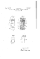
- Fig. 1 is a front view of an electric lighter embodying my invention and improvements.
- Fig. 2 is a sectional view thereof on the line A-B of Fig. 1.
- Fig. 3 is an end view from a position above Fig. 1;
- - Fig. 4 is a detached side view of the lighter unit.
- my improved lighter comprises 419,966, and in Germany January 10, 1929.
- suitable insulating material as bakelite
- opposite ends of the lighter unit 4 are adapted to be removably secured 65 to the projections 2 and 3, respectively, in the following manner: Secured to the projection 2 is a cap 5, which, as shown, is made of sheet metal which is a good conductor of electricity and which comprises a reduced shank portion which closely fits a. hole formed in said projection 2 and is secured therein by a screw which forms part of the binding post 6, as shown. Formed around the open side of the cap 5 is a flanged seat which is adapt- 75 ed to receive and interlock with an annular flange forming part of a member 16 secured in a recess formed in the end of the handle portion of the lighter unit 4 designed to be supported on the projection 2, by screws, as shown, or other suitable means.
- the member 16 is made of sheet metal which is a good conductor of electricity, secured in the open side of which is a heating element 17 made of electrical resistant material, connected electrically as presently described.
- the cap 5 and member 16 are shaped so that when the lighter unit 4 is supported on the base 1, said cap 5 and member 16 Will form a guard 90 which will enclose the heating element 17, thereby preventing unintential contact there* with.
- Fig. 1 see particularly Fig.
- the member 16 is provided with holes or perforations through which said heating element is visible, thus indicating to a user when it is incandescent.
- the means for removably supporting the lighter unit 4 on the proj ecw tion 3 of the base portion of the lighter con- "C5 Sists of a spring-pressed bolt 7 made of metal which is a good conductor of electricity, said bolt being fitted to a bearing formed in said projection 3, so as to be movable endwise therein, and which is adapted to engage a recess 22 formed in the end of the handle portion of the lighter unit 4 designed. to be supported on said projection 3;
- the recess 22 and the end ot' the bolt 7 which engages said recess are tapered, the eXtreme endl of the bolt being rounded; Said bolt is maintained yieldingly in locking position by the spring applied thereto, as shown.
- the electrical contacts and connections of the lighter comprise the binding post 6, the screw forming part thereof by which.v the caip issecured to the projection 2.0i the body portion of thelighter, the cap 5,7the flanged member 16, which is in electrical contact with said cap when the lighter unit is supported on. the body portion of the lighter, the binding post 10 a part of which contacts with the bolt 7., which, as stated, is
- the heating element 17 iselectrically connected at apoint, or points on its periphery. withz the flange of themember 1.6 and. is electricallyconnected at its center by af screw 15, which engages saidheating element centrally and the lower end of which; has threaded engagement* with a hole formed' inthe proximateendzot the contact 12.I As shown,.also,.
- Vthe-underside of the'element 17 rests on and* iszsup'ported by a nut' threaded to the screw 15, as shown.
- the disk. portion of the mem- ⁇ ber 16 necessarily: will? he insulated from the screwV and also froml the upper: end of the conductor 12. ⁇ VVhilemeans for thispurpose are' notl shown or described in detail, such means readily can'besuppliedby skilled electricians Without the exercise of invention.
- the conductors 12 and'13 are adapted to Stbe-electrically connectedl by a suitable switch consisting, as shown, of a spring made of metal, which 1s a goedv conductor of electricity-one endl of which is secured to one of.”
- An electric lighter com rising a base portion of insulating materialphaving spaced projections a. lighter unit comprising a. handle portion of insulating material having a, heating element of electrical resistant material in one end, means for removably mounting said lighter ⁇ unit betweenthe. projections oni the baseportion. o the. lighter' comprising relatively fixed intenlocking parts onv one o'said projections; and on thecnd 0i' the body.-l portionof the lighter unit tov which the heating element is secured, a bolt movahlV- endwise in a hearingl in theA other projection.
- An: electric lighter comprising a base portion of insulating material?, alighten unit comprising a handle portion of i'nsulatingma. terial having a heating elementot ⁇ - eleotniealx resistant material in, one end, means for re,- movably mounting lighter unit ontho base portion. ofl the. lighter comprising nelaf tively fiXedi interlockingl parts on said baaof and on the end of said lighterfunit to' ⁇ which. the ⁇ heatingI element is secured, saidy nterlocking parts being made of sheet material' which-is a goodconductor ofelectricit ormingv an electrode with: which, the heating ⁇ ele ment is inl electric circuit and'. whichA aref shapedl and arranged toenclose said heating element whenl the lighter unit is: operatively engaged with the base portion of the lighten.
- An electric lighter comprising aV base portion of insulating material1, a lighterunit comprising a handle portion of insulating material/havinga heating element: of electric resistant material in one end, and means for removablyV mounting said lighter unit ony the base poi-tion of the lighter comprising' a; 13
Landscapes
- Engineering & Computer Science (AREA)
- Chemical & Material Sciences (AREA)
- Combustion & Propulsion (AREA)
- Mechanical Engineering (AREA)
- General Engineering & Computer Science (AREA)
- Passenger Equipment (AREA)
Description
April 19, 1932. C DOERR SR 1,854,985
ELECTRIC LIGHTER FOR CIGARS, CIGARETTES, AND THE LIKE Filed Jan. lO 1950 Patented Apr. 19, 1932 UNITED STATES PATENT OFFICE ELECTRIC LIGHTER FOR CIGARS, CIGARETTES AND THE LIKE Application led January 10, 1930, Serial No.
This invention relates to electric lighters for cigars, cigarettes and the like, of the type comprising a body portion of insulating material adapted to be secured to a iXed sup- 53 port, as the instrument board of a motor driven vehicle, a lighter unit adapted to be removably supported on said body portion, a heating element of electrical resistant material, electrical contacts and conductors con- ]o' nected in circuit with said heating element, and a switch which controls said circuit.
A principal object of the invention is to provide an electric lighter of the type specified, of novel construction and arrange- 1'53 ment whereby the switch controlling the electric circuit may be manipulated and the lighter unit removed from the body portion of the lighter conveniently and expeditiously, using one hand only.
A further object of the invention is to provide a lighter of the type specified, in which the contacts for connecting the heating element electrially will form a guard constructed and arranged to enclose said heating ele- 254 ment thereby preventing accidental contact therewith when the lighter element is sup ported on the base, which might result in the clothing or person of an individual be` ing burned by contact therewith when the heating element is incandescent, said guard also being constructed to render said heating element visible, whereby a person desiring to use it may know when it is incandescent.
To effect the objects thereof, an electric '354 lighter embodying my invention and improvements, comprises the various features, combinations of features and details of construction hereinafter described and claimed. In thefaccompanying drawings, in which il the invention is fully illustrated,
Fig. 1 is a front view of an electric lighter embodying my invention and improvements. Fig. 2 is a sectional view thereof on the line A-B of Fig. 1.
Fig. 3 is an end view from a position above Fig. 1; and
- Fig. 4 is a detached side view of the lighter unit.
' yDescribing the invention with reference to the drawings, my improved lighter comprises 419,966, and in Germany January 10, 1929.
a base portion 1 made of suitable insulating material, as bakelite, adapted to be secured to a suitable support, as the instrument board of a motor vehicle, not shown, as by screws inserted through holes provided for the pur- 55 pose.
Formed at the ends of that side of said body portion which is exposed when said lighter is installed for use, are projections 2 and 3 between which a lighter unit 4 com- 80 prising a handle portion also made of insulating material, preferably bakelite, is adapted to be removably supported.
As shown, opposite ends of the lighter unit 4 are adapted to be removably secured 65 to the projections 2 and 3, respectively, in the following manner: Secured to the projection 2 is a cap 5, which, as shown, is made of sheet metal which is a good conductor of electricity and which comprises a reduced shank portion which closely fits a. hole formed in said projection 2 and is secured therein by a screw which forms part of the binding post 6, as shown. Formed around the open side of the cap 5 is a flanged seat which is adapt- 75 ed to receive and interlock with an annular flange forming part of a member 16 secured in a recess formed in the end of the handle portion of the lighter unit 4 designed to be supported on the projection 2, by screws, as shown, or other suitable means. The member 16 is made of sheet metal which is a good conductor of electricity, secured in the open side of which is a heating element 17 made of electrical resistant material, connected electrically as presently described. In the preferable construction shown, also, the cap 5 and member 16 are shaped so that when the lighter unit 4 is supported on the base 1, said cap 5 and member 16 Will form a guard 90 which will enclose the heating element 17, thereby preventing unintential contact there* with. As shown, also, see particularly Fig.
4, the member 16 is provided with holes or perforations through which said heating element is visible, thus indicating to a user when it is incandescent.
As shown, also, the means for removably supporting the lighter unit 4 on the proj ecw tion 3 of the base portion of the lighter, con- "C5 Sists of a spring-pressed bolt 7 made of metal which is a good conductor of electricity, said bolt being fitted to a bearing formed in said projection 3, so as to be movable endwise therein, and which is adapted to engage a recess 22 formed in the end of the handle portion of the lighter unit 4 designed. to be supported on said projection 3;
As shown, the recess 22 and the end ot' the bolt 7 which engages said recess, are tapered, the eXtreme endl of the bolt being rounded; Said bolt is maintained yieldingly in locking position by the spring applied thereto, as shown. p
As shoWn, the electrical contacts and connections of the lighter comprise the binding post 6, the screw forming part thereof by which.v the caip issecured to the projection 2.0i the body portion of thelighter, the cap 5,7the flanged member 16, which is in electrical contact with said cap when the lighter unit is supported on. the body portion of the lighter, the binding post 10 a part of which contacts with the bolt 7., which, as stated, is
Ymade of metal which is a good conductor of electricity, electricL conductors 12 andl 13 mounted in. fixed position in an axial hole formed through the= handle portion of the lighter unitl 4, adjacent ends of said conductors being separatedby insulating material, as shown.k at 14.
The heating element 17 iselectrically connected at apoint, or points on its periphery. withz the flange of themember 1.6 and. is electricallyconnected at its center by af screw 15, which engages saidheating element centrally and the lower end of which; has threaded engagement* with a hole formed' inthe proximateendzot the contact 12.I As shown,.also,.
Vthe-underside of the'element 17 rests on and* iszsup'ported by a nut' threaded to the screw 15, as shown. The disk. portion of the mem-` ber 16 necessarily: will? he insulated from the screwV and also froml the upper: end of the conductor 12.` VVhilemeans for thispurpose are' notl shown or described in detail, such means readily can'besuppliedby skilled electricians Without the exercise of invention.
The conductors 12 and'13 are adapted to Stbe-electrically connectedl by a suitable switch consisting, as shown, of a spring made of metal, which 1s a goedv conductor of electricity-one endl of which is secured to one of."
saidv conductors-as shown, the conductor 13-the free end of which is adapted to be e depressed andk the lighter unit 4 moved down against the force of the spring applied to the locking bolt 7 simultaneously and with the use of one hand only; and that, as mounted for use, the heating element 17 iS enclosed, thereby preventing unintentional Contact therewith, while at the same time it is Visible` sothat a person using. it may know whentit is in condition for use.
I claim l. An electric lighter com rising a base portion of insulating materialphaving spaced projections, a. lighter unit comprising a. handle portion of insulating material having a, heating element of electrical resistant material in one end, means for removably mounting said lighter` unit betweenthe. projections oni the baseportion. o the. lighter' comprising relatively fixed intenlocking parts onv one o'said projections; and on thecnd 0i' the body.-l portionof the lighter unit tov which the heating element is secured, a bolt movahlV- endwise in a hearingl in theA other projection. on the base adaptedto interlockwith a Recess formed in the end of the body portion of Said lighter unit other than., thatl in; which. the heating; element issecured', ay spring applied to said bolt for maintaining, it yieldingly in locling'position', contacts and: conductors for connecting the heating; element electrically., and` a switch; on said lighterunit which controls said circuitpermitting said switehtofbe manipulated; and.y said lighter unit to be,` re-y mfved fromthe; base by the usev of one hand on y.
2. An: electric lighter comprising a base portion of insulating material?, alighten unit comprising a handle portion of i'nsulatingma. terial having a heating elementot`- eleotniealx resistant material in, one end, means for re,- movably mounting lighter unit ontho base portion. ofl the. lighter comprising nelaf tively fiXedi interlockingl parts on said baaof and on the end of said lighterfunit to'` which. the` heatingI element is secured, saidy nterlocking parts being made of sheet material' which-is a goodconductor ofelectricit ormingv an electrode with: which, the heating` ele ment is inl electric circuit and'. whichA aref shapedl and arranged toenclose said heating element whenl the lighter unit is: operatively engaged with the base portion of the lighten.
3. An electric lighter as specified? in claim- 2, in which an interlocking part for mountingthe end of the lighter tofwhichzthe heating element is securedl is provided with perforations through which the heating element is visible when enclosed by said lnterlocking parts.
4. An electric lighter comprising aV base portion of insulating material1, a lighterunit comprising a handle portion of insulating material/havinga heating element: of electric resistant material in one end, and means for removablyV mounting said lighter unit ony the base poi-tion of the lighter comprising' a; 13
name.
CARL DoERR, sen.
Applications Claiming Priority (1)
| Application Number | Priority Date | Filing Date | Title |
|---|---|---|---|
| DE1854985X | 1929-01-10 |
Publications (1)
| Publication Number | Publication Date |
|---|---|
| US1854985A true US1854985A (en) | 1932-04-19 |
Family
ID=7746172
Family Applications (1)
| Application Number | Title | Priority Date | Filing Date |
|---|---|---|---|
| US419966A Expired - Lifetime US1854985A (en) | 1929-01-10 | 1930-01-10 | Electric lighter for cigars, cigarettes and the like |
Country Status (1)
| Country | Link |
|---|---|
| US (1) | US1854985A (en) |
Cited By (2)
| Publication number | Priority date | Publication date | Assignee | Title |
|---|---|---|---|---|
| US2445664A (en) * | 1946-02-27 | 1948-07-20 | Collins Radio Co | Multifrequency generating and selecting system |
| US2938988A (en) * | 1955-08-15 | 1960-05-31 | David C Mccutcheon | Electrical ignitor device for solid fuels |
-
1930
- 1930-01-10 US US419966A patent/US1854985A/en not_active Expired - Lifetime
Cited By (2)
| Publication number | Priority date | Publication date | Assignee | Title |
|---|---|---|---|---|
| US2445664A (en) * | 1946-02-27 | 1948-07-20 | Collins Radio Co | Multifrequency generating and selecting system |
| US2938988A (en) * | 1955-08-15 | 1960-05-31 | David C Mccutcheon | Electrical ignitor device for solid fuels |
Similar Documents
| Publication | Publication Date | Title |
|---|---|---|
| US1854985A (en) | Electric lighter for cigars, cigarettes and the like | |
| US2014054A (en) | Electric lamp | |
| US20180266685A1 (en) | Electronic Cigar Lighter | |
| US2030011A (en) | Electrically-operated cigarette lighter | |
| US2516843A (en) | Cigar and cigarette lighter | |
| US3134007A (en) | Electric hot plate stove | |
| US2454024A (en) | Combination electric receptacle and fuse | |
| US2065307A (en) | Electric flashlight | |
| US925412A (en) | Electric testing instrument. | |
| US1683992A (en) | Circuit interrupter and socket | |
| US2558441A (en) | Electrical cigar or cigarette lighter | |
| US2630539A (en) | Cigar lighter knob light | |
| US2846644A (en) | Combination flashlight and circuit tester | |
| US1732784A (en) | Cigar lighter | |
| US2580698A (en) | Electric hot plate | |
| USRE23435E (en) | Cigar and cigarette lighter | |
| US3315207A (en) | Electrical resistance battery handle | |
| US1826576A (en) | Lighter fob | |
| US2122962A (en) | Cigar lighter igniter unit | |
| US2554742A (en) | Electric cigarette lighter | |
| US1219903A (en) | Electric sealing-wax-applying device. | |
| US2272931A (en) | Wire burning unit | |
| US2037027A (en) | Lighter | |
| US1796293A (en) | Fan base | |
| US1480011A (en) | Jakes h |