US1854981A - Folding support - Google Patents
Folding support Download PDFInfo
- Publication number
- US1854981A US1854981A US455993A US45599330A US1854981A US 1854981 A US1854981 A US 1854981A US 455993 A US455993 A US 455993A US 45599330 A US45599330 A US 45599330A US 1854981 A US1854981 A US 1854981A
- Authority
- US
- United States
- Prior art keywords
- support
- top members
- members
- frames
- braces
- Prior art date
- Legal status (The legal status is an assumption and is not a legal conclusion. Google has not performed a legal analysis and makes no representation as to the accuracy of the status listed.)
- Expired - Lifetime
Links
- 210000005069 ears Anatomy 0.000 description 4
- XAGFODPZIPBFFR-UHFFFAOYSA-N aluminium Chemical compound [Al] XAGFODPZIPBFFR-UHFFFAOYSA-N 0.000 description 2
- 229910052782 aluminium Inorganic materials 0.000 description 2
Images
Classifications
-
- A—HUMAN NECESSITIES
- A47—FURNITURE; DOMESTIC ARTICLES OR APPLIANCES; COFFEE MILLS; SPICE MILLS; SUCTION CLEANERS IN GENERAL
- A47B—TABLES; DESKS; OFFICE FURNITURE; CABINETS; DRAWERS; GENERAL DETAILS OF FURNITURE
- A47B3/00—Folding or stowable tables
- A47B3/08—Folding or stowable tables with legs pivoted to top or underframe
- A47B3/083—Folding or stowable tables with legs pivoted to top or underframe with foldable top leaves
Definitions
- This invention relates to a folding support and particularly to a type of support that is adapted to support a casket.
- the object of the invention is to provide a support of light, strong and simple construci folded to its open position, thereafter making it impossible for the support to collapse without first actuating the locking means to unlock the top members.
- Another object of the invention is to provide diagonally positioned bracing means for the lower portion of the support, said bracing means being actuated automatically to break the bracing effect when the adjacent abutting portions of the top members are moved upwardly in folding the support.
- the invention consists in a support as set forth in the following specification and particularly as pointed out in the claims thereof.
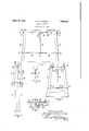
- Fig. 1 represents a front elevation of a support embodying my invention, said support being located in its open position.
- Fig. 2 is a side elevation of the support.
- Fig. 3 is a front elevation illustrating the 7 support in its collapsed or folded position.
- Fig. 4 is a detail sectional view illustrating the manner in which the operating rod for the diagonal braces is connected to one of the top members.
- Fig. 5 is a detail sectional elevation illusgrating the locking means for the top memers.
- 6 represents the side frames of the support, each of said frames being preferably constructed in a single piece of cast aluminum. Pivotally attached to each side frame 6 at the top thereof is a top member 7 also constructed in a single piece BOSTON, MASSACHUSETTS, A CORPORATION OF MASSACHU- SUPPORT 1930. Serial No. 455,993.
- top members 7 have ears 8 formed integral therewith, which co-- operate with ears 9'formed integral with the frames 6 and said earsare connectedtogether by meansof a pivotal pin 10.
- the cars 8 and 9 are so positioned upon the top members 7 and side frames 6 respectively that when the top members are located in their openposition that they will rest in a horizontal position with their lower edges supported upon the top edge of the frame 6.:
- the top members 7 are pivotallyv attached one to another at the center of the support by means of pivotal pins 11 which project through co-operating ears 12 which are provided upon the top members.
- the side frames 6 are strongly braced adjacent to the bottom thereof by a plurality of braces 13, of which there are four in number, positioned diagonally.
- One end of each brace 13 is pivotally attached at 14 to a corner portion of r the frame 6 and all of the'braces arepivotally attached together at 15, the pivotal point be ing located in a transverse plane whichpasse'sf through the center of the support and which also includes the pivots 11 of the top imem bers 7.
- the braces 13 are operatively con-- nected to one of the top members 7 by means of a rod 16, the lower end of which is co axially pivoted at 15 to the inner ends of the braces 13. At its upper endthe rod 16 is pivotally attached at 17 to an ear 18 which is formed integral with one of the top members 7 and the axis of the pivot 17 is co-axial with the axes of the pivots 11 of the top members 7. d
- the supportsof this invention are used in pairs, each support being insertedbeneath an end portion of a casket and both of these supports are held spacedapart by any suitable form of spacing means, and when the supports are located in their open position, the top members 7 are locked securely'together by the locking mechanism and when said top members are so locked the lower pbrtionsf ofthe side :frames 6: 211'6 effectively braceId'and it is impossible to break the pivotalnonnection15 by means of which the brace, members13 are joined; together.
Landscapes
- Assembled Shelves (AREA)
- Carriages For Children, Sleds, And Other Hand-Operated Vehicles (AREA)
Description
April 19, 1932. G. w. CAVERLY FOLDING SUPPORT Filed May 27, 1930 fivuen/zior/ Gear 6 WOcLUerZ/y.
Patented Apr. 19, 1932 UNITED STATES PATENT OFFICE GEORGE W. CAVERLY, OF BOSTON, MASSACHUSETTS, ASSIGNOR TO JOSEPH S. WATER- MAN & SONS INC., OF
SETTS 4 FOLDING 7 Application filed May 27,
This invention relates to a folding support and particularly to a type of support that is adapted to support a casket.
The object of the invention is to provide a support of light, strong and simple construci folded to its open position, thereafter making it impossible for the support to collapse without first actuating the locking means to unlock the top members.
Another object of the invention is to provide diagonally positioned bracing means for the lower portion of the support, said bracing means being actuated automatically to break the bracing effect when the adjacent abutting portions of the top members are moved upwardly in folding the support.
The invention consists in a support as set forth in the following specification and particularly as pointed out in the claims thereof.
Referring to the drawings:
Fig. 1 represents a front elevation of a support embodying my invention, said support being located in its open position.
Fig. 2 is a side elevation of the support.
Fig. 3 is a front elevation illustrating the 7 support in its collapsed or folded position.
Fig. 4 is a detail sectional view illustrating the manner in which the operating rod for the diagonal braces is connected to one of the top members.
Fig. 5 is a detail sectional elevation illusgrating the locking means for the top memers.
Like numerals refer to like parts throughout the several views of the drawings.
In the drawings, 6 represents the side frames of the support, each of said frames being preferably constructed in a single piece of cast aluminum. Pivotally attached to each side frame 6 at the top thereof is a top member 7 also constructed in a single piece BOSTON, MASSACHUSETTS, A CORPORATION OF MASSACHU- SUPPORT 1930. Serial No. 455,993.
of cast aluminum. The top members 7 have ears 8 formed integral therewith, which co-- operate with ears 9'formed integral with the frames 6 and said earsare connectedtogether by meansof a pivotal pin 10. The cars 8 and 9 are so positioned upon the top members 7 and side frames 6 respectively that when the top members are located in their openposition that they will rest in a horizontal position with their lower edges supported upon the top edge of the frame 6.:
The top members 7 are pivotallyv attached one to another at the center of the support by means of pivotal pins 11 which project through co-operating ears 12 which are provided upon the top members. The side frames 6 are strongly braced adjacent to the bottom thereof by a plurality of braces 13, of which there are four in number, positioned diagonally. One end of each brace 13 is pivotally attached at 14 to a corner portion of r the frame 6 and all of the'braces arepivotally attached together at 15, the pivotal point be ing located in a transverse plane whichpasse'sf through the center of the support and which also includes the pivots 11 of the top imem bers 7. The braces 13 are operatively con-- nected to one of the top members 7 by means of a rod 16, the lower end of which is co axially pivoted at 15 to the inner ends of the braces 13. At its upper endthe rod 16 is pivotally attached at 17 to an ear 18 which is formed integral with one of the top members 7 and the axis of the pivot 17 is co-axial with the axes of the pivots 11 of the top members 7. d
The mechanism for automatically locking the top members 7 in their open position thereby holding the entire supportin its ing the latch 22 to the catch 19, and a fiat spring 25 which is attached to one of the ears 12 engages the latch 22 in a manner to normally hold the notched portion 24 of the latch 22 in engagement with the notched finger ofthecatch-lQ. a
The supportsof this invention are used in pairs, each support being insertedbeneath an end portion of a casket and both of these supports are held spacedapart by any suitable form of spacing means, and when the supports are located in their open position, the top members 7 are locked securely'together by the locking mechanism and when said top members are so locked the lower pbrtionsf ofthe side :frames 6: 211'6 effectively braceId'and it is impossible to break the pivotalnonnection15 by means of which the brace, members13 are joined; together. I
; nillhenit is desired to collapse the support and foldthe same into the-position illustrated lliFlg-'.:=3, the latches 22 are actuated against the tension of the springs 25and-the:notched pQI'tlOHSi 24-of said-latches are disengaged from the notched fingers 20 of the catches 19.
The adjacent abutting portions ;of the top members. 7= are then grasped and-pulled upajrdly, pullingthe rod 16 upwardly and breaking the pivotalkjointulii which connects the braces 13 together, and a continued upward movement of thejadjacent portions OffthQ tOPJHBHIbB I'S:11 willrcause all of the parts to be folded intothe position illustrated in,,Fig.3.--
4 When the support is movedifrom its foldlike comprising two side frames, two top frames of like dimensions pivotally connected to one another along their inner edges and to the upper ends of the side frames at their outer edges, diagonal bracing members pivotally connectedadjacent the lower ends of the side frames and at opposite sides thereof, and pivotallyjoined intermediate the side frames at a common meeting point, a rod GEORGE W. CAVERLY.
ereunto Set 7 edto-ifts-open position, as the adjacent por- V tions of the top members 7 close toward each otheiyrthe curved extremity of the notched finger20 engages thecurved extremity of the u notched portion 24 ofthe latch 22 and the lattenwillyield sufliciently upon its pivot 23 to allow the notched finger -20 to pass beyond the-extremityof the notched portion 24; and theisp-ring 25 will finally-move the latch 22 to cause the-portion 24 thereof to interlock with thegport-ion 20 :ofrthecatchnxlt will then be impossible to again collapse the support until the locking means is again actu- Iclaim-r w 1. A folding support for caskets and the like eomprisingrtwoside frames, two top frames oflike dimensions pivotally connectedto'one another along their inner edgesand to the upper ends of the sideframes at their outer edges, diagonal bracing members pivotall-ylconnected adjacent-the lower ends of the side frames-and at opposite sides thereof and pivotally: joined intermediate, the side "framesdatqa icommon meeting-point, and a rod interconnecting the diagonal braces and top;members at their pivotal axes to cause the topinembers and braces to move in unison When-the support is opened or closed.
2. folding support-for caskets and the
Priority Applications (1)
| Application Number | Priority Date | Filing Date | Title |
|---|---|---|---|
| US455993A US1854981A (en) | 1930-05-27 | 1930-05-27 | Folding support |
Applications Claiming Priority (1)
| Application Number | Priority Date | Filing Date | Title |
|---|---|---|---|
| US455993A US1854981A (en) | 1930-05-27 | 1930-05-27 | Folding support |
Publications (1)
| Publication Number | Publication Date |
|---|---|
| US1854981A true US1854981A (en) | 1932-04-19 |
Family
ID=23811008
Family Applications (1)
| Application Number | Title | Priority Date | Filing Date |
|---|---|---|---|
| US455993A Expired - Lifetime US1854981A (en) | 1930-05-27 | 1930-05-27 | Folding support |
Country Status (1)
| Country | Link |
|---|---|
| US (1) | US1854981A (en) |
Cited By (5)
| Publication number | Priority date | Publication date | Assignee | Title |
|---|---|---|---|---|
| US2725268A (en) * | 1954-08-12 | 1955-11-29 | Merlin G Pierson | Drop-leaf table |
| US2766089A (en) * | 1953-01-02 | 1956-10-09 | Harold R Nielsen | Portable folding table with lock means |
| US2880011A (en) * | 1956-07-27 | 1959-03-31 | Peterson Mfg Co A E | Toggle member |
| US20040226491A1 (en) * | 2003-05-16 | 2004-11-18 | Ching-Fei Chen | Folding structure of a foldable framework |
| US20240081521A1 (en) * | 2021-06-15 | 2024-03-14 | Lifetime Products, Inc. | Locking mechanism for a folding table |
-
1930
- 1930-05-27 US US455993A patent/US1854981A/en not_active Expired - Lifetime
Cited By (6)
| Publication number | Priority date | Publication date | Assignee | Title |
|---|---|---|---|---|
| US2766089A (en) * | 1953-01-02 | 1956-10-09 | Harold R Nielsen | Portable folding table with lock means |
| US2725268A (en) * | 1954-08-12 | 1955-11-29 | Merlin G Pierson | Drop-leaf table |
| US2880011A (en) * | 1956-07-27 | 1959-03-31 | Peterson Mfg Co A E | Toggle member |
| US20040226491A1 (en) * | 2003-05-16 | 2004-11-18 | Ching-Fei Chen | Folding structure of a foldable framework |
| US20240081521A1 (en) * | 2021-06-15 | 2024-03-14 | Lifetime Products, Inc. | Locking mechanism for a folding table |
| US12285100B2 (en) * | 2021-06-15 | 2025-04-29 | Lifetime Products, Inc. | Locking mechanism for a folding table |
Similar Documents
| Publication | Publication Date | Title |
|---|---|---|
| US2747957A (en) | Foldable sectional top table | |
| US1854981A (en) | Folding support | |
| DE1672296U (en) | PACKAGING CONTAINER. | |
| US1756775A (en) | Extensible fastening | |
| US2358883A (en) | Picnic outfit | |
| US2755153A (en) | Folding sectional top table | |
| US1444569A (en) | Legged article | |
| US2005715A (en) | Folding chair | |
| US2185588A (en) | Tent | |
| US2153508A (en) | Hinged ventilator of the hopper type | |
| US2131594A (en) | Table | |
| US2149059A (en) | Umbrella stick | |
| US1728573A (en) | Chair | |
| US1971783A (en) | Folding lawn chair | |
| US2703741A (en) | Collapsible table | |
| US1924223A (en) | Table | |
| US2153538A (en) | Article holding foldable box | |
| US2574303A (en) | Foldable case, box, or container | |
| US1985284A (en) | Folding table | |
| US2243018A (en) | Table | |
| US2117430A (en) | Prayer rail | |
| DE632762C (en) | Foldable console for wall tables, shelves, etc. like | |
| US2114725A (en) | Baby carriage | |
| US1859121A (en) | Automatic folding table | |
| US2045931A (en) | Card table |