US1854967A - Railway traffic controlling apparatus - Google Patents
Railway traffic controlling apparatus Download PDFInfo
- Publication number
- US1854967A US1854967A US399776A US39977629A US1854967A US 1854967 A US1854967 A US 1854967A US 399776 A US399776 A US 399776A US 39977629 A US39977629 A US 39977629A US 1854967 A US1854967 A US 1854967A
- Authority
- US
- United States
- Prior art keywords
- relay
- switch
- signal
- contact
- indication
- Prior art date
- Legal status (The legal status is an assumption and is not a legal conclusion. Google has not performed a legal analysis and makes no representation as to the accuracy of the status listed.)
- Expired - Lifetime
Links
- 238000004804 winding Methods 0.000 description 6
- 101150087426 Gnal gene Proteins 0.000 description 4
- 230000007935 neutral effect Effects 0.000 description 3
- 241001481828 Glyptocephalus cynoglossus Species 0.000 description 2
- 101100465000 Mus musculus Prag1 gene Proteins 0.000 description 1
- UIIMBOGNXHQVGW-UHFFFAOYSA-M Sodium bicarbonate Chemical compound [Na+].OC([O-])=O UIIMBOGNXHQVGW-UHFFFAOYSA-M 0.000 description 1
- 150000001768 cations Chemical class 0.000 description 1
- 230000004048 modification Effects 0.000 description 1
- 238000012986 modification Methods 0.000 description 1
Images
Classifications
-
- B—PERFORMING OPERATIONS; TRANSPORTING
- B61—RAILWAYS
- B61L—GUIDING RAILWAY TRAFFIC; ENSURING THE SAFETY OF RAILWAY TRAFFIC
- B61L7/00—Remote control of local operating means for points, signals, or track-mounted scotch-blocks
- B61L7/06—Remote control of local operating means for points, signals, or track-mounted scotch-blocks using electrical transmission
- B61L7/08—Circuitry
- B61L7/081—Direct line wire control
Definitions
- the reference character D designates a railway track which is provided with a switch A leading into another track E.
- the switch A is operated by a mechanism M of any suitable type, and this mechanism is in turn controlled by a switch control relay R As here shown, this relay is of the polarized type, that is, it is selectively responsive to the polarity of the current by which it is energized.
- Tratfic over the switch A is controlled 'by signals S S S and S. These signals are controlled by a polarized signal control relay R
- the switch A operates a pole-changer P, which pole-changer in turn controls a switch repeating relay A so that this relay is energized in normal or reverse direction accordas the switch A is in the normal or the reverse position.
- the portions of tracks D and E associated with the switch A are provided with a track circuit comprising the usualtrack battery 13 and the usual track relay T.
- a switch control lever L for the control of the switch A, and a signal control lever L for the control of the signal S.
- a switch indication relay I and a signal indication relay I which relays control indication lamps F, G and OS, as will hereinafter appear.
- a battery C is located in the interlocking tower, and anthe lever L to reverse other battery G is located adjacent the switch A.
- the switch A is in its normal position, and all of the signals S are in their stop positions; Relay R is energized for reasons which'will appear hereinafter, and relay-R is de-energized.
- Theswitch indication relay I will then be energized by current of reverse polarity, the circuit being from the lower terminal of battery C through polar contact '8 and front neutral contact 90f relayA front contact 10 of track relayT, front point of contact 11 of'relay R line wire Y, normal contact 12 ofsignallever L the winding of relay'IBand line wire Onto the middle point of battery-C This will cause polar contact 29 of relay I to swing to the right, whereupon a reverse switch indication lamp F will be lighted by virtuev of. a-
- G A-stop indication lamp G .will then be'lightthe left-hand terminal of battery When i this has been ed by virtue of a circuit which C through front contactBO of relay I polar contact 31 of this relay in the left-hand position, and
- signal indication relay I will become energized 1n the reverse direction, the circuit being from the lower terminal of battery C through wire 28, contact 23 on signal S contact 22 on si nal 3*, front pointof contact 4 ofrela-y R line wire X,signal' lever contact 26,.relay I and line wire 0 to themiddle terminaloi' battery O Relay I will then be energized insuch direction thatits polar contact 31 will swingto the right, thereby causingua proceed lamp G to become, lighted: by virtue of a. circuit which will be obvious from the'fdrawing. The lighting oi'f'this lamp will indicate tothe operator that signal S has responded by moving to the proceed-position.
- theswitch indication relay I will bode-energized, because its circuit will be' open at contact 12 of lever L ⁇ Vhen a train enters the track section it will cause the signal to return to the stop position, because of the usual track relay control, which is not shown in the drawing, and this will close the reverse indication circuit for relay I at all points except front contact 21 of track relay T. It follows that relay I will remain in its tie-energized condition until the train passes out of the track section,
- track relay T will become ener-' gized and relay I will become energized in the reverse direction.
- both branches of the circuit for the OS lamp will be opened, so that this lamp will be extinguished to indicate to the operator that a train has accepted the signal.
- relay I will become energized, so that the OS lamp will be lighted.
- wire 4 is a C0111- bined switch control and signal indication wire
- wireY is a combined signal control'and switch indication wire
- wire O is a common wire.
- Assumswitch control relay a signal control relay, a swich control lever, a signal control level, a switch indication relay, a signal indication relay, a track relay, a switch repeater relay, a combined switch control and signal indication wire X, a combined signal control and switch indication wire Y, a common wire O, a circuit for said switch control relay including a normal signal lever-contact and'a' back contact of said signal control relay as well as said wires X and O, means operated by said switch lever for supplying current of normal or reverse polarity to said switch relay circuit, a circuit for said signal control relay including a back contact of said switch control relay and said wires Y and O, means operated by said signal lever'for supplying current of normal or reverse polarity to'said signal relay ciruit, a circuit for'said switch indication relay including a front contact ofsaid switch repeater relay and a front contact of said track relay as well as a front contact of said switch vcontrol relay and a normal contact of said signal lever and
- a railway switch signalsv governlng traffic over said sW1tch, a switch control relay, a signal control relay, a switch control lever, a signal control lever, a switch indication relay, a signal indication relay, a track relay, a switch repeater relay, a combined switch control and signal indication wire X, a combined signal control and switch indication wire Y, a common wire O, a ClIClllt' for said switch control relay including a normal signal lever contact and a back contact of said signal control relay as well as said wires X and O, means operated by said switch lever for supplying current of normal or reverse polarity to saidswitch relay circuit, a circuit for said'signal control relay including a back contact of said switch control relay and said wires Y and O, means operated by said si nal lever for supplying current of normal or reverse polarity'to.
- said signal relay circuit a circuit for said switch indication relay including a frontcontact of said switch repeater relay and a front contact of said track relay as well as a'front contact of said switch control relay and a normal" contact of said signal lever and said wires Y and O, means operated by said switch repeater relay for supplying current of nor-' ials c crever ep larity co-sai witch nd 10a t e clay-cir uit, a c rcui f sa d signa 1217 r ayi i iingi a ront; o ac of s gnal CQntrolzrclayand airi ht or a leftnta t s id gnal: l er.- an a es X; 9.
- switch control relay asignal control relay
- switch control relay are aswitchcontrollever, a signal control lever
- a switch, indication, relay, 7 a signal indication relay,.a co1nbined switch control. and signal indicationwire X,.a combined signal.
- control and switchiindication wireY a common wire Q a circuit for said switchcontrol relay in: cl iding normal. signal lever. contact and a back contact of, said signal control relay as well; as said wires X and. O, mean-sroperated by said, switch lever for supplyingfcurrent of normal or reverse polarity to said switch relay-circuit, a circuit forsaid signal; control relay including a back contactof saidswitch central e ay, a d a d-w r nd 0, m s operated. by.
- said signal lever for supplying cur-rent ofinormal or reverseipolarity toosaid signa l, rela y. circuit, .a circuit vtor said switch ind cation relay including a normal s gnal lever contact andsaid wiresY and O,cmeans controlled; by said switch for sunplyingcurrent; oftnorn al; or reverse polarity, to said switch indication vrelay circuit, a circuit for said s gnal nd cation-relay including a rightor a, left cont-acton said-signal lever and said wires X and.
- O meanscontrolled by said sigsupplying current ofnormal or reverse-pclarity v to (said signal indication relay circuit, and indication devices controlled by aid. i d a i0n:relays.
- a section of railway track including a switch, a signal governing trafiic over said switch, a; track circuit; for said section includingra trackrelay, a switch indication circuit controlled by said switch and by said track-relay, a signal indication circuit controlledby saidsigna-l and by said track relay, switch indication Vmeans controlled by said switch indication circuit, sig
- nal indication means controlled by said sigcontactsof-both; said; switch indication-relay;
Landscapes
- Engineering & Computer Science (AREA)
- Mechanical Engineering (AREA)
- Train Traffic Observation, Control, And Security (AREA)
Description
April 19, 1932. H c, v ssE 1,854,967 I RAILWAY TRAFFIC CONTROLLING APPARATUS Original Filed Oct. 15, 1929 INVENTOR-Z )7. C. Vnntassel,
Patented Apr. 19 I932 UNITED, STATES PATENT, OFFICE HARRY C. VANTASSEL, 0F WILKINSBIJ 'RG, PENNSYLVANIA, ASSIGNOR TO THE UNION SWITCH & SIGNALCOMPANY, OF SWISSVALE,PENNSYLVANIA, A CORPORATION OF PENNSYLVANIA RAILWAY TRAFFIC conrnonrmq APPARATUS Application filed October 15, 1929, Serial No. 399,776. Renewed December 22, 1930.
out the novel features thereof in claims.
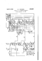
The accompanying drawing is a diagrammatlc view lllustratingone form of apparatus embodying my invention.
Referring to the drawing, the reference character D designates a railway track which is provided with a switch A leading into another track E. The switch A is operated by a mechanism M of any suitable type, and this mechanism is in turn controlled by a switch control relay R As here shown, this relay is of the polarized type, that is, it is selectively responsive to the polarity of the current by which it is energized.
Tratfic over the switch A is controlled 'by signals S S S and S. These signals are controlled by a polarized signal control relay R The switch A operates a pole-changer P, which pole-changer in turn controls a switch repeating relay A so that this relay is energized in normal or reverse direction accordas the switch A is in the normal or the reverse position.
The portions of tracks D and E associated with the switch A are provided with a track circuit comprising the usualtrack battery 13 and the usual track relay T.
Located at a remote point, such as an interlocking tower or a dispatchers ofiice, is a switch control lever L for the control of the switch A, and a signal control lever L for the control of the signal S. Associated with these levers are a switch indication relay I and a signal indication relay I which relays control indication lamps F, G and OS, as will hereinafter appear. A battery C is located in the interlocking tower, and anthe lever L to reverse other battery G is located adjacent the switch A. y
As shown in the drawing, the switch A is in its normal position, and all of the signals S are in their stop positions; Relay R is energized for reasons which'will appear hereinafter, and relay-R is de-energized.
I will assume that the operator desires to re-,
verse the switch A. To do this, he will move position, thereby supplying current of reverse polarity to relay R, the circuitbeing from the right-hand terminal of battery C through switch lever contact 1, normal signal lever contact 3, line wire X, back point of contact 4 of relay R the winding of relay R and a common wire 0 to the middle point of battery C The polar contacts of relay R will then swing to the right, whereupon current of reverse polarity will be supplied to the switch I operating mechanism M, the circuit being from terminal B of a suitable source of current, through front neutral contact 5 of relay R right-hand point of polar contact 6, op-' crating mechanism M, and the right-hand point of polar contact 7 toterminal 0. Ourrent of this polarity will, cause themechanism M to operatein such manner as to move the switch A to its reverse position Whenrthis has been accomplished, polechanger P will reverse, thereby supplying current of reverse polarity to the switch repeating relay A ,,Wll3h the result that, the polar contact P of this relay will swing to the right. Theswitch indication relay I will then be energized by current of reverse polarity, the circuit being from the lower terminal of battery C through polar contact '8 and front neutral contact 90f relayA front contact 10 of track relayT, front point of contact 11 of'relay R line wire Y, normal contact 12 ofsignallever L the winding of relay'IBand line wire Onto the middle point of battery-C This will cause polar contact 29 of relay I to swing to the right, whereupon a reverse switch indication lamp F will be lighted by virtuev of. a-
circuit whichwill be obvious from the drawing. I I will now assume that the operator' desires to restore theswitchiA to its normal position. To do); this, he will return lever L to its normal position, thereby energizing switch control relay R by a circuit which is the same as before, except that it includes the left-hand half of battery and contact 2 on lever L The polar contacts of relay R willthen return to their left-hand positions,
hand.,position. Gurrent of normal polarity thusxsupplied' to relay P will cause polar contact 29 of thisrelayto'return to its normal position, whereupon normal. indication lamp F will become lighted and reverse indication lamp F will be extinguished.
I: will now assume that-with switch A in the 7 normal position,the operator desires to clear control relay R they are shown in "the drawing.
signal S topermit a train moving toivard theleft to 'passthrough'thisswitch; To do this, he willswing the signal leverL tothe left,=thereby closing: contact 14 and opening contacts 12 and S. The opening of contact 3-will result in dc-energizing theswitch control relay -R'fiw-hereupon the signal control relay R will become energized in the normal direction by virtue of a circuit which passes-from'the right-hand terminal of batteryC through contact 14 on switch ilever L?, line -wireY, back point of contact lliof relay 'R ,1-winding of relay R and common wireO tothe middle point of'batt'ery G This-will 'cause'relayR to become energized in such direction that: the polar contacts 20 and l8-will remainin the positions in which The operating mechanism ofsi-gna l S will then be energized by a circuit which passesirom termi nal B,throughrswitch'operated contact 16, front neutral contact 17 ofrelay R polar contact 18 of this relay in the left-hand position, and the" operatingmechanism of signal S to terminal O. Assuming thatsignal S does not move to the proceed position, signal indication relay I will become energized in the normal direction by virtue of. acircuit which =passes from the upper terminal of battery C throughfront contact 2110f track relay T,-contact '25 operated bysignal S contact 24 operated by signals contact 23 operated by signal S contact 22 operated by signal S, front point of contactet of-signal line .wire "X, contact 26; of signal leveriL winding of relay I and line wire 0 to themiddle terminal of battery. G A-stop indication lamp G .will then be'lightthe left-hand terminal of battery When i this has been ed by virtue of a circuit which C through front contactBO of relay I polar contact 31 of this relay in the left-hand position, and
lamp G to the middle terminalcof-h'attery C passes from Thelighting of this lamp w'ill' indicate to the operator that the signals are all in the stop position, that the desired signal'has not responded by On'the other or in other words, it will indicate movingto the clear position. hand, if the signal S does respond by mov' ing to the clearyor proceed position, signal indication relay I will become energized 1n the reverse direction, the circuit being from the lower terminal of battery C through wire 28, contact 23 on signal S contact 22 on si nal 3*, front pointof contact 4 ofrela-y R line wire X,signal' lever contact 26,.relay I and line wire 0 to themiddle terminaloi' battery O Relay I will then be energized insuch direction thatits polar contact 31 will swingto the right, thereby causingua proceed lamp G to become, lighted: by virtue of a. circuit which will be obvious from the'fdrawing. The lighting oi'f'this lamp will indicate tothe operator that signal S has responded by moving to the proceed-position.
If the operator desires to clear-signal S instead of signal S he will movethe signal: lever L to the rightrhandpositionu thereby closing contact 15 instead of. contact. 14. RelayR posi-te direction to the energizationofthis relay caused as just describedwhenlever L ismove'd to theleft-hand position for clearing signal S for the reason that the circuit will include. the left-handhalf of battery 0 instead of the right-hand hal'fgof thisbattery. The operating mechanism of signal S will then become energized by virtue of a circuit which includes switch Contact 16,
Assuming now that the signal lever L has been moved to either the right or the left position to clear one of the signals governing traffic over the switch A, theswitch indication relay I will bode-energized, because its circuit will be' open at contact 12 of lever L \Vhen a train enters the track section it will cause the signal to return to the stop position, because of the usual track relay control, which is not shown in the drawing, and this will close the reverse indication circuit for relay I at all points except front contact 21 of track relay T. It follows that relay I will remain in its tie-energized condition until the train passes out of the track section,
at which time track relay T will become ener-' gized and relay I will become energized in the reverse direction. During the interval 111 which relay I is (ls-energized, both branches of the circuit for the OS lamp will be opened, so that this lamp will be extinguished to indicate to the operator that a train has accepted the signal. When the train passes out of the track section and track relay T becomes again energized, relay I will become energized, so that the OS lamp will be lighted. r
It will be seen from the foregoing that I have provided means for controlling and indicating the switch A and the si nals S by only three wires, of which wire 4 is a C0111- bined switch control and signal indication wire, wireY is a combined signal control'and switch indication wire, andwire O is a common wire. One important feature of my invention is that the indication relays I and I are continuously controlled by the switch and the signals respectively over the three line wires X, Y and O, so that any change in the condition of the switchor the signals is inmediately reflected by the lamps F, G and O allthough Ihave herein shown and described only one form of apparatus embodying my invention, it is understood that various changes and modifications may be made therein within the scope of the appended claims without departing from the spirit and scope of my invention.
Having thus described my invention, what I claim is:
1. In combination, a railway switch, signals governing trafiic over said switch, a
Assumswitch control relay, a signal control relay, a swich control lever, a signal control level, a switch indication relay, a signal indication relay, a track relay, a switch repeater relay, a combined switch control and signal indication wire X, a combined signal control and switch indication wire Y, a common wire O, a circuit for said switch control relay including a normal signal lever-contact and'a' back contact of said signal control relay as well as said wires X and O, means operated by said switch lever for supplying current of normal or reverse polarity to said switch relay circuit, a circuit for said signal control relay including a back contact of said switch control relay and said wires Y and O, means operated by said signal lever'for supplying current of normal or reverse polarity to'said signal relay ciruit, a circuit for'said switch indication relay including a front contact ofsaid switch repeater relay and a front contact of said track relay as well as a front contact of said switch vcontrol relay and a normal contact of said signal lever and said wires Y and 0, means operated by said switch repeater relay for supplying'current of normal or reverse polarity to said switch indication relay circuit, a circuit for said signal indication relay including a front contact of said signal control relay and a right or a left contact on said signal lever, and said wires X and O, means for supplying current of normal or reverse polarity to said signal indica-f tion relay circuit according as all of said signals are at stop or one of them is clear, and indication devices controlled by said in dication relays.
' 2. In combination, a railway switch, signalsv governlng traffic over said sW1tch,a switch control relay, a signal control relay, a switch control lever, a signal control lever, a switch indication relay, a signal indication relay, a track relay, a switch repeater relay, a combined switch control and signal indication wire X, a combined signal control and switch indication wire Y, a common wire O, a ClIClllt' for said switch control relay including a normal signal lever contact and a back contact of said signal control relay as well as said wires X and O, means operated by said switch lever for supplying current of normal or reverse polarity to saidswitch relay circuit, a circuit for said'signal control relay including a back contact of said switch control relay and said wires Y and O, means operated by said si nal lever for supplying current of normal or reverse polarity'to. said signal relay circuit, a circuit for said switch indication relay including a frontcontact of said switch repeater relay and a front contact of said track relay as well as a'front contact of said switch control relay and a normal" contact of said signal lever and said wires Y and O, means operated by said switch repeater relay for supplying current of nor-' ials c crever ep larity co-sai witch nd 10a t e clay-cir uit, a c rcui f sa d signa 1217 r ayi i iingi a ront; o ac of s gnal CQntrolzrclayand airi ht or a leftnta t s id gnal: l er.- an a es X; 9. me ns f pp y ngv current of normal. orireverserpolarity to said signal inic ien. layri u t acc ing a l 'z ef a ign-el iar eat ep Qneof h m s c ear f ncrmal and areverse switch,indicationrla np,
mea-BsiQc igh Bg sa d o mal 0 said reverselamp acc rding; s, said w tch ind-i tion relay. iscnergized in normal or reverse dirccticmastop anda proceed signalindicaiealamr, ans f l h in d t Said p qc a p acco ding a s d s g a indication relayis,energizedinnormal or re; verseidirect on, an OS- indication lamp, and
' Ineansior lightingsaid OS lamp when either said s witch,o r saidlsignal indication relay is ene is zedlln con1b1nat10n, a railway switch, signals governing traflic over said swltch, a
switch control relay, asignal control relay, are aswitchcontrollever, a signal control lever,
a switch, indication, relay, 7 a signal indication relay,.a co1nbined switch control. and signal indicationwire X,.a combined signal. control and switchiindication wireY, a common wire Q a circuit for said switchcontrol relay in: cl iding normal. signal lever. contact and a back contact of, said signal control relay as well; as said wires X and. O, mean-sroperated by said, switch lever for supplyingfcurrent of normal or reverse polarity to said switch relay-circuit, a circuit forsaid signal; control relay including a back contactof saidswitch central e ay, a d a d-w r nd 0, m s operated. by. said signal lever for supplying cur-rent ofinormal or reverseipolarity toosaid signa l, rela y. circuit, .a circuit vtor said switch ind cation relay including a normal s gnal lever contact andsaid wiresY and O,cmeans controlled; by said switch for sunplyingcurrent; oftnorn al; or reverse polarity, to said switch indication vrelay circuit, a circuit for said s gnal nd cation-relay including a rightor a, left cont-acton said-signal lever and said wires X and. O, meanscontrolled by said sigsupplying current ofnormal or reverse-pclarity v to (said signal indication relay circuit, and indication devices controlled by aid. i d a i0n:relays.
,4. In, combination, a; section of railway traclgincludin'g a switch, a signal. governingtnaflic oven said switch, .twocontrol wiresand a, common w1re,,a-.. circuit for controlling; said smitch including said:.common wire: and the: first v ot said control w1res, a circuit for .controll ng sa d signal including sa d common wire,and the'nsecond of said control. wires, a
traclgcircuitior saidsectionincludin g atrack I relaa r switch indication circuit, controlled, by said n h an l 'y.sa.ic1,. nack n l yand:
{1 5; including, said; common. wire and said second control wire, signalindicatinn, circuit con trolled by said signal andby saidtrack relay andi-ncluding said commonwire and; said first control wire," switch indication means controlled by said switch indication circuit, sig nalindication meanscontrolled by. said signal indication circuit, andtra-ck indication. means controlled by both said switch indi} cation circuit and said signal indication; circuit. a
5. In combination, a section of railway track including a switch, a signal governing trafiic over said switch, a; track circuit; for said section includingra trackrelay, a switch indication circuit controlled by said switch and by said track-relay, a signal indication circuit controlledby saidsigna-l and by said track relay, switch indication Vmeans controlled by said switch indication circuit, sig
nal indication means controlled by said sigcontactsof-both; said; switch indication-relay;
and said signal indication relay.
7 In combinatioma railway traflic governing device, a pole-changer controlled by said device, a polarized relay controlled by traffic conditions adjacent said device and responsive to the; direction offlowofcurrent-througha the winding of-said relaymneans controlled,
by said polje-changerfor; causing current 'to flow in a normal or a reverse direction through the winding of said relay: according aswsaid pole-changer is inv its normal, or its reverse position, indication means. for said device controlled-by normal-and reversepolar contact-s of-said relay, and traflicindication means c ro le a neut al. cont c Q 'sa d relay.
n te t m ny hereof. Laffix s gna e- HARRY O. VANTASSEL.
Priority Applications (1)
| Application Number | Priority Date | Filing Date | Title |
|---|---|---|---|
| US399776A US1854967A (en) | 1929-10-15 | 1929-10-15 | Railway traffic controlling apparatus |
Applications Claiming Priority (1)
| Application Number | Priority Date | Filing Date | Title |
|---|---|---|---|
| US399776A US1854967A (en) | 1929-10-15 | 1929-10-15 | Railway traffic controlling apparatus |
Publications (1)
| Publication Number | Publication Date |
|---|---|
| US1854967A true US1854967A (en) | 1932-04-19 |
Family
ID=23580917
Family Applications (1)
| Application Number | Title | Priority Date | Filing Date |
|---|---|---|---|
| US399776A Expired - Lifetime US1854967A (en) | 1929-10-15 | 1929-10-15 | Railway traffic controlling apparatus |
Country Status (1)
| Country | Link |
|---|---|
| US (1) | US1854967A (en) |
-
1929
- 1929-10-15 US US399776A patent/US1854967A/en not_active Expired - Lifetime
Similar Documents
| Publication | Publication Date | Title |
|---|---|---|
| US1854967A (en) | Railway traffic controlling apparatus | |
| US1805531A (en) | Railway traffic controlling apparatus | |
| US2651711A (en) | Centralized traffic controlling system for railroads | |
| US763420A (en) | Automatic signaling system for railways. | |
| US2019467A (en) | Centralized traffic controlling system | |
| US2049485A (en) | Railway traffic controlling apparatus | |
| US2216483A (en) | Railway traffic controlling apparatus | |
| US1011602A (en) | Automatic block-signal system. | |
| US1779418A (en) | Remote control apparatus | |
| US1895013A (en) | Railway signaling | |
| US1801974A (en) | Remote-control apparatus | |
| US855727A (en) | Electric signaling system. | |
| US1786795A (en) | Railway-train-indicating apparatus | |
| US1883208A (en) | Railway traffic controlling system | |
| US1793184A (en) | Railway signaling system | |
| US2130470A (en) | Railway signaling | |
| US1356553A (en) | Railway-traffic-controlling apparatus | |
| US1946187A (en) | Remote control apparatus | |
| US1824589A (en) | Railway traffic controlling apparatus | |
| US1929047A (en) | Remote control apparatus | |
| US1566334A (en) | Railway-traffic-controlling apparatus | |
| US1880034A (en) | Electric interlocking machine | |
| US552316A (en) | Electrical railway signaling system | |
| US1214375A (en) | Signaling system. | |
| US1794595A (en) | Railway-traffic-controlling system |