US1854963A - Feeler for looms - Google Patents
Feeler for looms Download PDFInfo
- Publication number
- US1854963A US1854963A US540682A US54068231A US1854963A US 1854963 A US1854963 A US 1854963A US 540682 A US540682 A US 540682A US 54068231 A US54068231 A US 54068231A US 1854963 A US1854963 A US 1854963A
- Authority
- US
- United States
- Prior art keywords
- feeler
- conductor
- looms
- spring
- filling
- Prior art date
- Legal status (The legal status is an assumption and is not a legal conclusion. Google has not performed a legal analysis and makes no representation as to the accuracy of the status listed.)
- Expired - Lifetime
Links
- 239000004020 conductor Substances 0.000 description 20
- 230000000694 effects Effects 0.000 description 3
- 239000000463 material Substances 0.000 description 2
- 230000000717 retained effect Effects 0.000 description 2
- 229920000742 Cotton Polymers 0.000 description 1
- 230000001154 acute effect Effects 0.000 description 1
- 230000003247 decreasing effect Effects 0.000 description 1
- 239000000835 fiber Substances 0.000 description 1
- 238000009413 insulation Methods 0.000 description 1
- 238000009877 rendering Methods 0.000 description 1
Images
Classifications
-
- D—TEXTILES; PAPER
- D03—WEAVING
- D03D—WOVEN FABRICS; METHODS OF WEAVING; LOOMS
- D03D51/00—Driving, starting, or stopping arrangements; Automatic stop motions
- D03D51/18—Automatic stop motions
- D03D51/34—Weft stop motions
-
- D—TEXTILES; PAPER
- D06—TREATMENT OF TEXTILES OR THE LIKE; LAUNDERING; FLEXIBLE MATERIALS NOT OTHERWISE PROVIDED FOR
- D06B—TREATING TEXTILE MATERIALS USING LIQUIDS, GASES OR VAPOURS
- D06B23/00—Component parts, details, or accessories of apparatus or machines, specially adapted for the treating of textile materials, not restricted to a particular kind of apparatus, provided for in groups D06B1/00 - D06B21/00
-
- D—TEXTILES; PAPER
- D06—TREATMENT OF TEXTILES OR THE LIKE; LAUNDERING; FLEXIBLE MATERIALS NOT OTHERWISE PROVIDED FOR
- D06B—TREATING TEXTILE MATERIALS USING LIQUIDS, GASES OR VAPOURS
- D06B2700/00—Treating of textile materials, e.g. bleaching, dyeing, mercerising, impregnating, washing; Fulling of fabrics
- D06B2700/36—Devices or methods for dyeing, washing or bleaching not otherwise provided for
Definitions
- a side slipping feeler which has proven very satisfactory for use with cotton filling is disclosed in the Brown et al. Patent No. 1.593.426.
- the feeler disclosed in this patent consists essentially of a feeler member slidably and rotatably mounted in a feeler stand and retained in feeling position by a coil spring acting in a line parallel to the sliding movement.
- a further object of mv invention to provide a side slipping feeler mechanism for looms, in which a feeler memher is slidablv and rotatably mounted on a feeler stand and retained in feeling position by a spring means acting in a line which is oblique to the sliding movement.
- a furtherob1ect of my invention is to provide a feeler for looms in which a feeler memher is actuated in a predetermined manner upon substantially exhaustion of filling to engage a resilient contact member connected with an electric conductor. to complete a circuit and effect a change in the operation of the loom.
- Fig. 1 is a plan view of a feeler embodying my invention with the cover of the housing removed showing in full and dotted lines two positions of the feeler member; V
- Fig. 2 is a similar view showingthe'position of the feeler member when the filling has become exhausted'and Fig. 8 is a detailed view of the electric conductor and bushing and resilient contact therefor.
- a feeler stand or housing 1 is mounted on a suitable stationary part of the loom.
- a side slipping feeler member 2 is slidably and rotatably mounted in said housing, which is shown in Figs. 1 and 2 with the cover removed.
- the feeler member consists of a tip 3 and stem portion 4, having a laterally ex-v tending heel 5cand a laterally extending arm 6.
- the housing 1 is provided with a stop 7 normally engaged by the stem portion 4 and is also provided with a stop, or bearing, 8
- the arm 6 is provided intermediate its ends with a curved portion 10 for retainingone end of a coil spring 11.
- the other end of this coil spring is fastened, as at 12, to the hous mg. j a a
- the portion 10 engaged by the spring 11 is very close to the line forming the longitudinal axis of stem portion 4.
- the point 12 is spaced considerably farther from the axis of the stem portion.
- the longitudinal axis 13 of the coil spring forms an acute angle with the axis of the stem portion. This angle is shown as being less than 45 degrees.
- the filling will engage the tip 3 on the beat up of the lay and force the 5 feeler member axially of its stem portion, which is radially of the bobbin. That is, until the filling is substantially exhausted it retains the feeler member against side slipping movement and allows it to slide only.
- This conductor consists of a threaded portion IG'extending through an insulating bushing 17 in the housing 1, and a yielding, contact portion 18'.
- This contact portion in the present instance, consists of a coiled Wire spring having a closed helical portion 19 threaded on the conductor 16, and an open resilient heli cal portion 20 adapted tofyield when contacted by the feeler member.
- a fibre Washer 21 is positioned on the conductor between a nut 22 and the housing 1 to complete the insulation of the conductor fromv the housing.
- Completion of the: .oirunit from the conductor through the feeler member operates through any of the conven 'tional means to effect a predetermined change in the operation of. the loom, such as replentip, a stem and a laterally extending arm; a spring acting on said arm obliquely to said sliding movement; an insulating bushing extending through the housing; an electrical conductor extending through said bushing; and a coiled wire spring .on the end of said conductor adapted to be contacted by said feeler stem upon substantial exhaustion of I the filling to. complete the circuit from the.
- An electrical feel'er for looms comprising: afeeler stand; a side slipping feeler member thereon; an insulating bushing supported by said stand; a conductor extending through said'bushing; and a coiled spring mounted on the end of said conductor, said 7 spring being comprised of a closedhel-ix and an open helix and the. closed portion being secured on said. conductor.
- the electric contact member may ,7
- An electrical side slipping feeler for looms comprising: a housing; a feeler member slidably and rotatably mounted in said housing, said member including a feeler determined change in the operation of the
Landscapes
- Engineering & Computer Science (AREA)
- Textile Engineering (AREA)
- Looms (AREA)
Description
April 19, 1932. H. w. THATCHER FEELER FOR LOOMS Filed May 28, 1931 I N VEN TOR.
HAEE) W FIATCHEE W/ TNES S C L wrorv 6. C080? BY M- ATTORNEY.
Patented Apr. 19, 1932 UNITE, STATES PATENT OFFICE HARRY W. THATGHER, OF HOPEDALE, MASSACHUSETTS, ASSIGNOR T0 DRAIER COR- PORATION, OF HOPEDALE, MASSACHUSETTS, A CORPORATION OF MAINE FEELER FOR LOOMS 7 Application filed May 28,
action so as to not damage delicate materials.
A side slipping feeler which has proven very satisfactory for use with cotton filling is disclosed in the Brown et al. Patent No. 1.593.426. The feeler disclosed in this patent consists essentially of a feeler member slidably and rotatably mounted in a feeler stand and retained in feeling position by a coil spring acting in a line parallel to the sliding movement.
I have found that bv extending this spring obliquely to the line of sliding movement the s ring may be made sufficiently light to preclude the possibility of damaging delicate materials. without rendering the mechanism inoperative. Also I have found th t bv providing an electric contact with a resilient portion to be engaged by the feeler member for completing an electric circuit the force re quired to cause the member to sli on a bare bobbin will be much less than where a me chanicallv actuated means is used.
It is. therefore. a further obiect of mv invention to provide a side slipping feeler mechanism for looms, in which a feeler memher is slidablv and rotatably mounted on a feeler stand and retained in feeling position by a spring means acting in a line which is oblique to the sliding movement.
A furtherob1ect of my invention is to provide a feeler for looms in which a feeler memher is actuated in a predetermined manner upon substantially exhaustion of filling to engage a resilient contact member connected with an electric conductor. to complete a circuit and effect a change in the operation of the loom.
In the present embodiment of my invention 1931. Serial No. 540,682.
I make use of some details which are similar to those of the feeler in the said Brown et al. patent. Referring more particularly to the draw ings:
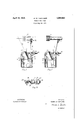
Fig. 1 is a plan view of a feeler embodying my invention with the cover of the housing removed showing in full and dotted lines two positions of the feeler member; V
Fig. 2 is a similar view showingthe'position of the feeler member when the filling has become exhausted'and Fig. 8 is a detailed view of the electric conductor and bushing and resilient contact therefor.
A feeler stand or housing 1 is mounted on a suitable stationary part of the loom. A side slipping feeler member 2 is slidably and rotatably mounted in said housing, which is shown in Figs. 1 and 2 with the cover removed. The feeler member consists of a tip 3 and stem portion 4, having a laterally ex-v tending heel 5cand a laterally extending arm 6. The housing 1 is provided with a stop 7 normally engaged by the stem portion 4 and is also provided with a stop, or bearing, 8
engaged by end 9 of the arm 6 when the feel er member is in rearward feeling position. The arm 6 is provided intermediate its ends with a curved portion 10 for retainingone end of a coil spring 11. The other end of this coil spring is fastened, as at 12, to the hous mg. j a a It will be noted that the portion 10 engaged by the spring 11 is very close to the line forming the longitudinal axis of stem portion 4. The point 12 is spaced considerably farther from the axis of the stem portion. Thus the longitudinal axis 13 of the coil spring forms an acute angle with the axis of the stem portion. This angle is shown as being less than 45 degrees. When the bobbin 14 contains a sufficient amount of filling, the filling will engage the tip 3 on the beat up of the lay and force the 5 feeler member axially of its stem portion, which is radially of the bobbin. That is, until the filling is substantially exhausted it retains the feeler member against side slipping movement and allows it to slide only. 108
' Obviously, if the angle formed by the spring slightly less than degrees the tip will slip less of whether the filling were exhausted or not. Itwill be seen from the dotted line show-1 ing of Fig; 1 that sliding of the feelerxmember serves to elongate the spring 11 and rotate it about point 12 as a pivot, thus decreasing the aforementioned angle. This angle could, therefore, prob'ab'lyb'e made equal to or; slightly greater than 45 degrees with the result that thetip '31 Would slip on a bare bobbin only after the feeler member had been caused to slide, n a right line, an. appreciable distance. However, With this angle readily upon the bare bobbin when the filling becomes substantially exhausted, and a very light spring Wlll serve to return the feel- 1 er member to its normal position.
Inthus slipping, the tip portion is rotated about the bearing point 8 and the feeler member contacts With an electric conductor 15. This conductor consists ofa threaded portion IG'extending through an insulating bushing 17 in the housing 1, and a yielding, contact portion 18'. This contact portion, in the present instance, consists of a coiled Wire spring having a closed helical portion 19 threaded on the conductor 16, and an open resilient heli cal portion 20 adapted tofyield when contacted by the feeler member.
A fibre Washer 21 is positioned on the conductor between a nut 22 and the housing 1 to complete the insulation of the conductor fromv the housing. Completion of the: .oirunit from the conductor through the feeler member operates through any of the conven 'tional means to effect a predetermined change in the operation of. the loom, such as replentip, a stem and a laterally extending arm; a spring acting on said arm obliquely to said sliding movement; an insulating bushing extending through the housing; an electrical conductor extending through said bushing; and a coiled wire spring .on the end of said conductor adapted to be contacted by said feeler stem upon substantial exhaustion of I the filling to. complete the circuit from the.
conductor to the feeler st'enn 2. An electrical feel'er for looms: comprising: afeeler stand; a side slipping feeler member thereon; an insulating bushing supported by said stand; a conductor extending through said'bushing; and a coiled spring mounted on the end of said conductor, said 7 spring being comprised of a closedhel-ix and an open helix and the. closed portion being secured on said. conductor.
3. An electrical feeler for looms comprisadapted to be actuated in a predetermined manner upon detectionof substantial. exhaus tio-n offi-lling an insulating bushing carried by said stand; a threaded conductor passing through said bushing; a coiled springonsaid conductor comprised of a=closed.heli-x, and an open resilient part in; position to be compressed by said feeler member in completing an electric circuit, said closed part being,
threaded onto said conductor.
4. An electrical feeler for loomscomprising: a feeler stand; aside slipping feeler 7 ing a feeler stand; a feeler member. thereon member mounted thereon; an insulating bushing carried by said stand; an electrical conductor extending through said bushing;
and a yielding tip on said conductor in-posr tion to be engaged and compressed by said feeler member upon slipping of the same, to complete an electric circuit and effect a preloom. v
' nAnnYw; THATGHER.
ishmentof the filling, or stopping of the 10 m so that replenishment of the filling may be accomplished manually.
Certain features of my invention may be useful Without others. Particularly it is noted that the electric contact member may ,7
be used with other types of feelers, and that the spring arrangement may be used With- 7 out an electric conductor, substituting therefor any of the usual mechanically operating means.
It is to be understood that the foregoing is merely descriptive of a preferred embodimentof my invention and may be departed from inmany of the details.
I claim as my invention:
- 1. An electrical side slipping feeler for looms comprising: a housing; a feeler member slidably and rotatably mounted in said housing, said member including a feeler determined change in the operation of the
Priority Applications (1)
| Application Number | Priority Date | Filing Date | Title |
|---|---|---|---|
| US540682A US1854963A (en) | 1931-05-28 | 1931-05-28 | Feeler for looms |
Applications Claiming Priority (1)
| Application Number | Priority Date | Filing Date | Title |
|---|---|---|---|
| US540682A US1854963A (en) | 1931-05-28 | 1931-05-28 | Feeler for looms |
Publications (1)
| Publication Number | Publication Date |
|---|---|
| US1854963A true US1854963A (en) | 1932-04-19 |
Family
ID=24156496
Family Applications (1)
| Application Number | Title | Priority Date | Filing Date |
|---|---|---|---|
| US540682A Expired - Lifetime US1854963A (en) | 1931-05-28 | 1931-05-28 | Feeler for looms |
Country Status (1)
| Country | Link |
|---|---|
| US (1) | US1854963A (en) |
Cited By (3)
| Publication number | Priority date | Publication date | Assignee | Title |
|---|---|---|---|---|
| US2808077A (en) * | 1955-08-05 | 1957-10-01 | Draper Corp | Filling feeler for looms |
| US2965030A (en) * | 1945-06-28 | 1960-12-20 | Ernest R Haberland | Self-excited chopper for mines and torpedoes |
| US3217753A (en) * | 1962-08-17 | 1965-11-16 | John B Sherrill | Filling feeler for loom bobbins |
-
1931
- 1931-05-28 US US540682A patent/US1854963A/en not_active Expired - Lifetime
Cited By (3)
| Publication number | Priority date | Publication date | Assignee | Title |
|---|---|---|---|---|
| US2965030A (en) * | 1945-06-28 | 1960-12-20 | Ernest R Haberland | Self-excited chopper for mines and torpedoes |
| US2808077A (en) * | 1955-08-05 | 1957-10-01 | Draper Corp | Filling feeler for looms |
| US3217753A (en) * | 1962-08-17 | 1965-11-16 | John B Sherrill | Filling feeler for loom bobbins |
Similar Documents
| Publication | Publication Date | Title |
|---|---|---|
| US1854963A (en) | Feeler for looms | |
| US2117304A (en) | Electric feeler mechanism for looms | |
| US2263923A (en) | Picker check for looms | |
| US1499057A (en) | Filling-feeler mechanism for looms | |
| US2085716A (en) | Filling feeler mechanism | |
| US2808077A (en) | Filling feeler for looms | |
| US1873679A (en) | Internal electrical feeler for shuttles | |
| US1515887A (en) | Weft-detecting mechanism | |
| US1790214A (en) | Weft-feeler mechanism for looms for weaving | |
| US1958463A (en) | Feeler mechanism for looms | |
| US1862762A (en) | Electric feeler mechanism for looms | |
| US1447724A (en) | Filling-feeler mechanism for looms | |
| US1220686A (en) | Weft-detecting mechanism for looms. | |
| US1990332A (en) | Filling feeler | |
| USRE22056E (en) | Picker check for looms | |
| US1926167A (en) | Electric feeler mechanism for looms | |
| US1355943A (en) | Automatic switch for cigar-lighters | |
| US1594404A (en) | Feeler mechanism for looms | |
| US2445695A (en) | Filling feeler mechanism | |
| US1817141A (en) | Electrical side slip feeler | |
| US2127182A (en) | Electric filling feeler mechanism for looms | |
| US1892334A (en) | Weft feeler for automatic looms | |
| US1912048A (en) | Mounting of detector element in shuttle for electrical weft detection | |
| US2156900A (en) | Filling feeler for looms | |
| US1832530A (en) | Weft detector for looms |