US1854960A - Automatic phonograph - Google Patents
Automatic phonograph Download PDFInfo
- Publication number
- US1854960A US1854960A US469502A US46950230A US1854960A US 1854960 A US1854960 A US 1854960A US 469502 A US469502 A US 469502A US 46950230 A US46950230 A US 46950230A US 1854960 A US1854960 A US 1854960A
- Authority
- US
- United States
- Prior art keywords
- record
- carriage
- members
- stack
- turn table
- Prior art date
- Legal status (The legal status is an assumption and is not a legal conclusion. Google has not performed a legal analysis and makes no representation as to the accuracy of the status listed.)
- Expired - Lifetime
Links
- 230000033001 locomotion Effects 0.000 description 48
- 230000007246 mechanism Effects 0.000 description 25
- QSHDDOUJBYECFT-UHFFFAOYSA-N mercury Chemical compound [Hg] QSHDDOUJBYECFT-UHFFFAOYSA-N 0.000 description 10
- 229910052753 mercury Inorganic materials 0.000 description 10
- 230000009471 action Effects 0.000 description 5
- 238000005266 casting Methods 0.000 description 2
- 230000008859 change Effects 0.000 description 2
- 230000003028 elevating effect Effects 0.000 description 2
- 230000000977 initiatory effect Effects 0.000 description 2
- 230000002452 interceptive effect Effects 0.000 description 2
- 230000010355 oscillation Effects 0.000 description 2
- 230000000284 resting effect Effects 0.000 description 2
- 101100440696 Caenorhabditis elegans cor-1 gene Proteins 0.000 description 1
- 101100083253 Caenorhabditis elegans pho-1 gene Proteins 0.000 description 1
- RUPBZQFQVRMKDG-UHFFFAOYSA-M Didecyldimethylammonium chloride Chemical compound [Cl-].CCCCCCCCCC[N+](C)(C)CCCCCCCCCC RUPBZQFQVRMKDG-UHFFFAOYSA-M 0.000 description 1
- 229940000425 combination drug Drugs 0.000 description 1
- 230000000994 depressogenic effect Effects 0.000 description 1
- 238000010586 diagram Methods 0.000 description 1
- VKYKSIONXSXAKP-UHFFFAOYSA-N hexamethylenetetramine Chemical compound C1N(C2)CN3CN1CN2C3 VKYKSIONXSXAKP-UHFFFAOYSA-N 0.000 description 1
- 239000000463 material Substances 0.000 description 1
- 230000000717 retained effect Effects 0.000 description 1
- 239000011435 rock Substances 0.000 description 1
- 210000002105 tongue Anatomy 0.000 description 1
Images

Classifications
-
- G—PHYSICS
- G11—INFORMATION STORAGE
- G11B—INFORMATION STORAGE BASED ON RELATIVE MOVEMENT BETWEEN RECORD CARRIER AND TRANSDUCER
- G11B17/00—Guiding record carriers not specifically of filamentary or web form, or of supports therefor
- G11B17/02—Details
- G11B17/04—Feeding or guiding single record carrier to or from transducer unit
Definitions
- This invention relates to an automatic phonograph of the type wherein a plurality of disc records are carriedin a storage magazine and are successively removed to a turn table for playing and, when played, are returned to said storage magazine.
- the principal object of the-invention is to provide means whereby the record-changing functions may b performed by mechanism having a small number of moving parts and adapted to be assembled in a compact unit occupying small space.
- Another object of the invention is to provide such a phonograph wherein a small or large number of records may be"placedin the machine at any one time without interfering in any way with the operation thereof.
- Another object of .the invention .is to provide improvements in 'the mechanism for per-.
- the invention resides in the novel form of apparat'us used-for placing the records in the storage magazine and removing the same therefrom, This mechanism is such that the stackv of records in the magazine may be supported in such manner'that the lowermost record isnot'distorted by.
- Another feature ofthe invention resides in a novel form of carriage niechanisnr for transporting the records to the turn table for playing.- By means of this mechanism,- the records are carried to the turn-table rather than being pushed theret oov'er a supporting surface. v
- Another feature of t e invention resides in the novel means of removing the records from the carriage mechanism when they have been delivered to the turn table.
- Another feature of the invention resides in the novel mechamsm usedfor removing a record from the turn table after playing.
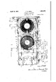
- FIG. 1 is a plan view of an automatic pho- 1 80 nograph embodying the invention with parts in the position for playing a record.
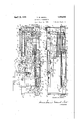
- Fig. 2 is a front elevational View of the same.
- Fig. 3 is a similar elevational view with parts removed and parts shown in section to show other parts in detail.
- Fig. 4 is afront eleva tional view of a portion of the mechanism shown in Fig. 2 with the parts thereof in the position assumed at a different point in-the' record-changing cycle.
- Fig. 5 is a perspective view of several of the parts used in plac- Fig. 6 is a perspective view showing certain parts used in the removal of a record'from the turn table.
- Fig. 7 is a plan View of the record-storage magazine and parts adjacent thereto.
- Fig. 8' is an-elevational view partly in section illustrating apparatus used for manipulation of the tone ,arm during-a change of records.
- Fig. 9 is an elevationalviewof one j of the supports for the records in the storage magazine.
- Fig.10 is a wiring diagram of electrical'connections for operat-' ing the record-changing and turn table motors;
- the frame work of the machine includes vertical frame members 10 on the four cor-1 ners thereof, a pair of upper "longitudinal Iframe m'embers ll and 11a and a pair-of.
- upper transverse frame members 12 and 12a fastened to said corner members 10'adjacent the upper ends thereof.
- a pair of lower longitudinal frame members 13 and 13a and Y a pair ofv lower transverse frame members 14 and 1411 are. connected to the corner members 10 adjacent their lower ends.
- An-electric motor 15 is bolted to the rear side of theframe and carries a driving pulhas a -downwardly-extending portion O'arrz'age moving mechanism
- the shaft 17 carries a sprocket 24 about whichis trained a sprocket chain 25 also trained about a sprocket 26 carried by a stub shaft 27.
- the stub shaft 27 is supported upon a suitable bearing carried by the frame member 11 and has fastened thereto a sprocket 28.
- a similar stub shaft 29 is also carried upon the frame member 11 and in turn carries a sprocket 30..
- a chain 31 is trained about the sprockets 28 and 30.
- a movable carriage 32 is supported by means of flanged rollers 33 .upon the frame members 11 and 11a.
- the carriage 32 34 having a slotted opening 35 therein.
- a rectangular block 36 is pivotally carried by one of the links of chain 31 and is adapted to engage the slotted opening 35.
- the roller 39 is also adapted to travel upon the frame member 11.
- the carriage 32 and bar '37 move from the position indicated in Fig. 2 a predetermined distance to the left, determined by the travel of the block 36 upon chain 31 and are then returned to the position of Fig. 2.
- certain portions of the carriage 32'and bar 37 engage and actuate certain of the record-manipulating mechanisms, as will be more fully described hereinafter.
- the mechanism for starting and stopping the motor 15 to cause thecarriage travel will also be hereinafter described in detail.
- a retaining member 43 has a semi-circular retaining portion 44 extending about one side of the stack
- the said shaft of records and has a pair of gauge portions 45 resting upon the uppermost record in the stack.
- the said gauge portions support the retaining member 43 upon the stac in such position that the upper edge of the retaining portion 44 engages the edge of the second highest record in the stack so that the highest record may be pushed from the stack over the edge of the saidretaining portion while the remainder of the records are retained in the stack.
- a link 46 is pivotally connected at one end to the retaining member 43 and at the opposite end to a vertical member 47 fastened to the frame members 11 and 13.
- link 48 is pivotally attached to the retaining member 43 at the opposite side and is pivotally attached at its opposite end to a vertical member 49 fastened to the frame members 11a and 13a.
- the retaining member 43 may be freely moved in asubstantially vertical direction but lateral movement thereof is prevented.
- the retaining member 43 may perform its function whether there is a small or large number of records in the stack.
- a record-engaging shoe 50 is provided normally resting upon the uppermost surface of the uppermost record and having 1 a portion 51 extending-downwardly and engaging the rim of the said record.
- a link 52 is pivotally attached to the said shoe and is in turn pivotally connected at its opposite end to an arm 53 in turn carried-upon a stub shaft 54.
- the link 52 is relatively long and is substantially horizontally disposed so that vertical movement of the shoe 50 is possible without material change in its lateral position.
- the shoe 50 is, therefore, adapted to rest upon the uppermost. record in the stack at substantially the same lateral position whether there is a small or large number of records in the stack.
- the stub shaft '54 is suitably supported upon the frame member 11a and carries an arm 55 in turn carrying a roller 56 upon its outer end.
- the roller 56 extends into the path of travel of a downwardly-extending portion 57 of the carriage 32.
- the downwardly-extending portion 57 ' is formed with a curved surface 58 adapted to engage the roller 56 at the proper time in the cycle-of movement of carriage 32.
- the roller 56 is elevated, thereby rocking the stub shaft 54 and arm 53 carried thereby to propel the shoe 50 to the right, referring to Fig. 3.
- the topmost record of the stack is moved upon the stack a sufiicient distance to bring the leading edge thereof beyond the retaining portion 44 :of'
- a pair of vertical rods 59 are fastened at their lower ends to oneiof the transverse supports 40 and at their upper ends to brackets carried 'by the frame members 11 and 11a.
- An elevator member 61 is associated with each of said rods and is free to slide vertically thereon.
- a pair of levers 62 are fastened at one end to a shaft 63 journaled upon the vertical members 47 and 49. Each of the levers 62 is fitted at its other end with a slotted opening 64 engaging a pin 65 upon one of the elevator members 61.
- a vertical frame member 66 is fastened to the frame members 11 and 13 and pivotally supports a bell crank 67 carrying a pin 68 adapted to engage the lower edge of one of the levers 62.
- the opposite arm of the bell criank'67 carries a roller 69 adapted to engage the lowem edge of the bar 37.
- the bar 37 travels to the left a suflicient distance to clear the roller 69 which is thus free to move upwardly.
- the weight of the elevator members 61 and the levers 62 acting upon the pin 68 rocks the bell crank 67 about its pivotal mounting, causing the roller 69 to move upwardly and permitting the elevator mem; bers 61 to be dropped to a position beside the stack of records indicated iii dotted lines in Fig. 7.
- a bevelled end portion 70 of the bar 37 engages. the roller 69, forcing the same downward.
- the movement of the ele-' vator 61 is so timed with the movement of the shoe 50 that the elevator members are first lowered, the shoe 50 is then moved to the right and retracted, bringing the uppermost record in the'stackto a position above the elevator members 61 and the elevator members are then raised to carry the record upward.
- the carriage 32 is fitted with a pair of inwardly extending record 4 supporting por tions 71, the upper surfaces of which are at a slightly higher elevation than the upper surfaces of the elevator members 61 at their highest point.
- the record-supporting members 71 are formed with bevelled'portions 72.
- the elevation of the IQCOliCl by the elevators 61 takes placed before the completion of the return movement of the carriage 32.
- the bevelled portions 72 of the members 71 engage the edge of the record and the record is lifted thereby from the elevators 61 and brought to rest upon the members 71.
- the upper surface of the record isengaged by a pair of inwardly-extending tongues 73 carried by the carriage 32so that tilting and dropping of the record is im-- possible.
- the edge of the record engages the upper end of a stationary guide member 74 fastened to the framemembers 12 and 14 so that lateral movement of the record is also impossible.
- the parts are brought to the position shown suitably supported upon a casting 77 in turn carried by the frame members 11 and 11a.
- the turn table is rotatable by means of a motor 78 in a well known manner. Adjacent the turn table 76 a transverse shaft 79 is journaled upon the frame members .11 and 11a and carries a pair of stop members 80. An arm 81 is also carried upon the shaft 79. The arm 81 extends into the path of a. block 82 carried by the bar 37; 'VVhen the carriage 32 has brought the record. into position above the turn table 76, the block 82 engages the arm 81, as illustrated in Fig.
- a transverse shaft 83 Adjacent the turn table 76, a transverse shaft 83 is journaled upon the frame members 11" and 11a and carries an L-shaped member 84 having 1ts upper end normally positioned beneath the edge of the record 85 upon the turn table.
- Theshaft 83 also carries a cam 86 extending into'the path of travel of a pin 87 carried byone of the links of the chain 31.
- the carriage 32 carries pivotally-mounted lugs 88 adapted to engage the edge of the record 85 in the movement of the carriage 32 for removing the said record from the turn table.
- the pin 87 engages the cam 86, causing the member 84 to beelevated totilt the edge of the record 85 upwardly.
- the opposite edge of the record rests upon a support member 89 carried by the casting 77 and the tilting is suflicient to free the record fromv contact with the turn table and to clear the centering pin 90 of the turn table.
- the record is engaged by the lugs 88 and is pushed from the turn table thereby.
- the record is deposited upon a tiltable apron 91 carried by a shaft 92 journaled upon the frame members 11 and 11a.
- the shaft 92 also carries an arm 93, to the outer end of whichlispivotally connected a downwardly-extending link 94.
- the link 94 is fitted at its lower end with a slotted noticed that the pm 105 does not engage the .ber 11 and universally supports a tone arm opening engaging a pin 96 carried upon a segmentally-shaped lever 97.
- the lever 97 is freely rotatable upon a shaft 98 journaled I upon the' frame members 13 and 13a.
- a link 99 is pivotally connected at one end to the lever 97 and at the opposite end'to the lower end of a lever 100.
- the lever 100 is pivotally mounted by means ofa pin 101 upon a vertical member 102 extending between the frame members 11 and 13.
- the shaft 98 fixedly carries an arm 103 and a pair .of fingers 104.
- a pin 105 is carried by the lever 97 and is adapted to engage the arm 103.
- a tension spring 106 is fastened at one end to the lever 97 and at the opposite end to the frame member 13 and serves normally to maintain the parts in the position illustrated in Fig. 2 with the apron 91 in the horizontal position illustrated in Fig. 3.
- the lever 100 is formed at its upper end with a backwardlyextending portign 107 extending into the path of travel of the pin 108 upon which the roller 39 is mounted. I v I In the travel of the carriage 32, after a a record has been placed upon the apron 91,
- the pin 108 engages the lever 100, moving the parts to the position illustrated in Fig. 4.
- the apron 91 is downwardly tilted and the record engages stop pins 109 carried thereby and is thus prevented from slipping during the tilting. It will be arm 103 until the lever 100 has been moved a predetermined distance. When this takes place, the fingers 104 are upwardly moved to engage the record 110, thus preventing the record from falling backward as the apron 91 assumes a nearly vertical position. After the apron 91 swings beyond a vertical position, the edge of the record 110 comes to rest upon a pair of'wires 111 strung between brackets 112 carried by the frame members 14 and 14a.
- a pair of transverse shafts 114 and 115 are journaled upon suitable bearings carried by frame members 13 and 13a.
- the shaft 114 carries a sprocket 116 about which is trained
- the shaft 114 also carries a pair of sprockets 119 and the shaft 115 carries a similar pair of sprockets 120.
- a pair of chains 121 are trained about the sprockets 119 and 120. The chains 117 and 121 are, therefore, moved in the direction of the arrows in Fig.
- Each of the chains 121 carries an attachment 122 adapted to engage the record when in the position 113 and to propel the record toward the stack 42.
- the chain 117 carries a pair of rollers 123 adapted to engage the lowermost record in the stack and to thereby tilt the stack to permit entrance of the record there beneath. In the movement of the chains 117 and 121, the rollers 123 travel across the face of the lowermost record in the stack and the record 113 is moved by the attachments 122 in the'wake of the rollers 123 and is thereby placed in position beneath the stack. As shown in Fig.
- the Wires 111 are fitted in grooves in the upper surface of the support members 41.
- the wires and the members 41 form a continuous support for the stack of records and this sup-port is so positioned that there is no tendency for distortion of the lowermost record by theweight of the remainder of the records in the stack.
- a bracket 124 is fastened to the frame memelectric type connected by suitable wiringto an amplifier and reproducer, not shown.
- the tone arm has fastened to the underside thereof an arcuate support member .128 extending into the path of an adjustably-positioned member 129 carried by the carriage 32.
- vertical pin 130 is guided in a suitable opening in bracket 124 and has a reduced portion 131 upon its upper end adapted to engage the lower surface of the arcuate 'member 128
- the lower end of the pin 130 is supported upon abracket 132 carried upon a lever 133.
- the lever 133 is pivotal-1y mounted by means of a pin 134 upon the frame member 11 and carries at its outer end a roller 135 adapted to ride upon the upper surface of the bar 37.
- the roller engagement with the reduced upper end 131 hand travel of the carriage 32 the 'arcuate member 128 has been mo-ved to bring a groove or recess 137 in the under surface thereof into of the pin 130.
- the tone arm is maintained in the proper position above the point for starting the playing of the record.
- the bar 37 is moved to bring the depressed portion 136 thereof again into engagement with the roller 135, permitting the tone arm to be gently lowered into recordengaging position.
- the lever143i's" formed with a shoulder ,146thereon and the upper end of said'd'ever is adapted to engage the beveled end 70 of the bar 37.
- the flexible member 142 engages, the member 141-, thus tilting the lever 139 so that the right hand end thereof reaches a higher level than the shoulder146.
- a -lever 147 is pivotally mounted upon the frame member 13 and carries a mercury switch 148.
- a spring 149 normally urges the lever 147 to the right against a stop pin 150 carried by the frame member 13.
- the upper' end of the lever 147 is in the path of travel of the bar 37 and'is engaged thereby near the completion of the travel of the carriage 32 to the left.
- the mercury switch 148V 1 is normally in the closed circuit position when the lever 147 is moved by engagement with the bar 37. Thus the switch 148 is in the open circuit position only when the carriageis near the left hand limit of its travel.
- a mercur switch 151 is carried upon the outer end of a lever 152 pivotally carried by means of a pin 153 upon the frame member '13.
- the lever 152 has an upwardly-extending portion 154'extending Into the path of travel of a slidable collar 155.
- the collar 155 is fastened to a barrel 156 having a similar collar 157 upon the opposite end thereof.
- the collars 155 and 157 and the barrel156 are slidable upon a horizontal rod 158' carried by brackets' 159 attached to the frame member 13.
- a vertical stem 160 is rotatably supported by a bracket 161 fastened to the frame member 13 and extends through the bracket 124.
- the .saidstem is fastened to the tone arm .125 and is rotatable by the said tone arm as it passes over the surface of the record.
- the stem 160 carries a' projecting arm 162 upon which is pivotally carried a d 163.
- the do 163 has a rearwardly-exten ing'p'ortion a apted to engage the collar 157 and a forwardly-extending pointed portion 164 adapted to engage the collar 155.
- the dog rides upon a stationary support member 165 fastened to the frame member 13.
- a bell crank 166 is pivotally mounted on one ofthe-brackets 159 and'ca'rries on itsvertical,
- the arm an adjustable pin 167 adapted to engage the collar 155.
- the horizontal arm of .the bell crank 166 rests u on a shoulder 168 upon the upwardly-extendlng portion 1540f lever 152.
- the said bell crank arm is formed with a shoulder 169 normally engaging the said portion of lever 152.
- the mercury switch 151 is closed circult position.
- the record being played is of the type having a spiral braking groove
- the a movement of the mercury switch 151 takes place only when the tone arm has reached the inner end of the braking groove at a point close to the center of the record.
- the record is of the type having an eccentric braking groove which oscillates the tone arm at the completion of playing of a record
- the dog 163 is oscillated with the tone arm and the outer end 164 thereof engages threads 170 on the barrel 156, thereby moving the said barrel and the collar 155 to actuate the mercury switch 151.
- the dog 163 Upon the return of the tone arm 125 to the position for the commencement of playing, the dog 163 is brought into engagement with the collar 157. The said collar, the barrel 156, and the collar 155 are thereby returned .to their initial posi- In this action, the collar 155 engages the upwardly-extending portion 154, moving the same to its initial position and permitting the bell crank 166 to drop into its initial position.
- the mercury switch 151 is moved to closed circuit position at the completion of playing of a record and is maintained in that position until the carriage 32 has moved a suflicientdistance to bring the tone arm to its initial playing position.
- a pair of wires 171 and 172 are connected to any suitable source of electric current.
- the wire 171 also leads to one terminal of the switch 148.
- the opposite terminals of the switches 173 and 148 are connected by a wire 174 with one terminal of each of the switches 151 and 140 and with one terminal of the turn table motor 78.
- the opposite terminals of each of the switches 140 and 151 are connected by a ,wire 175 with one terminal of the record-changing motor 15.
- the wire 17 2' is connected to the opposite terminals of the motors 78 and 15.
- the switches are in the position illustrated in Fig. 10 and the snap switch 173 is normally in closed circuit position.
- the switch 151 is tilted to closed circuit position, actuating the motor 15 by means of the following circuit: 171,
- a movable member adapted to travel beneath said stack.
- a support for a stack of records a retaining member adapted to be supported by the uppermost record in the stack and having a portion adapted to engage all of the records therein except the uppermost for preventing the removal thereof from the stack, and means for sliding the uppermost record from the stack.
- a supportfor a stack of records a retaining member having a retaining portion adjacent one side of said stack and havmg a gauge portion adapted to rest upon the uppermost record in the stack for supporting said member at the proper height for the upper edge of the retaining portion thereof to engage the edge "of the second highest rec:
- a siibstantially horizontally-disposed link having one end pivotally connectedto said retaining member and the opposite end pivotally connected to said frame for preventing lateral movement of said retaining member while permitting substantially vertical movement thereof, and means for sliding said uppermost record from the stack over said retaining portion.
- an automatic phonograph the combination of a support for a stack of records, a retainer adapted to prevent removal of all 1 but the uppermost of said records from the stack, an elevator, means for sliding the uppermost record of the stack to a position above said elevator, a movable carriage. mechanism for moving said elevator to lift said record to a position to be engaged by said carriage, a playing turn table, and mechanism for moving said carriage to engage said record and move the sameto said turn table.
- a retaining member having a gauge portion 7 adapted to engage the upper surface'of the uppermost record in the stack and having a retaining portion positionedto prevent removal from the stack of all but said uppermost record, an elevator positioned immediatel'y adjacent said stack, means for sliding the uppermost record upon said stack a suflicient distance to clear the gauge portion of said retaining member and to bring a portion of said record above said elevator, a movable carriage, mechanism for movin said elevator to lift said record to a 'positlon to be engaged by said'carriage, a playing turn table, and mechanism for moving said carriage to engage said record and move the same 11.
- an automatic honograph the combination of a support or a stack of records, a retaining member having a gauge portlon adapted to engage the upper surface ofothe uppermost record in'the stackand having a retaining portion positioned to prevent removal from thestack ofall but said uppermost record, an elevator having a pair of oppositely-positioned record-supporting ortionshaving arcuate inner edges ad'apte to be positioned close to said stack, means for sliding the uppermost record 11 on said stack a sufficient distance to cleart e gauge por-- tion of.
- an automatic phonograph the combination of a frame, a carriage movable upon said frame, an elevator adapted to lift a record to a predetermined level, record-sup: porting members carried by said carriage, the record-supporting surfaces thereof being slightly higher than said predetermined level and said members having bevelled portions adapted to engage a record upon said elevator in the movement of said carriage and to lift the same to rest upon said members, a stop member adapted to engage the record for preventing lateral motion thereof during said lifting, a playing turn table, means for moving said carriage to bring said record-supporting members into engagei'nent with said record and to thereafter transport said record to said turn table, and members carried by said carriage adapted to engage the upper surface of said record for steadying the same during transportation thereof;
- an automatic phonograph the com bination of a playing turn table, a movable carriage,record-supporting members carried by said carriage, record-pushing members carried by said carriage, means for moving said carriage to bring said pushing members into engagement with a record on said turn table to move said record from said turn table and to bring a second record carried by said record-supporting members into position above said turn table, stop members in the path of said records and normally freely movable from said path when engaged by the record, whereby removal of the record from the turn table is not impeded, and mechanism operable at a predetermined point in the travel of said carriage to retain said stop membersin said path to engage the record being moved to saidturn table, whereby further movement of said carriage slides said supporting members from beneath said record allowing the same to drop upon said turn table.
- a playing turn table having a rec ord-centering pin
- a movable carriage havingrecord-engaging members
- a record-tilting member adapted to engage the undersurface of a record upon said turn table at a point adjacent one edge thereof
- means for moving said carriage to bring saidrecordwith said record for removing the same from the turn, table
- a record-tilting member v adapted to engage the undersurface of a rec v 0rd upon said turn table at a point adjacent one edge thereof
- a stationary support memthe opposite edge to rest upon said stationary support member, said elevation being su ficient to remove saidrecord from contact with said turn table and to clear said centering pin for removal of the record.
- an automatic phonograph the combination of a frame, a tone arm universally mounted upon said frame, a support member carried by said tone arm, said member having a substantially horizontal undersurface, a vertical stem slidably guided upon a portion of said frame, a lever pivotally supported upon said frame and having a portion adapted to engage the lower end of said stem for supporting the same, a playing turn table, amovable carriage for moving records to said turn table for laying, an irregularly shaped member mova le with said carriage and adapted to engage said lever at a predetermined position in its travel and -to thereby lift'said lever to elevate said stem to bring the upper end thereof into engagement with the undersurface of said support member for elevating said tone arm, and means carried by said carriage for moving said tone arm and support member when so elevated, to slide said support member upon the upper end of said stem to bring said tone arm into position above the point for start of playing of a record on said turn table.
Landscapes
- Holding Or Fastening Of Disk On Rotational Shaft (AREA)
Description
April 19, 1932. T. w. SMALL 1,854,9
AUTOMAT I C PHONOGRAPH Filed July 21, 1930 s sh ets-sheet 1 I N VEN TOR. flan/rs n. JM/HA.
A TTORNEm Apr- 19; 1932. T" w SMALL 1,854,960.
AUTOMAT I C PHONOGRAPH A TTORNEYS.
April 19, 1932. T. w. sMALL AUTOMATIC PHONOGRAPH Filed July 21, 1930 s sheets-s eet s INVENTOR.
7/70/10: 14 JM/YLL {M f, g 1
. ATTORNEYJ mane; Apr. 19, 1932 UNITED STATES PATENT OFFICE THOMAS w. SHALL, F HUNTI'NGTON, INDIANA, ASSIGNOR' TO 'IHE'CAPEHABT COB- PORATION, OF FORT WAYNE, INDIANA, A CORPORATIOI N AUTOMATIC PHONOGRAPH Application filed July 21,1930. Serial li 469,502.
This invention relates to an automatic phonograph of the type wherein a plurality of disc records are carriedin a storage magazine and are successively removed to a turn table for playing and, when played, are returned to said storage magazine.
' The principal object of the-invention is to provide means whereby the record-changing functions may b performed by mechanism having a small number of moving parts and adapted to be assembled in a compact unit occupying small space.
Another object of the invention is to provide such a phonograph wherein a small or large number of records may be"placedin the machine at any one time without interfering in any way with the operation thereof.
Another object of .the invention .is to provide improvements in 'the mechanism for per-.
formin the various functions of an automatic p onogra h.
One feature 0 the invention resides in the novel form of apparat'us used-for placing the records in the storage magazine and removing the same therefrom, This mechanism is such that the stackv of records in the magazine may be supported in such manner'that the lowermost record isnot'distorted by. the
weight of the records above and issuchthat a large or small number of records may be carried in the magazine without interfering with the operation of the mechanism.
Another feature ofthe invention. resides in a novel form of carriage niechanisnr for transporting the records to the turn table for playing.- By means of this mechanism,- the records are carried to the turn-table rather than being pushed theret oov'er a supporting surface. v
Another feature of t e invention resides in the novel means of removing the records from the carriage mechanism when they have been delivered to the turn table.
Another feature of the invention resides in the novel mechamsm usedfor removing a record from the turn table after playing.
Certain features of the apparatus herein disclosed but not claimed are shown and claimed in my copending applications, Serial No. 291,221, filed July 9, 1928; Serial No.
330,379, filed January 4,.11929; Serial No. 363,776, filed May 17 1929; Serial No. 386,-
609, filed August 17, 1929 and Serial No.
443,946, filed April 14, 1930. y
Other objects and features of theinvention will be apparent from the accompanylng drawings and the following description and claims:
.Fig. 1 is a plan view of an automatic pho- 1 80 nograph embodying the invention with parts in the position for playing a record. Fig. 2 is a front elevational View of the same. Fig. 3 is a similar elevational view with parts removed and parts shown in section to show other parts in detail. Fig. 4 is afront eleva tional view of a portion of the mechanism shown in Fig. 2 with the parts thereof in the position assumed at a different point in-the' record-changing cycle. Fig. 5 is a perspective view of several of the parts used in plac- Fig. 6 is a perspective view showing certain parts used in the removal of a record'from the turn table. Fig. 7 is a plan View of the record-storage magazine and parts adjacent thereto. Fig. 8' is an-elevational view partly in section illustrating apparatus used for manipulation of the tone ,arm during-a change of records. Fig. 9 is an elevationalviewof one j of the supports for the records in the storage magazine. Fig.10 is a wiring diagram of electrical'connections for operat-' ing the record-changing and turn table motors;
' Frame j v The frame work of the machine includes vertical frame members 10 on the four cor-1 ners thereof, a pair of upper "longitudinal Iframe m'embers ll and 11a and a pair-of.
upper transverse frame members 12 and 12a fastened to said corner members 10'adjacent the upper ends thereof. A pair of lower longitudinal frame members 13 and 13a and Y a pair ofv lower transverse frame members 14 and 1411 are. connected to the corner members 10 adjacent their lower ends.
Power mechanism An-electric motor 15 is bolted to the rear side of theframe and carries a driving pulhas a -downwardly-extending portion O'arrz'age moving mechanism The shaft 17 carries a sprocket 24 about whichis trained a sprocket chain 25 also trained about a sprocket 26 carried by a stub shaft 27. The stub shaft 27 is supported upon a suitable bearing carried by the frame member 11 and has fastened thereto a sprocket 28. A similar stub shaft 29 is also carried upon the frame member 11 and in turn carries a sprocket 30.. A chain 31 is trained about the sprockets 28 and 30. Thus rotation of shaft 17 by the motor 15 causes movement of the chains 25 and 31 and this move ment is in the direction of the,arrows inFigs. 2v and 3. A movable carriage 32 is supported by means of flanged rollers 33 .upon the frame members 11 and 11a. The carriage 32 34 having a slotted opening 35 therein. A rectangular block 36 is pivotally carried by one of the links of chain 31 and is adapted to engage the slotted opening 35. By this means, continuous movement of the chain 31 in the direction of the' arrow causes reciprocating movement of the carriage 32 upon the frame members 11 and 11a. A bar 37 is fastened to the downwardly-extending portion 34 of the carriage 32 and is formed with an upwardly-extending end portion 38 having a roller 39 attached thereto. The roller 39 is also adapted to travel upon the frame member 11. In the operation of changing records, the carriage 32 and bar '37 move from the position indicated in Fig. 2 a predetermined distance to the left, determined by the travel of the block 36 upon chain 31 and are then returned to the position of Fig. 2. In this travel, certain portions of the carriage 32'and bar 37 engage and actuate certain of the record-manipulating mechanisms, as will be more fully described hereinafter. The mechanism for starting and stopping the motor 15 to cause thecarriage travel will also be hereinafter described in detail.
Mechanism for moving record from storage magazine to turn table a A. pair of transverse supports 40 are fastened to frame-members 13 and 13a and carry longitudinal supports 41 in turn carrying a stack of records 42. A retaining member 43 has a semi-circular retaining portion 44 extending about one side of the stack The said shaft of records and has a pair of gauge portions 45 resting upon the uppermost record in the stack. The said gauge portions support the retaining member 43 upon the stac in such position that the upper edge of the retaining portion 44 engages the edge of the second highest record in the stack so that the highest record may be pushed from the stack over the edge of the saidretaining portion while the remainder of the records are retained in the stack. A link 46 is pivotally connected at one end to the retaining member 43 and at the opposite end to a vertical member 47 fastened to the frame members 11 and 13. A
For removing the uppermost record from the stack, a record-engaging shoe 50 is provided normally resting upon the uppermost surface of the uppermost record and having 1 a portion 51 extending-downwardly and engaging the rim of the said record. A link 52 is pivotally attached to the said shoe and is in turn pivotally connected at its opposite end to an arm 53 in turn carried-upon a stub shaft 54. The link 52 is relatively long and is substantially horizontally disposed so that vertical movement of the shoe 50 is possible without material change in its lateral position. The shoe 50 is, therefore, adapted to rest upon the uppermost. record in the stack at substantially the same lateral position whether there is a small or large number of records in the stack. The stub shaft '54 .is suitably supported upon the frame member 11a and carries an arm 55 in turn carrying a roller 56 upon its outer end. The roller 56 extends into the path of travel of a downwardly-extending portion 57 of the carriage 32. The downwardly-extending portion 57 'is formed with a curved surface 58 adapted to engage the roller 56 at the proper time in the cycle-of movement of carriage 32.
means of this engagement, the roller 56 is elevated, thereby rocking the stub shaft 54 and arm 53 carried thereby to propel the shoe 50 to the right, referring to Fig. 3. In this movement of the shoe 50,.the topmost record of the stack is moved upon the stack a sufiicient distance to bring the leading edge thereof beyond the retaining portion 44 :of'
the retaining member 43 and to slip the said record from beneath the gauge members 45.
A pair of vertical rods 59 are fastened at their lower ends to oneiof the transverse supports 40 and at their upper ends to brackets carried 'by the frame members 11 and 11a. An elevator member 61 is associated with each of said rods and is free to slide vertically thereon. A pair of levers 62 are fastened at one end to a shaft 63 journaled upon the vertical members 47 and 49. Each of the levers 62 is fitted at its other end with a slotted opening 64 engaging a pin 65 upon one of the elevator members 61. A vertical frame member 66 is fastened to the frame members 11 and 13 and pivotally supports a bell crank 67 carrying a pin 68 adapted to engage the lower edge of one of the levers 62. The opposite arm of the bell criank'67 carries a roller 69 adapted to engage the lowem edge of the bar 37. In the movement of the carriage 32, the bar 37 travels to the left a suflicient distance to clear the roller 69 which is thus free to move upwardly. The weight of the elevator members 61 and the levers 62 acting upon the pin 68 rocks the bell crank 67 about its pivotal mounting, causing the roller 69 to move upwardly and permitting the elevator mem; bers 61 to be dropped to a position beside the stack of records indicated iii dotted lines in Fig. 7. In the return of the carriage 32, a bevelled end portion 70 of the bar 37 engages. the roller 69, forcing the same downward. and causing the elevator members 61 to be upwardly moved to the position indicated in Fig. 3. The movement of the ele-' vator 61 is so timed with the movement of the shoe 50 that the elevator members are first lowered, the shoe 50 is then moved to the right and retracted, bringing the uppermost record in the'stackto a position above the elevator members 61 and the elevator members are then raised to carry the record upward. The carriage 32 is fitted with a pair of inwardly extending record 4 supporting por tions 71, the upper surfaces of which are at a slightly higher elevation than the upper surfaces of the elevator members 61 at their highest point. The record-supporting members 71 are formed with bevelled'portions 72. The elevation of the IQCOliCl by the elevators 61 takes placed before the completion of the return movement of the carriage 32. In the continued movement of the carriage, the bevelled portions 72 of the members 71.engage the edge of the record and the record is lifted thereby from the elevators 61 and brought to rest upon the members 71. In this action, the upper surface of the record isengaged by a pair of inwardly-extending tongues 73 carried by the carriage 32so that tilting and dropping of the record is im-- possible. At the same time, the edge of the record engages the upper end of a stationary guide member 74 fastened to the framemembers 12 and 14 so that lateral movement of the record is also impossible. When the -'re-' turn movement of the carriage is complete, the parts are brought to the position shown suitably supported upon a casting 77 in turn carried by the frame members 11 and 11a. The turn table is rotatable by means of a motor 78 in a well known manner. Adjacent the turn table 76 a transverse shaft 79 is journaled upon the frame members .11 and 11a and carries a pair of stop members 80. An arm 81 is also carried upon the shaft 79. The arm 81 extends into the path of a. block 82 carried by the bar 37; 'VVhen the carriage 32 has brought the record. into position above the turn table 76, the block 82 engages the arm 81, as illustrated in Fig. 4, thus bringing the stop members 80 into an upright position into the pa h of the record. The record is thereby preve ted from further movement during further travel of the carriage 32 so that the support members 71 are slipped from beneath the record and the. record is allowed to drop upon the turn table in proper position for playing. In the return of the carriage, the support members 71 pass above the record upon the turn table.
Adjacent the turn table 76, a transverse shaft 83 is journaled upon the frame members 11" and 11a and carries an L-shaped member 84 having 1ts upper end normally positioned beneath the edge of the record 85 upon the turn table. Theshaft 83 also carries a cam 86 extending into'the path of travel of a pin 87 carried byone of the links of the chain 31. The carriage 32 carries pivotally-mounted lugs 88 adapted to engage the edge of the record 85 in the movement of the carriage 32 for removing the said record from the turn table. At the start of the movement of carriage 32 after playing of a record, the pin 87 engages the cam 86, causing the member 84 to beelevated totilt the edge of the record 85 upwardly. In this tilting movement, the opposite edge of the record rests upon a support member 89 carried by the casting 77 and the tilting is suflicient to free the record fromv contact with the turn table and to clear the centering pin 90 of the turn table. When the record has reached its tilted position, it is engaged by the lugs 88 and is pushed from the turn table thereby. At a point near the end of the left hand movement of the carriage 32, the record is deposited upon a tiltable apron 91 carried by a shaft 92 journaled upon the frame members 11 and 11a. The shaft 92 also carries an arm 93, to the outer end of whichlispivotally connected a downwardly-extending link 94. The link 94 is fitted at its lower end with a slotted noticed that the pm 105 does not engage the .ber 11 and universally supports a tone arm opening engaging a pin 96 carried upon a segmentally-shaped lever 97. The lever 97 is freely rotatable upon a shaft 98 journaled I upon the' frame members 13 and 13a. A link 99 is pivotally connected at one end to the lever 97 and at the opposite end'to the lower end of a lever 100. The lever 100 is pivotally mounted by means ofa pin 101 upon a vertical member 102 extending between the frame members 11 and 13. The shaft 98 fixedly carries an arm 103 and a pair .of fingers 104. A pin 105 is carried by the lever 97 and is adapted to engage the arm 103. A tension spring 106 is fastened at one end to the lever 97 and at the opposite end to the frame member 13 and serves normally to maintain the parts in the position illustrated in Fig. 2 with the apron 91 in the horizontal position illustrated in Fig. 3. The lever 100 is formed at its upper end with a backwardlyextending portign 107 extending into the path of travel of the pin 108 upon which the roller 39 is mounted. I v I In the travel of the carriage 32, after a a record has been placed upon the apron 91,
the pin 108 engages the lever 100, moving the parts to the position illustrated in Fig. 4. In this movement, the apron 91 is downwardly tilted and the record engages stop pins 109 carried thereby and is thus prevented from slipping during the tilting. It will be arm 103 until the lever 100 has been moved a predetermined distance. When this takes place, the fingers 104 are upwardly moved to engage the record 110, thus preventing the record from falling backward as the apron 91 assumes a nearly vertical position. After the apron 91 swings beyond a vertical position, the edge of the record 110 comes to rest upon a pair of'wires 111 strung between brackets 112 carried by the frame members 14 and 14a. As the carriage commences its return movement, the parts are returned to j the position shown in Figs. 2 and 3 by the action of spring 106- and the; record is brought to rest upon the wires '111 in the position indicated'by thenumeral 113 in Fig. 3. In this position, the face of the record which was uppermost during the playing is now lowermost so that, in the next playing of the record, the opposite face will be presented for playing.
A pair of transverse shafts 114 and 115 are journaled upon suitable bearings carried by frame members 13 and 13a. The shaft 114 carries a sprocket 116 about which is trained A a chain 117 also trained about 'a sprocket 118 carried by the shaft 17. The shaft 114 also carries a pair of sprockets 119 and the shaft 115 carries a similar pair of sprockets 120. A pair of chains 121 are trained about the sprockets 119 and 120. The chains 117 and 121 are, therefore, moved in the direction of the arrows in Fig. 3 by the rotation of the of the said sprockets and the number of links in each chain are chosen so that each-chain makes a complete revolution for each complete revolution of the chain 31. Each of the chains 121 carries an attachment 122 adapted to engage the record when in the position 113 and to propel the record toward the stack 42. The chain 117 carries a pair of rollers 123 adapted to engage the lowermost record in the stack and to thereby tilt the stack to permit entrance of the record there beneath. In the movement of the chains 117 and 121, the rollers 123 travel across the face of the lowermost record in the stack and the record 113 is moved by the attachments 122 in the'wake of the rollers 123 and is thereby placed in position beneath the stack. As shown in Fig. 9, the Wires 111 are fitted in grooves in the upper surface of the support members 41. Thus the wires and the members 41 form a continuous support for the stack of records and this sup-port is so positioned that there is no tendency for distortion of the lowermost record by theweight of the remainder of the records in the stack.
M echa-nism for tone arm manipulation A bracket 124 is fastened to the frame memelectric type connected by suitable wiringto an amplifier and reproducer, not shown. The tone arm has fastened to the underside thereof an arcuate support member .128 extending into the path of an adjustably-positioned member 129 carried by the carriage 32.
During the playing of a record, the roller engagement with the reduced upper end 131 hand travel of the carriage 32, the 'arcuate member 128 has been mo-ved to bring a groove or recess 137 in the under surface thereof into of the pin 130. By means of this engagement, the tone arm is maintained in the proper position above the point for starting the playing of the record. Upon the return of the car-- riage 32, the bar 37 is moved to bring the depressed portion 136 thereof again into engagement with the roller 135, permitting the tone arm to be gently lowered into recordengaging position.
.E'lectrz'aal connections for actuation of redcord-ohanging motor and tum table m0- tor A bracket- 138. carried by the gear housing 18 pivotally supportsalever 139 carrying a mercury switch 140. The'lever 139 carries at one endan upwardly-extending member 141adapted to engage a downwardly-extend ing flexible member 142 carried by the por- Ition 34 of carriage 32. -A lever 143 is pivotally mounted by means'of a pin 144 upon the adjacent frame member 10 and is normally urged toward the left (Fig. 2) by a tensions spring 145. The lever143i's" formed with a shoulder ,146thereon and the upper end of said'd'ever is adapted to engage the beveled end 70 of the bar 37. In-the movement of the carriage 32 to the' left, the flexible member 142 engages, the member 141-, thus tilting the lever 139 so that the right hand end thereof reaches a higher level than the shoulder146.
' Since the bar 37 has moved from its engage- 145, permitting the end oflever 139 to come to rest upon the shoulder 146. In this posiment with; the upper end of lever 143, the said lever is moved to the left by-the spring tion, the mercury switch 140 is in the closed circuitposition. Upon the. return of the'carriage 32 the bar 37'engages lever 143, moving the same to the right and permitting the lever 139 to drop to the position shown in Fig. 2, in which position the mercury switch 140 is in the open circuit position. Thus the mer- :ury switch 140 is in open circuit position only when the carriage 32 has completed its return to the initial position and for a short portion of the travel of the said carriage to the left.
A -lever 147 is pivotally mounted upon the frame member 13 and carries a mercury switch 148. A spring 149 normally urges the lever 147 to the right against a stop pin 150 carried by the frame member 13. The upper' end of the lever 147 is in the path of travel of the bar 37 and'is engaged thereby near the completion of the travel of the carriage 32 to the left. The mercury switch 148V 1 is normally in the closed circuit position when the lever 147 is moved by engagement with the bar 37. Thus the switch 148 is in the open circuit position only when the carriageis near the left hand limit of its travel.
A mercur switch 151 is carried upon the outer end of a lever 152 pivotally carried by means of a pin 153 upon the frame member '13. The lever 152 has an upwardly-extending portion 154'extending Into the path of travel of a slidable collar 155. The collar 155 is fastened to a barrel 156 having a similar collar 157 upon the opposite end thereof. The collars 155 and 157 and the barrel156 are slidable upon a horizontal rod 158' carried by brackets' 159 attached to the frame member 13. A vertical stem 160 is rotatably supported by a bracket 161 fastened to the frame member 13 and extends through the bracket 124. The .saidstem is fastened to the tone arm .125 and is rotatable by the said tone arm as it passes over the surface of the record. The stem 160 carries a' projecting arm 162 upon which is pivotally carried a d 163. The do 163 has a rearwardly-exten ing'p'ortion a apted to engage the collar 157 and a forwardly-extending pointed portion 164 adapted to engage the collar 155. The dog rides upon a stationary support member 165 fastened to the frame member 13. A bell crank 166 is pivotally mounted on one ofthe-brackets 159 and'ca'rries on itsvertical,
arm an adjustable pin 167 adapted to engage the collar 155. The horizontal arm of .the bell crank 166 rests u on a shoulder 168 upon the upwardly-extendlng portion 1540f lever 152. The said bell crank arm is formed with a shoulder 169 normally engaging the said portion of lever 152.
' In the operation of the apparatus, at the I start of playing a record, the parts are'inthe position shown in Fig. 2.' As the playing of the record progresses, the tone arm moves over the surface thereof rotating the stem 160 and moving the dog 163 to the right.- In this movement, the dog 163 is supported by the stationary support 165 preventing the forwardly-extending portion 164 from engaging the barrel 156 until it has progressed to the collar 155 or nearly to that position. Further travel 'of the tone arm upon the record causes the. dog 163 to move the co ar 155, barrel 156 and collar 157 to the right. In this action, movement of the lever. 152 is prevented by the engagement of portion 154 thereof with the shoulder 169. When the cbllar 155 is moveda suflicient distance toengagethe pin 167, the bell crank 166 is rocked tions.
thereby, lifting the horizontal arm thereof and permitting the lever 152 to drop, bringing the mercury switch 151 into closed circult position. If the record being played is of the type having a spiral braking groove, the a movement of the mercury switch 151 takes place only when the tone arm has reached the inner end of the braking groove at a point close to the center of the record. If the record is of the type having an eccentric braking groove which oscillates the tone arm at the completion of playing of a record, the dog 163 is oscillated with the tone arm and the outer end 164 thereof engages threads 170 on the barrel 156, thereby moving the said barrel and the collar 155 to actuate the mercury switch 151. Upon the return of the tone arm 125 to the position for the commencement of playing, the dog 163 is brought into engagement with the collar 157. The said collar, the barrel 156, and the collar 155 are thereby returned .to their initial posi- In this action, the collar 155 engages the upwardly-extending portion 154, moving the same to its initial position and permitting the bell crank 166 to drop into its initial position. By this mechanism, therefore, the mercury switch 151 is moved to closed circuit position at the completion of playing of a record and is maintained in that position until the carriage 32 has moved a suflicientdistance to bring the tone arm to its initial playing position.
, A pair of wires 171 and 172 (Fig. 10) are connected to any suitable source of electric current. The wire '171vleads to one terminal of a switch 173 which may be a manually-operated snap switch or a coin-controlled switch as desired. The wire 171 also leads to one terminal of the switch 148. The opposite terminals of the switches 173 and 148 are connected by a wire 174 with one terminal of each of the switches 151 and 140 and with one terminal of the turn table motor 78. The opposite terminals of each of the switches 140 and 151 are connected by a ,wire 175 with one terminal of the record-changing motor 15. The wire 17 2'is connected to the opposite terminals of the motors 78 and 15.
During the playing of a record, the switches are in the position illustrated in Fig. 10 and the snap switch 173 is normally in closed circuit position. At the completion of playing of a record, the switch 151 is tilted to closed circuit position, actuating the motor 15 by means of the following circuit: 171,
' 173 or 14s, 174,15'1,175,15,172. The travel of the carriage 32 and the movement of the remainder of the record-changing mechanism is thereby started. When the said travel has progressed a short distance, the switch 140 is tilted to closed circuit position by the engagement of members 142'and 141 and since this switch is in parallelwith switch 151, the
circuit is maintained even after switch 151 has been moved to open circuit position by the return of the tone arm to initial playing position. Upon the return of carriage 32 to initial position, mercury switch 140 is tilted to open circuit position by engagement of bar 37 with lever'143. The circuit is theresince the switch 148 also supplies the con- I nection for this motor. 7 At the completion of the left hand travel of the carriage 32, however, the switch 148 is moved to open circuit position by the engagement of bar 37 with lever 147. The circuits for both motors are thereby broken, the motors are stopped and the machine comes to rest. When the switch 173 is again moved to closed circuit position, the record-changing cycle is resumed.-
The invention claimed is:
1. In an automatic phonograph, the combination of a support for a stack of records. a member adapted to engage the undersurface of the lowermost record for tilting said stacl:
to permit entrance of a record therebeneath. and means for sliding a record beneath said stack when so tilted.
2. In an automatic phonograph. the (ombination of a support for a stack of records.
a movable member adapted to travel beneath said stack. means for moving said member to engage the undersu face of the lowermost record for tilting said stack to permit entrance of a record therebeneath and for movmentioned record. and means for sliding a record beneath said stack when so tilted.
3. In an automatic phonograph, the combination of a support for a stack of records. 1
ing said member from the path of said lastundersurfaceof the lowermost record and adapted totravel across said surface for lifting said stack, and means for sliding a record beneath said stack in the wake of the movement of said roller.
5. In an automatic phonograph, the combination of a support for a stack of records, a retaining member adapted to be supported by the uppermost record in the stack and having a portion adapted to engage all of the records therein except the uppermost for preventing the removal thereof from the stack, and means for sliding the uppermost record from the stack. 6. In an automatic phonograph, the combination of a supportfor a stack of records, a retaining member having a retaining portion adjacent one side of said stack and havmg a gauge portion adapted to rest upon the uppermost record in the stack for supporting said member at the proper height for the upper edge of the retaining portion thereof to engage the edge "of the second highest rec:
0rd in the stack, and means for sliding said uppermost record from the stack over said retaining portion.
7. In an automatic phonograph, the combination of a frame, a support for a stack of records, a retaining member having a gauge portion adapted to engage the upper surface of the uppermost record in the stack and ha ing a retaining portion positioned to prevent removal from the stack of all but said uppermost recoi'd, a substantially horizontally-dis posed link having one end pivotally connected.
to said retaining member and the opposite end pivotally connected to said frame for preventing lateralmovement of said retaining thereof to engage the edge of the second highest record in the stack. a siibstantially horizontally-disposed link having one end pivotally connectedto said retaining member and the opposite end pivotally connected to said frame for preventing lateral movement of said retaining member while permitting substantially vertical movement thereof, and means for sliding said uppermost record from the stack over said retaining portion.
9. In an automatic phonograph, the combination of a support for a stack of records, a retainer adapted to prevent removal of all 1 but the uppermost of said records from the stack, an elevator, means for sliding the uppermost record of the stack to a position above said elevator, a movable carriage. mechanism for moving said elevator to lift said record to a position to be engaged by said carriage, a playing turn table, and mechanism for moving said carriage to engage said record and move the sameto said turn table.
10. In an automatic phonograph, the combination of a support for a stackof records,
'to said turn table.
a retaining member having a gauge portion 7 adapted to engage the upper surface'of the uppermost record in the stack and having a retaining portion positionedto prevent removal from the stack of all but said uppermost record, an elevator positioned immediatel'y adjacent said stack, means for sliding the uppermost record upon said stack a suflicient distance to clear the gauge portion of said retaining member and to bring a portion of said record above said elevator, a movable carriage, mechanism for movin said elevator to lift said record to a 'positlon to be engaged by said'carriage, a playing turn table, and mechanism for moving said carriage to engage said record and move the same 11. In an automatic honograph the combination of a support or a stack of records, a retaining member having a gauge portlon adapted to engage the upper surface ofothe uppermost record in'the stackand having a retaining portion positioned to prevent removal from thestack ofall but said uppermost record, an elevator having a pair of oppositely-positioned record-supporting ortionshaving arcuate inner edges ad'apte to be positioned close to said stack, means for sliding the uppermost record 11 on said stack a sufficient distance to cleart e gauge por-- tion of. said retaining member and .to bring a portion of said record above said elevator, a movable carriage, mechanism for moyingsaid elevator to lift said rcordto a position to be engaged by said carriage, a playin turn table, and mechanism for moving sai carriage to engage said record and movethe same to-said turn table. 12. In an automatic phonograph, the combination of a frame, a carriage movable upon said frame, an elevator adapted to lift a record toa predetermined level, record-supporting members carried by said carriage,
the record-supporting surfaces thereof being slightly higher than said predetermined level and said members having bevelled portions adapted to engage a record upon said elevator in the movement of said carriage and to lift the same to rest'upon said members, astop memberadapted toengage the record for preventing lateral motion thereof during said lifting, a playing turn table, and means for moving said carriage to bring said recordsupportihg members into engagementwith said record and to thereafter transport'said record to said turn table. I 'j 13. In an automatic phonograph, the combination of a frame, a carriage movable upon said frame, an elevator adapted to lift a record to a predetermined level, record-sup: porting members carried by said carriage, the record-supporting surfaces thereof being slightly higher than said predetermined level and said members having bevelled portions adapted to engage a record upon said elevator in the movement of said carriage and to lift the same to rest upon said members, a stop member adapted to engage the record for preventing lateral motion thereof during said lifting, a playing turn table, means for moving said carriage to bring said record-supporting members into engagei'nent with said record and to thereafter transport said record to said turn table, and members carried by said carriage adapted to engage the upper surface of said record for steadying the same during transportation thereof;
14. In an automatic phonograph, the combination of a frame, a carriage movable thereon, record-supporting members carried by,
said carriage, a playing turn table, means for moving said carriageto bring a record carried thereby to a pgsition above said turn table, stop members adapted to engage said record when said position has been reached to prevent further movement thereof, whereby.,further movement of said carriage slides said supporting members from beneath said record allowing the same to drop upon said turn table, members carried by said carriage for pushing said record from the turn table upon the next succeeding movement of said carriage, andmeans for retaining said stop members in record-stopping position when a record is moved. to the turntable, said means being inoperative when a record is removed,
from the turn table.
15. In an automatic phonograph, the com bination of a playing turn table, a movable carriage,record-supporting members carried by said carriage, record-pushing members carried by said carriage, means for moving said carriage to bring said pushing members into engagement with a record on said turn table to move said record from said turn table and to bring a second record carried by said record-supporting members into position above said turn table, stop members in the path of said records and normally freely movable from said path when engaged by the record, whereby removal of the record from the turn table is not impeded, and mechanism operable at a predetermined point in the travel of said carriage to retain said stop membersin said path to engage the record being moved to saidturn table, whereby further movement of said carriage slides said supporting members from beneath said record allowing the same to drop upon said turn table.
16. In an automatic phonograph, the combination of a playing turn table, a movable carriage, record-supporting members carried by said carriage, record-pushing members carried by said carriage, means for moving said carriage to bring said pushing members into engagement with a record on said turn table to move said record from said turn table and to bring a second record carried by said record-supporting members into position above said turn table, and stop members movable from the path of said records during the removal of a record from the turn table and movable into the path of said records to ensaid carriage to bring said pushing members into engagement with a record on said turn table to move said record form said turn table and to bring a second record carried by said record-supporting members into position above said turn table, stop members inthe path of said records and normally freely movable from said path whenengaged by the record, whereby removal of the record from the turn table is not impeded, an operating arm connected to said stop members, and a member carried by said carriage and engageable with said operating arm at a predetermined point in the travel of said" carriage to retain said stop members in position to engage the. record being moved to the turn table, whereby further movement of said carriage slides said supporting members from beneath said record allowing the same to drop .upon' said turn table.
18. In an automatic phonograph, the combination of a playing turn table having a rec ord-centering pin, a movable carriage havingrecord-engaging members, a record-tilting member adapted to engage the undersurface of a record upon said turn table at a point adjacent one edge thereof, means for moving said carriage to bring saidrecordwith said record for removing the same from the turn, table, a record-tilting member v adapted to engage the undersurface of a rec v 0rd upon said turn table at a point adjacent one edge thereof, a stationary support memthe opposite edge to rest upon said stationary support member, said elevation being su ficient to remove saidrecord from contact with said turn table and to clear said centering pin for removal of the record.
20. In an automatic phonograph, the combination of a frame, a tone arm universally mounted upon said frame, a support member carried by said tone arm, said member having a substantially horizontal undersurface, a vertical stem slidably guided upon a portion of said frame, a lever pivotally supported upon said frame and having a portion adapted to engage the lower end of said stem for supporting the same, a playing turn table, amovable carriage for moving records to said turn table for laying, an irregularly shaped member mova le with said carriage and adapted to engage said lever at a predetermined position in its travel and -to thereby lift'said lever to elevate said stem to bring the upper end thereof into engagement with the undersurface of said support member for elevating said tone arm, and means carried by said carriage for moving said tone arm and support member when so elevated, to slide said support member upon the upper end of said stem to bring said tone arm into position above the point for start of playing of a record on said turn table.
21. In an automatic phonograph, the combination of a frame, a tone arm universally mounted upon said frame, a support member fastened to said tone arm, said member having a substantially horizontal undersurface having a recess therein, a vertical stem slidably guided upon a portion of said frame, a lever pivotally supported upon said frame and having a portion adapted to engage the lower end of said stem for supporting the same, a playing turn table, a movable carriage for moving records to said turn table for playing, an irregularly-shaped member movable with said carriage and adapted to engage said lever at a predetermined position in its travel and to thereby lift said lever to elevate said stem to bring the upper end thereof into engagement with the undersurface of said support member for elevating said tone arm, and an element-carried by said carriage adapted to move said tone arm and support member when so elevated to slide said support member upon the upper end of said stem to bring said recess into engagement with the upper end of said stem, the parts being so proportioned that said engagement takes place when the tone arm has reached a position above the point for start of playingof a record on said turn table.
22. In an automatic phonograph, the combination of a tone arm, a dog, means operatively connecting said dog and tone arm for movement of said dog by the movement of said tone arm in the playing of a record, electrically operated record changing and tone arm returning mechanism, a switch device for initiating the actuation of said mechanism, an axially slidable barrel adapted to engage and actuate said switch device, said barrel having a collar at each end, one of said collars being engageable by said dog for moving said barrel to engage and actuate said switch device and the other of said collars being engageable by said dog for returning said barrel to initial position upon the return of said tone arm'to initial position, said collars being spaced apart a greater distance than the length of said dog so that a predetermined initial movement of said tone arm in either direction is required before movement of said barrel takes place, threads formed on said barrel between said collars and engageable by said dog for moving said barrel to actuate said switch device, and means for preventing engagement of said dog and threads during the initial art of the tone arm travel in the playing 0 a record, whereby said engagement can only be made by oscillation of the tone arm and dog during the final part of said travel.
23. In an automatic phonograph, the combination of a tone arm, a dog, means operatively connecting said dog and tone arm for movement of said dog by the movement of said tone arm in the playing of a record, rec- 0rd changing and tone arm returning mechanism, a device for initiating the action of 1 said mechanism, a movable member adapted to engage and actuate said device, said member having a portion engageable by said dog for movement thereof for actuating said device and another portion engageable for returning said member to initial position upon the return of said tone arm to initial position, said portions being so spaced that a predetermined initial movement of the tone arm in either direction is required before engagement thereof, another portion formed on said movable member engageable by said dog for moving said member to actuate said device, and means for preventing, said last mentioned engagement during the initial part of the tone arm travel in the playing of a record, whereby said engagement can only be made by oscillation of said tone arm and dog during the final part of said travel.
In witness whereof, I have hereunto affixed my signature. v THOMAS W. SMALL.
Priority Applications (1)
| Application Number | Priority Date | Filing Date | Title |
|---|---|---|---|
| US469502A US1854960A (en) | 1930-07-21 | 1930-07-21 | Automatic phonograph |
Applications Claiming Priority (1)
| Application Number | Priority Date | Filing Date | Title |
|---|---|---|---|
| US469502A US1854960A (en) | 1930-07-21 | 1930-07-21 | Automatic phonograph |
Publications (1)
| Publication Number | Publication Date |
|---|---|
| US1854960A true US1854960A (en) | 1932-04-19 |
Family
ID=23864034
Family Applications (1)
| Application Number | Title | Priority Date | Filing Date |
|---|---|---|---|
| US469502A Expired - Lifetime US1854960A (en) | 1930-07-21 | 1930-07-21 | Automatic phonograph |
Country Status (1)
| Country | Link |
|---|---|
| US (1) | US1854960A (en) |
-
1930
- 1930-07-21 US US469502A patent/US1854960A/en not_active Expired - Lifetime
Similar Documents
| Publication | Publication Date | Title |
|---|---|---|
| US3756608A (en) | Automatic cassette changer | |
| US1854960A (en) | Automatic phonograph | |
| US2056372A (en) | Control for phonographs | |
| US2047749A (en) | Automatic record changing phonograph | |
| US2002236A (en) | Automatic phonograph | |
| US1918588A (en) | Automatic sound reproducing apparatus | |
| US2896953A (en) | Tone arm mounting for gramophones | |
| US1872835A (en) | Automatic phonograph | |
| US2881264A (en) | Dictation equipment | |
| US1590654A (en) | Automatic phonograph | |
| US2018881A (en) | Automatic phonograph | |
| US3953036A (en) | Method of and apparatus for reproducing recorded information | |
| US1958801A (en) | Automatic phonograph record changing means and method | |
| US5036414A (en) | Magnetic tape cassette apparatus having loading/unloading mechanism with spring-biased components | |
| US2978249A (en) | Accessory for automatic record changer | |
| US1993073A (en) | Phonograph | |
| US2645496A (en) | Automatic phonograph mechanism | |
| US1977456A (en) | Automatic graphophone | |
| US1818645A (en) | Automatic disk record player | |
| US2109322A (en) | Automatic record changing phonograph | |
| US1460940A (en) | Automatic replay and record shift for phonographs | |
| US1991964A (en) | Automatic record changing phonograph | |
| US2875623A (en) | Multi-speed phonograph drive | |
| US1979276A (en) | Automatic gramophone | |
| US928567A (en) | Sound-reproducing machine. |