US1854957A - Welding machine - Google Patents
Welding machine Download PDFInfo
- Publication number
- US1854957A US1854957A US460986A US46098630A US1854957A US 1854957 A US1854957 A US 1854957A US 460986 A US460986 A US 460986A US 46098630 A US46098630 A US 46098630A US 1854957 A US1854957 A US 1854957A
- Authority
- US
- United States
- Prior art keywords
- edges
- welding
- mandrel
- sheet
- channels
- Prior art date
- Legal status (The legal status is an assumption and is not a legal conclusion. Google has not performed a legal analysis and makes no representation as to the accuracy of the status listed.)
- Expired - Lifetime
Links
- 238000003466 welding Methods 0.000 title description 36
- 239000002184 metal Substances 0.000 description 17
- 238000010276 construction Methods 0.000 description 1
- 238000005728 strengthening Methods 0.000 description 1
Images

Classifications
-
- B—PERFORMING OPERATIONS; TRANSPORTING
- B23—MACHINE TOOLS; METAL-WORKING NOT OTHERWISE PROVIDED FOR
- B23K—SOLDERING OR UNSOLDERING; WELDING; CLADDING OR PLATING BY SOLDERING OR WELDING; CUTTING BY APPLYING HEAT LOCALLY, e.g. FLAME CUTTING; WORKING BY LASER BEAM
- B23K11/00—Resistance welding; Severing by resistance heating
- B23K11/06—Resistance welding; Severing by resistance heating using roller electrodes
- B23K11/061—Resistance welding; Severing by resistance heating using roller electrodes for welding rectilinear seams
- B23K11/062—Resistance welding; Severing by resistance heating using roller electrodes for welding rectilinear seams for welding longitudinal seams of tubes
- B23K11/063—Lap welding
Definitions
- This invention relates to seam weldingmachines and the object of the invention is to provide a welding machine particularly adapted for producing tubes 1n continuous lengths from the metal sheets or strlps.
- Another object of the invention is to provide an arrangement whereby a metal sheet may be rolled to convolute form to bring the edges in spaced relation one above the other and as the edges pass" into the welder they are brought together into over-lapped relation and welded while in this relation.
- Another object of the invention is to 'provide a mandrel along'which the sheet may be fed "in convolute form and so arranged as to maintain the edges of the sheet spaced apart in over-lapping relation until fed into the welding rollers.
- a further object of the invention is to provide a longitudinal .supportcharmeled to receive the edges of a metal sheet when rolled to convolute form and arranged so that the over-lapping edges of the sheet may be fed into alap welder as the sheet passes from the supporting member.
- Another ob ect of the invention is to provide a mandrel carrying a welding roller over which the lapped edges of the, sheet may be fed, a second welding roller being provided riding on the outer surface of the lapped edges and adapted to form a lamp weld as the lapped seam passes therebeneath, i
- FIG. 1 is a front elevation of a continuous seam welding machine embodying my invention.
- Fig. 2 is an end view of the machine taken from the right end of Fig, 1. r
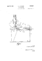
- Fig. 3 is an enlarged section taken on line 3 s of Fig. 1.
- the device com- .pr-ises a metal base member 1 having a foot 2 extending longitudinally thereof and provided with strengthening ribs 3 on the rear 0 side.
- the member 1 is provided with an in- 1930.
- This flange 4 is provided with a channel 5 on the under side and a metal supporting member 6 extends longitudinally of the channel 5 and is secured. therein by any suitable means.
- the supporting member 6 is shown more in detail in Fig,
- the mandrel 10 comprises a cylindrical barextending longitudinally of the base 1 and having a channel 11 cut therein to receive the portion 9 of the supporting mem ber 6. This portion 9 may be secured in the mandrel 10 in any desired manner such .as by machine screws 12 connecting the two members at intervals throughout their length. With the mandrel 10 secured to the member 9, as shown, a channel 13 is formed ing member 6 and a welding roller 16 is rotatably mounted in the mandrel adjacent the ends of the channels 7 and 13.
- the mandrel is also provided with a portion 17 ex tending beyond the roller 16 which forms a guide for the tubing after passing through the welding rollers.
- the welding machine'with which this device is to be used may be of'any standard make and the particular form of welding machine is unimportant except that "it have a welding roller, such as the roller'18, operating in electrical circuit with the welding roller 16. In welding machines of this type, the machine is usually adjustable. to move the roller 18 toward or away from the stationary roller 16 in order to make a proper contact for alap weld. V,
- a strip of sheet metal of desired length is rolled or positioned by hand in convolute form as shown at 19 in Fig. 3. .
- One edge of the sheet is fed into the channel 7 while the other edge isfed into the channel 13 and shoes 20 and 21 are secured to the sides of the member 6 in alignment with the upper edges of the channels 13 and 7 respectively to aid in feeding the edges of the convolute sheet into the respective channels and to prevent the edges of the sheet from coming out of the channels.
- the edges of the metal sheet are in over-lapping spaced relation and the sheet is fed lengthwise of the member 6 in this form until it passes out of the ends of these channels at the point 15.
- the device is very simple and eflicient in operation, will produce welded tubing continuously in any desired lengths, may be easily operated and provides a device which accomplishes the objects described.
- a base In a continuous seam'welding machine, a base, a depending supporting member secured to and extending longitudinally of said base, a mandrel secured to the lower edge-of the supporting member, the supporting mem her being formed to provide a pair of channels opening on opposite sidesthereof and extending longitudinally of the supporting member in spaced relation one above the other, said channels being adapted to receive and sup ort the edges of a metal sheet rooled to convo ute form in spaced overlapping relation, the edges of the metal sheet passing fr om the channels in spaced over-lapped relation, a welding roller supported in the mandrel adjacent the ends of the channels, the
- said mandrel having a portion extending beyond the discharge side of the roller, the lower edge of the metal sheet being adapted to ride on the said welding roller, a second welding roller supported above the first welding roller and adapted to contact the upper edge of the metal sheet, the said welding rollers being arranged to press the over-lapping edges of the sheet together and means for passing a welding current through the welding rollers.
- a base In a continuous seam welding machine, a base, a depending supporting member secured to and extending longitudinally of said base, a mandrel secured to the lower edge of the supporting member, the supportin memher being formed to provide a pair 0 chaning rollers adapted to bring the overlapped edges of the metal sheet to contact, means for welding the edges together as they are brought to contact, and means for supporting the welded article as it passes from the welding rollers.
- a base In a continuous seam welding machine, a base, a depending supporting member secured to and extending longitudinally of said base, a cylindrical mandrel secured to the lower edge of the supporting member and forming in combination with the supporting member a longitudinal channel opening on one side of the supporting member, the supporting member being provided with a longitudinal channel opening on the opposite side thereof from the aforementioned channel and positioned thereabove, the channels being adapted to receive the edges of a metal sheet rolled to convolute form, means for bringing the edges of the convolute sheet to contact as they pass from the channels and means for continuously welding the edges of the metal sheet together as-they are brought to contact, a mandrel having a portion extending beyond the said means for bringing the edges of the sheet to contact and providing a support for the welded article.
- a base having a horizontally extending upper edge, a depending supporting member secured in and extending longitudinally of said horizontal edge, a mandrel secured to and supported by the supporting member, the supporting. member and mandrel being formed to provide spaced channels extending longitudinally thereof in over-lapping rela tion and arranged to receive the edges of a.
- a vertical base member having a horizontally extending upper edge, a depending supporting member secured in and extending longitudinally of said horizontal edge, a mandrel 5 supported thereby, the supporting member being formed to provide spaced channels in over-lapping-relation and arranged to receive the edges of ,a metal sheet rolled to convolute form, a pair of. welding'rollers adjacent the 10 ends of the channels adapted to bring the over-lappin edges into contact, said mandrel being forme to support one of the said rollers at a distance from the discharge end and means for welding the over-lapping edges of 15 the sheet together while held in contact, the portion of the mandrel extending beyond the roller supported thereby providing a support for the welded.
- a base In a continuous seam welding machine, a base, a depending supporting member secured to and extending longitudinally of said base and formed to provide a pair of channelsextending longitudinally thereof one above the other and opening on opposite sides of the supporting member, the said channels being arranged to receive the edges of a metal sheet rolled to convolut e form, a horizontally extending shoe at the upper edge of the edge of the channels and providing a means for retaining the edges of the sheet in place, means for bringing the edges of the sheet to contact as they pass from the channels and means for welding the edges together while held in contact. 2
Landscapes
- Engineering & Computer Science (AREA)
- Mechanical Engineering (AREA)
- Lining Or Joining Of Plastics Or The Like (AREA)
Description
Apr-ii 19, 1932. c c, RD 1,854,957
WELDING MACHINE Filed June 13, 1930 2 Sheets-Sheet 2 iNvENToR ATTORNEY Patented Apr. 19, 1932 UNITED "STATES PATENT OFFICE CLEMENT C. RICHARD, OF DETROIT, MIOHIGAN, ASSIGNOR TO ALLIED PRODUCTS COR- I PORATION, OI DETROIT, MICHIGAN, A. CORPORATION OF ILLINOIS WELDING MACHINE Application filed June v13,
This invention relates to seam weldingmachines and the object of the invention is to provide a welding machine particularly adapted for producing tubes 1n continuous lengths from the metal sheets or strlps.
Another object of the invention is to provide an arrangement whereby a metal sheet may be rolled to convolute form to bring the edges in spaced relation one above the other and as the edges pass" into the welder they are brought together into over-lapped relation and welded while in this relation.
Another object of the invention is to 'provide a mandrel along'which the sheet may be fed "in convolute form and so arranged as to maintain the edges of the sheet spaced apart in over-lapping relation until fed into the welding rollers.
A further object of the invention is to provide a longitudinal .supportcharmeled to receive the edges of a metal sheet when rolled to convolute form and arranged so that the over-lapping edges of the sheet may be fed into alap welder as the sheet passes from the supporting member.
Another ob ect of the invention is to provide a mandrel carrying a welding roller over which the lapped edges of the, sheet may be fed, a second welding roller being provided riding on the outer surface of the lapped edges and adapted to form a lamp weld as the lapped seam passes therebeneath, i
v These objects and the several novel features of the invention are hereinafter more fully described and claimed and the preferred form of construction by which these objects are attained is shown in the accompanying drawings in which- Fig. 1 is a front elevation of a continuous seam welding machine embodying my invention.
Fig. 2 is an end view of the machine taken from the right end of Fig, 1. r
Fig. 3 is an enlarged section taken on line 3 s of Fig. 1.
As shown in Figs. 1 and 2 the device com- .pr-ises a metal base member 1 having a foot 2 extending longitudinally thereof and provided with strengthening ribs 3 on the rear 0 side. The member 1 is provided with an in- 1930. Serial No. 460,886.
turned flange 4 at the upper end which extends longitudinally thereof. This flange 4 is provided with a channel 5 on the under side and a metal supporting member 6 extends longitudinally of the channel 5 and is secured. therein by any suitable means. The supporting member 6 is shown more in detail in Fig,
3 and is provided with a horizontal slot 7 ex-- tending longitudinally thereof and the memher 6 is provided with a ortion 8 extending downwardly on a curve rom the slot 7 and-- providing a segmental portion 9 to which the mandrel 10 may be secured.
The mandrel 10 comprises a cylindrical barextending longitudinally of the base 1 and having a channel 11 cut therein to receive the portion 9 of the supporting mem ber 6. This portion 9 may be secured in the mandrel 10 in any desired manner such .as by machine screws 12 connecting the two members at intervals throughout their length. With the mandrel 10 secured to the member 9, as shown, a channel 13 is formed ing member 6 and a welding roller 16 is rotatably mounted in the mandrel adjacent the ends of the channels 7 and 13. The mandrel is also provided with a portion 17 ex tending beyond the roller 16 which forms a guide for the tubing after passing through the welding rollers.- The welding machine'with which this device is to be used may be of'any standard make and the particular form of welding machine is unimportant except that "it have a welding roller, such as the roller'18, operating in electrical circuit with the welding roller 16. In welding machines of this type, the machine is usually adjustable. to move the roller 18 toward or away from the stationary roller 16 in order to make a proper contact for alap weld. V,
In operation a strip of sheet metal of desired length is rolled or positioned by hand in convolute form as shown at 19 in Fig. 3. .One edge of the sheet is fed into the channel 7 while the other edge isfed into the channel 13 and shoes 20 and 21 are secured to the sides of the member 6 in alignment with the upper edges of the channels 13 and 7 respectively to aid in feeding the edges of the convolute sheet into the respective channels and to prevent the edges of the sheet from coming out of the channels. It will be noted that when positioned in the channels 7 and 13 the edges of the metal sheet are in over-lapping spaced relation and the sheet is fed lengthwise of the member 6 in this form until it passes out of the ends of these channels at the point 15. At this time, these overlapping edges of the sheet are fed between the rollers 18 and 16 which press the edges of the sheet together and hold them together during the welding operation, the" portion 17 of the mandrel acting as a guide to maintain the tube in proper alignment with the welding rollers. By means of this device, tubing of any length may be produced depending on the length of the metal sheet or strip it is possibleto obtain.
While I have described the device for use with electric welding machines, it may be used with any type of welder capable of forming a la weld.
From the oregoing description it becomes evident that the device is very simple and eflicient in operation, will produce welded tubing continuously in any desired lengths, may be easily operated and provides a device which accomplishes the objects described.
Having thus fully described'my invention, its utility and mode of operation, what I claim and desire to secure by Letters Patent of the United States isi 1. In a continuous seam'welding machine, a base, a depending supporting member secured to and extending longitudinally of said base, a mandrel secured to the lower edge-of the supporting member, the supporting mem her being formed to provide a pair of channels opening on opposite sidesthereof and extending longitudinally of the supporting member in spaced relation one above the other, said channels being adapted to receive and sup ort the edges of a metal sheet rooled to convo ute form in spaced overlapping relation, the edges of the metal sheet passing fr om the channels in spaced over-lapped relation, a welding roller supported in the mandrel adjacent the ends of the channels, the
said mandrel having a portion extending beyond the discharge side of the roller, the lower edge of the metal sheet being adapted to ride on the said welding roller, a second welding roller supported above the first welding roller and adapted to contact the upper edge of the metal sheet, the said welding rollers being arranged to press the over-lapping edges of the sheet together and means for passing a welding current through the welding rollers.
2. In a continuous seam welding machine, a base, a depending supporting member secured to and extending longitudinally of said base, a mandrel secured to the lower edge of the supporting member, the supportin memher being formed to provide a pair 0 chaning rollers adapted to bring the overlapped edges of the metal sheet to contact, means for welding the edges together as they are brought to contact, and means for supporting the welded article as it passes from the welding rollers.
3. In a continuous seam welding machine, a base, a depending supporting member secured to and extending longitudinally of said base, a cylindrical mandrel secured to the lower edge of the supporting member and forming in combination with the supporting member a longitudinal channel opening on one side of the supporting member, the supporting member being provided with a longitudinal channel opening on the opposite side thereof from the aforementioned channel and positioned thereabove, the channels being adapted to receive the edges of a metal sheet rolled to convolute form, means for bringing the edges of the convolute sheet to contact as they pass from the channels and means for continuously welding the edges of the metal sheet together as-they are brought to contact, a mandrel having a portion extending beyond the said means for bringing the edges of the sheet to contact and providing a support for the welded article.
4. In a continuous seam welding machine. a base having a horizontally extending upper edge, a depending supporting member secured in and extending longitudinally of said horizontal edge, a mandrel secured to and supported by the supporting member, the supporting. member and mandrel being formed to provide spaced channels extending longitudinally thereof in over-lapping rela tion and arranged to receive the edges of a.
a vertical base member having a horizontally extending upper edge, a depending supporting member secured in and extending longitudinally of said horizontal edge, a mandrel 5 supported thereby, the supporting member being formed to provide spaced channels in over-lapping-relation and arranged to receive the edges of ,a metal sheet rolled to convolute form, a pair of. welding'rollers adjacent the 10 ends of the channels adapted to bring the over-lappin edges into contact, said mandrel being forme to support one of the said rollers at a distance from the discharge end and means for welding the over-lapping edges of 15 the sheet together while held in contact, the portion of the mandrel extending beyond the roller supported thereby providing a support for the welded. tube as it passes from the weld- I ing rollers. a0 '6. In a continuous seam welding machine, a base, a depending supporting member secured to and extending longitudinally of said base and formed to provide a pair of channelsextending longitudinally thereof one above the other and opening on opposite sides of the supporting member, the said channels being arranged to receive the edges of a metal sheet rolled to convolut e form, a horizontally extending shoe at the upper edge of the edge of the channels and providing a means for retaining the edges of the sheet in place, means for bringing the edges of the sheet to contact as they pass from the channels and means for welding the edges together while held in contact. 2
7 In a machine for forming a continuous weld, .a vertical base member having the terminal horizontally extending upper-end at one end, a mandrel supported thereby formed with horizontal overlapping channel like por-- tions at opposite edges to receive the opposededges to be welded, said mandrel having a portion extending beyond the channel portion thereof, a roller. supported in said portion at the end of the channels, a second roller positioned thereabove, and means for supplying electric current to the rollers whereby the edges are welded together asthey pass fromthe channel, the portion of the mandrel supporting the said roller extending beyond the discharge side thereof andhaving an upper face practically in horizontal alignment with the upper part of the roller surface providing a support for the welded article as it asses from the rollers.
In testimony whereof I sign this specification.
CLEMENT C. RICHARD,
Priority Applications (1)
| Application Number | Priority Date | Filing Date | Title |
|---|---|---|---|
| US460986A US1854957A (en) | 1930-06-13 | 1930-06-13 | Welding machine |
Applications Claiming Priority (1)
| Application Number | Priority Date | Filing Date | Title |
|---|---|---|---|
| US460986A US1854957A (en) | 1930-06-13 | 1930-06-13 | Welding machine |
Publications (1)
| Publication Number | Publication Date |
|---|---|
| US1854957A true US1854957A (en) | 1932-04-19 |
Family
ID=23830802
Family Applications (1)
| Application Number | Title | Priority Date | Filing Date |
|---|---|---|---|
| US460986A Expired - Lifetime US1854957A (en) | 1930-06-13 | 1930-06-13 | Welding machine |
Country Status (1)
| Country | Link |
|---|---|
| US (1) | US1854957A (en) |
Cited By (4)
| Publication number | Priority date | Publication date | Assignee | Title |
|---|---|---|---|---|
| US2549173A (en) * | 1947-03-01 | 1951-04-17 | Nat Electric Welding Machines | Seam welding of cylindrical articles |
| US2578832A (en) * | 1945-11-05 | 1951-12-18 | Continental Can Co | Can body welding machine, including movable and rotatable electrode |
| US2666833A (en) * | 1952-06-24 | 1954-01-19 | Fansteel Metallurgical Corp | Tantalum welding fixture |
| US2886691A (en) * | 1958-08-11 | 1959-05-12 | Magnetic Heating Corp | Lapped welding of metal edge portions |
-
1930
- 1930-06-13 US US460986A patent/US1854957A/en not_active Expired - Lifetime
Cited By (4)
| Publication number | Priority date | Publication date | Assignee | Title |
|---|---|---|---|---|
| US2578832A (en) * | 1945-11-05 | 1951-12-18 | Continental Can Co | Can body welding machine, including movable and rotatable electrode |
| US2549173A (en) * | 1947-03-01 | 1951-04-17 | Nat Electric Welding Machines | Seam welding of cylindrical articles |
| US2666833A (en) * | 1952-06-24 | 1954-01-19 | Fansteel Metallurgical Corp | Tantalum welding fixture |
| US2886691A (en) * | 1958-08-11 | 1959-05-12 | Magnetic Heating Corp | Lapped welding of metal edge portions |
Similar Documents
| Publication | Publication Date | Title |
|---|---|---|
| US2649888A (en) | Mechanism for corrugating strips of material | |
| US1854957A (en) | Welding machine | |
| US3285490A (en) | Apparatus for making tubular members | |
| US2084889A (en) | Apparatus for welding | |
| US1793280A (en) | Sheet-metal pipe | |
| US2673276A (en) | Post heating of electrically welded tubes in line of production | |
| US1929415A (en) | Manufacture of welded spiral pipe | |
| US3263053A (en) | Tube forming apparatus | |
| US1661970A (en) | Electbic welding machine | |
| US611222A (en) | Method of and means for manufacturing metal tubing | |
| US1793281A (en) | Spiral-pipe-forming machine | |
| US2010155A (en) | Apparatus for welding drums | |
| US1850176A (en) | Method of and apparatus for electric resistance welding | |
| US1712507A (en) | Welding pipes | |
| US1583212A (en) | Lap-welded pipe | |
| US686558A (en) | Apparatus for manufacturing tubes, pipes, & c. | |
| US1732383A (en) | Method of and apparatus for eliectbic | |
| US1812409A (en) | Method and apparatus for preventing adherence of molten metal | |
| US1865530A (en) | Method of lap welding | |
| US2092003A (en) | Alternating current welding apparatus | |
| US1523927A (en) | Process and apparatus for making spiral tubing by electric welding | |
| US1304594A (en) | Electric seam-welding device | |
| US1654563A (en) | Electrical welding machine | |
| US444928A (en) | Method of electric welding | |
| US2714864A (en) | Mechanism for forming a helically wound tube |