US185494A - Improvement in hose-couplings - Google Patents
Improvement in hose-couplings Download PDFInfo
- Publication number
- US185494A US185494A US185494DA US185494A US 185494 A US185494 A US 185494A US 185494D A US185494D A US 185494DA US 185494 A US185494 A US 185494A
- Authority
- US
- United States
- Prior art keywords
- coupling
- hose
- couplings
- improvement
- parts
- Prior art date
- Legal status (The legal status is an assumption and is not a legal conclusion. Google has not performed a legal analysis and makes no representation as to the accuracy of the status listed.)
- Expired - Lifetime
Links
- 238000010168 coupling process Methods 0.000 title description 20
- 238000005859 coupling reaction Methods 0.000 title description 20
- 230000008878 coupling Effects 0.000 description 17
- 238000010276 construction Methods 0.000 description 1
- 238000012856 packing Methods 0.000 description 1
Images
Classifications
-
- F—MECHANICAL ENGINEERING; LIGHTING; HEATING; WEAPONS; BLASTING
- F16—ENGINEERING ELEMENTS AND UNITS; GENERAL MEASURES FOR PRODUCING AND MAINTAINING EFFECTIVE FUNCTIONING OF MACHINES OR INSTALLATIONS; THERMAL INSULATION IN GENERAL
- F16L—PIPES; JOINTS OR FITTINGS FOR PIPES; SUPPORTS FOR PIPES, CABLES OR PROTECTIVE TUBING; MEANS FOR THERMAL INSULATION IN GENERAL
- F16L37/00—Couplings of the quick-acting type
- F16L37/24—Couplings of the quick-acting type in which the connection is made by inserting one member axially into the other and rotating it to a limited extent, e.g. with bayonet-action
- F16L37/244—Couplings of the quick-acting type in which the connection is made by inserting one member axially into the other and rotating it to a limited extent, e.g. with bayonet-action the coupling being co-axial with the pipe
- F16L37/252—Couplings of the quick-acting type in which the connection is made by inserting one member axially into the other and rotating it to a limited extent, e.g. with bayonet-action the coupling being co-axial with the pipe the male part having lugs on its periphery penetrating into the corresponding slots provided in the female part
Definitions
- the object of my invention is to produce a simple and efficient device for coupling hose; and the invention consists in providing each half of a coupling with two projecting catches and two slots or openings, into which the said catches are inserted, and engage with an inclined lip or edge, so that by turning the couplings the two portions will be securely held together.
- the catches and slots are so arranged that any two halves of coupling will fit each other, so that any two parts of a hose can be readily connected to each other and firmly secured.
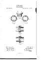
- Figures 1 and 2 represent a plan view of the outer face of each coupling.
- Figs. 3 and 4 are longitudinal sections of the same, and
- Fig. 5 is an elevation of each half of the coupling.
- each half of the coupling A B To the meeting ends of each half of the coupling A B are attached two bars, C C, projecting from the inner surface, and bent outward at a right angle at the ends, as shown in Fig. 5, so as to form a catch. These bars are placed directly opposite each other.
- In the inner edges of each half of the coupling are slots or openings D D, placed opposite each other.
- the inner edge E forms a rim, the thickness of which at the opening or slot D is about equal to the length of the bar C below the angular projection, and increases in width, so as to form an incline on the under side, as shown at a a, Fig. 4.
- the two faces of the coupling are provided each with a packing, G, of any suitable material.
- Hose-couplings are subjectedto very rough usage, being dragged over rough ground and stones; and as other similar devices for coupling are all outside, the grooves would be filled with dirt, and be difficult to connect. This coupling is entirely protected, as the devices are all inside.
- the operation' of attaching and detaching the coupling is very simple, and can be performed in an instant. It is done by simply inserting the projections or bars C C in the openings D D.
- the projections C C catch on the inclines a a, and by giving a slight turn to one part of the coupling the two parts are firmly secured to each other.
- the projecting bars or catches C C and the inclined recesses a. a arranged on the inner side of the coupling, substantially as and for the purpose set forth.
Landscapes
- Engineering & Computer Science (AREA)
- General Engineering & Computer Science (AREA)
- Mechanical Engineering (AREA)
- Earth Drilling (AREA)
Description
C. M. CHASE.
HOSE-COUPLING.
No.185,494;. Patented Dec..19, 1876.
WITNESSES INVENTU UNITED STATES PATENT DFFICE.
CHARLES M. CHASE, OF BOSTON, ASSIGNOR TO HIMSELF AND ARTHUR C. GOULD, OF BROOKLINE, MASSACHUSETTS.
IMPROVEMENT IN HOSE-COUPLINGS.
Specification forming part of Letters Patent No. 185,494, dated December 19, 1876; application filed October 12, 1876.
To all whom it may concern:
Be it known that I, CHARLES M. CHASE, of Boston, in the county of Sufi'olk and State of Massachusetts, have invented a Hose-Coupling, of which the following is a specification:
The object of my invention is to produce a simple and efficient device for coupling hose; and the invention consists in providing each half of a coupling with two projecting catches and two slots or openings, into which the said catches are inserted, and engage with an inclined lip or edge, so that by turning the couplings the two portions will be securely held together. The catches and slots are so arranged that any two halves of coupling will fit each other, so that any two parts of a hose can be readily connected to each other and firmly secured.
In the drawings, Figures 1 and 2 represent a plan view of the outer face of each coupling. Figs. 3 and 4 are longitudinal sections of the same, and Fig. 5 is an elevation of each half of the coupling.
To the meeting ends of each half of the coupling A B are attached two bars, C C, projecting from the inner surface, and bent outward at a right angle at the ends, as shown in Fig. 5, so as to form a catch. These bars are placed directly opposite each other. In the inner edges of each half of the coupling are slots or openings D D, placed opposite each other. The inner edge E forms a rim, the thickness of which at the opening or slot D is about equal to the length of the bar C below the angular projection, and increases in width, so as to form an incline on the under side, as shown at a a, Fig. 4. The two faces of the coupling are provided each with a packing, G, of any suitable material.
The advantages that this device has over former ones are simplicity of construction and protection of the coupling. Hose-couplings are subjectedto very rough usage, being dragged over rough ground and stones; and as other similar devices for coupling are all outside, the grooves would be filled with dirt, and be difficult to connect. This coupling is entirely protected, as the devices are all inside.
The operation' of attaching and detaching the coupling is very simple, and can be performed in an instant. It is done by simply inserting the projections or bars C C in the openings D D. The projections C C catch on the inclines a a, and by giving a slight turn to one part of the coupling the two parts are firmly secured to each other.
As both parts of the coupling are made precisely alike, any two can be readily attached to each other without loss of time. In ordinary couplings use is made of a male and female screw, or equivalent devices, which require a nice fitting of the parts, occasioning difficulty and loss of time in connecting together.
What I claim as my invention, and desire to secure by Letters Patent, is-
In combination with the two parts A B of a hose-couplin g, the projecting bars or catches C C and the inclined recesses a. a, arranged on the inner side of the coupling, substantially as and for the purpose set forth.
In testimony whereof I have signed my name to this specification in the presence of two subscribing witnesses.
C. M. CHASE. Witnesses:
J. H. ADAMS, ARTHUR G. GoULD.
Publications (1)
| Publication Number | Publication Date |
|---|---|
| US185494A true US185494A (en) | 1876-12-19 |
Family
ID=2254900
Family Applications (1)
| Application Number | Title | Priority Date | Filing Date |
|---|---|---|---|
| US185494D Expired - Lifetime US185494A (en) | Improvement in hose-couplings |
Country Status (1)
| Country | Link |
|---|---|
| US (1) | US185494A (en) |
Cited By (2)
| Publication number | Priority date | Publication date | Assignee | Title |
|---|---|---|---|---|
| US5857713A (en) * | 1995-10-24 | 1999-01-12 | Sakura Rubber Co., Ltd. | Coupling for hose and method of manufacturing the same |
| US6382680B1 (en) * | 1997-10-16 | 2002-05-07 | Sakura Rubber Co., Ltd. | Coupler apparatus and method of manufacturing the same |
-
0
- US US185494D patent/US185494A/en not_active Expired - Lifetime
Cited By (2)
| Publication number | Priority date | Publication date | Assignee | Title |
|---|---|---|---|---|
| US5857713A (en) * | 1995-10-24 | 1999-01-12 | Sakura Rubber Co., Ltd. | Coupling for hose and method of manufacturing the same |
| US6382680B1 (en) * | 1997-10-16 | 2002-05-07 | Sakura Rubber Co., Ltd. | Coupler apparatus and method of manufacturing the same |
Similar Documents
| Publication | Publication Date | Title |
|---|---|---|
| US459951A (en) | Hose-coupling | |
| US472342A (en) | X h hosexcouplingl | |
| US519312A (en) | Adjustable hose-coupling band | |
| US185494A (en) | Improvement in hose-couplings | |
| US806665A (en) | Hose-coupling. | |
| US383360A (en) | Hose-coupling | |
| US921368A (en) | Hose-coupling. | |
| US724324A (en) | Hose-coupling. | |
| US700798A (en) | Coupling for hose-pipes, &c. | |
| US1238218A (en) | Pipe-coupling. | |
| US1002264A (en) | Hose-coupling. | |
| US549733A (en) | limbert | |
| US825354A (en) | Pipe-coupling. | |
| US714311A (en) | Universal union or coupling. | |
| US210923A (en) | Improvement in hose-couplings | |
| US527764A (en) | Hose-coupling | |
| US744788A (en) | Hose-pipe coupling. | |
| US574743A (en) | Edwakd j | |
| US1193162A (en) | Fitz jambs lewis | |
| US948437A (en) | Hose-coupling. | |
| US197560A (en) | Improvement in pipe-clamps | |
| US189905A (en) | Improvement in hose-couplings | |
| US176769A (en) | Improvement in lightning-rod couplings | |
| US193810A (en) | Improvement in hose-couplings | |
| US487893A (en) | And charles |