US1854945A - Rectifying system - Google Patents
Rectifying system Download PDFInfo
- Publication number
- US1854945A US1854945A US419656A US41965630A US1854945A US 1854945 A US1854945 A US 1854945A US 419656 A US419656 A US 419656A US 41965630 A US41965630 A US 41965630A US 1854945 A US1854945 A US 1854945A
- Authority
- US
- United States
- Prior art keywords
- interphase
- windings
- phase
- condenser
- transformer
- Prior art date
- Legal status (The legal status is an assumption and is not a legal conclusion. Google has not performed a legal analysis and makes no representation as to the accuracy of the status listed.)
- Expired - Lifetime
Links
Images
Classifications
-
- H—ELECTRICITY
- H02—GENERATION; CONVERSION OR DISTRIBUTION OF ELECTRIC POWER
- H02M—APPARATUS FOR CONVERSION BETWEEN AC AND AC, BETWEEN AC AND DC, OR BETWEEN DC AND DC, AND FOR USE WITH MAINS OR SIMILAR POWER SUPPLY SYSTEMS; CONVERSION OF DC OR AC INPUT POWER INTO SURGE OUTPUT POWER; CONTROL OR REGULATION THEREOF
- H02M7/00—Conversion of AC power input into DC power output; Conversion of DC power input into AC power output
- H02M7/02—Conversion of AC power input into DC power output without possibility of reversal
- H02M7/04—Conversion of AC power input into DC power output without possibility of reversal by static converters
- H02M7/06—Conversion of AC power input into DC power output without possibility of reversal by static converters using discharge tubes without control electrode or semiconductor devices without control electrode
- H02M7/066—Conversion of AC power input into DC power output without possibility of reversal by static converters using discharge tubes without control electrode or semiconductor devices without control electrode particular circuits having a special characteristic
Definitions
- My invention relates to electric systems wherein power is interchanged between direct and alternating current circuits through means comprising an electric discharge aprent circuit may be maintained substantially independent of variation in the magnitude of the direct current load or may be made to increase or decrease as this load increases.
- a 12 phase rectifying system may be made up of two 6 phase systems, each of which 1ncludes an interphase transformer, a reactor and a condenser.
- difficulty has been encountered due to the fact that the reactive voltage of the main transformer tends to cause unequal distribution. of the load between the two interphase connections, one of the interphase connections being subjected to the largest'load when the phase rotation of the maintransformer is in one direction and the other interphase connection having the largest load when the phase rotation of the main transformer is in the opposite direction.
- this difficulty is minimized or altogether obviated by the provision of an interconnection between the different interphase connections, whereby the effect of the reactive voltage generated in the main transformer windings is neutralized.
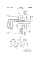
- Fig. 1 illustrates a rectifying system wherein my invention has been embodied; and Fig. 2 is an explanatory diagram relating to the operation of this system.
- This system includes alternating current supply terminals 10, direct current terminals 11 between which electric power is transmitted through a rectifier 12 and a main transformer 13.
- the transformer 13 is provided with a delta connected primary winding 14 and with four star connected secondary windings 15, 16, 17 and 18.
- the star connected secondary windings 15 and 16 are arranged to have their neutral terminals interconnected through an interphase transformer 19 and the star connected secondary windings 17 and 18 are likewise arranged to have their neutral terminals interconnected through an interphase transformer 20.
- a winding 21 provided with a mid-terminal 22 which is connected to the negative side of the direct current circuit through a smoothing reactor 28, a switch 24:, the winding 25 of a reactor 26, and the winding 27 of a reactor 28.
- the transformer windings 15 and 16 form in effect a 6 phase system.
- the interphase connection of this system includes theinterphase transformer 19, the reactor 26 and a condenser 29.
- the interphase connection of the 6 phase system formed by the windings 17 and 18 includes the interphase transformer 20, a condenser 30 and the reactor 28.
- the two 6 phase systems are so arranged as to be 30' electrical degrees out of phase with each other and thus produce 12 phase operation of the rectifier 12.
- the two 6 phase systems are arranged to be 30 electrical degrees out of phase with each other.
- the rectifier is in operation the currents in the circuits of the condensers 29 and 30 include two triple frequency alternating currents which are in quadrature with one another. These two currents are indicated in Fig. 2 by the curve 29' which indicates the triple frequency current transmitter through the interphase connection including the condenser 29 and a curve 30 which represents the triple frequency current transmitted through the interphase system including the condenser 30.
- the coils 31 and 32 are provided. These two coils a re connected in the different interphase connections as previously explained, and may be wound on a common core or may be suitably interlaced if a core is not used. In either case they are so designed that the voltages generated in them have opposite polarity and function to eliminate the efl'ect of the reactive voltage generated in the main transformer windings. If these coils are so designed that their voltage is equal or equivalent to the reactive voltage of the main transformer windings, they will have an exactly equal and opposite effect so that the load will be equally divided between the two 6 phase systems.
- the coils 31 and 32 may be connected at the neutral connections between the main transformer secondary windings and the interphase transformers.
- the advantage ofso connecting these coils is that the exciting currents for the interphase transformers will be transmitted through them.
- the disadvantage is that the reactor will have to be made larger in order to carry the direct current in addition to the alternating current.
Landscapes
- Engineering & Computer Science (AREA)
- Power Engineering (AREA)
- Ac-Ac Conversion (AREA)
Description
April 19, 1932.
T. c. LENNOX 1,854,945
RECTIFYING SYSTEM Filed Jan. 9, 1930 Fig. I.
Inventor: Thor-has C. Lennox, 9
His Attorney.
Patented Apr. 19, 1932 v Z UNITED STATES PATENT OFFICE THOMAS C. LENNOX, F PITTSFIELD, MASSACHUSETTS, ASSIGNOR TO GENERAL ELEC- TRIC COMPANY, A CORPORATION OF NEW YORK RECTIFYING SYSTEM Application filed January 9, 1930. Serial No. 419,656.
My invention relates to electric systems wherein power is interchanged between direct and alternating current circuits through means comprising an electric discharge aprent circuit may be maintained substantially independent of variation in the magnitude of the direct current load or may be made to increase or decrease as this load increases.
' In my copending application Serial No. 347,399, filed March 15, 1929, and assigned to the same assignee as the present application, is disclosed a rectifying apparatus wherein voltage regulation of the direct current circuitis eflected by means of an interphase connection including predetermined inductive and capacitive impedances so arranged as to produce an eflective impedance which varies inversely as a direct current load. This interphase connection may include a reactor, an auxiliary transformer and a condenser arranged to produce such variation in the impedance of the transformer connection that the output voltage of the rectifier will rise as the direct current load increases, the extent of this rise and the degree of compounding being determined by the constants of the interphase circuit connections.
It is sometimes desirable to utilize the above interphase connection to regulate the voltage of '12 phase rectifiers or the like. As is well understood by those skilled in the art, a 12 phase rectifying system may be made up of two 6 phase systems, each of which 1ncludes an interphase transformer, a reactor and a condenser. In the application of the above invention to: such systems, difficulty has been encountered due to the fact that the reactive voltage of the main transformer tends to cause unequal distribution. of the load between the two interphase connections, one of the interphase connections being subjected to the largest'load when the phase rotation of the maintransformer is in one direction and the other interphase connection having the largest load when the phase rotation of the main transformer is in the opposite direction.
In accordance with my invention this difficulty is minimized or altogether obviated by the provision of an interconnection between the different interphase connections, whereby the effect of the reactive voltage generated in the main transformer windings is neutralized.
My invention will be better understood from the following description when considered in connection with the accompanying drawings, and its scope will be pointed out in the appended claims.
Referring to the drawings, Fig. 1 illustrates a rectifying system wherein my invention has been embodied; and Fig. 2 is an explanatory diagram relating to the operation of this system. This system includes alternating current supply terminals 10, direct current terminals 11 between which electric power is transmitted through a rectifier 12 and a main transformer 13. The transformer 13 is provided with a delta connected primary winding 14 and with four star connected secondary windings 15, 16, 17 and 18. The star connected secondary windings 15 and 16 are arranged to have their neutral terminals interconnected through an interphase transformer 19 and the star connected secondary windings 17 and 18 are likewise arranged to have their neutral terminals interconnected through an interphase transformer 20. Connected between the interphase transformers 19 and 20 is a winding 21 provided with a mid-terminal 22 which is connected to the negative side of the direct current circuit through a smoothing reactor 28, a switch 24:, the winding 25 of a reactor 26, and the winding 27 of a reactor 28.
The transformer windings 15 and 16 form in effect a 6 phase system. The interphase connection of this system includes theinterphase transformer 19, the reactor 26 and a condenser 29. The interphase connection of the 6 phase system formed by the windings 17 and 18 includes the interphase transformer 20, a condenser 30 and the reactor 28.
As previously explained, the effect of the reactive voltage in the main transformers is till to cause the 6 phase system including the windings 15 and 16, to take more load than the 6 phase system including the windings 17 and 18 when the phase rotation of the transformer 13 is in one direction and to cause the 6 phase system including the windings 17 and 18 to take more load than the 6 phase system including the windings 15 and 16 when the phase rotation of the transformer 13 is in the opposite direction. This result is avoided. by the provisionof windings 31 and 32 which are inductively related with one another and are each connected in a different interphase connection. p
The two 6 phase systems are so arranged as to be 30' electrical degrees out of phase with each other and thus produce 12 phase operation of the rectifier 12.
In order to produce 12 phase operation of the rectifier 12, the two 6 phase systems are arranged to be 30 electrical degrees out of phase with each other. hen the rectifier is in operation the currents in the circuits of the condensers 29 and 30 include two triple frequency alternating currents which are in quadrature with one another. These two currents are indicated in Fig. 2 by the curve 29' which indicates the triple frequency current transmitter through the interphase connection including the condenser 29 and a curve 30 which represents the triple frequency current transmitted through the interphase system including the condenser 30.
Due to the fact that the secondary windings 15, 16, 17 and 18 are very closely interlaced and the reactive Voltage generated in one of these windings is effective in the other, one of the 6 phase systems is subjected to a larger load than the other. In Fig. 2 the portions a, b, 0, d, e, f, g of the curve 30 represent the current in the interphase connection including the condenser 30 and the parts a 6 0 03 ,6 i of curve 29 represent the triple frequency currents in the interphase connection including the condenser 29.
It will be observed that when the interphase system including the condenser 30 commutates from c to (Z, the reactive voltage in the main transformer which opposes the change will be effective in the direction 6Z-0, and as it will also acton the system including the condenser 29, it will tend to make the current of that system change in the same direction, consequently causing the current to take the form d 6 instead of (Z 6 This will be repeated every half cycle in the interphase current indicated by thecurves in Fig. 2.
When commutation occurs in the system including the condenser 29 as on 0 and (L, the reactive voltage in the main transformer is effective in the direction (Z c and will c0nsequently cause the current in the system, including the condenser 30, to assume the form T indicated between b and 0,. This will be repeated every half cycle as indicated in Fig. 2.
The net result of this condition is that the system including the condenser 30 takes more than one-half the total load on the rectifier, the 12 phase operation of the rectifier is disturbed and the equipment is not utilized economically. If the phase rotation v of the 3 phase current supplied to the primary winding 14 of the main transformer is reversed,
this condition is changed so that the s including the condenser 29 will take the larger current and the system including the condenser 30 the smaller.
In order to insure an equal distribution of the load between the two 6 phase systems, the coils 31 and 32 are provided. These two coils a re connected in the different interphase connections as previously explained, and may be wound on a common core or may be suitably interlaced if a core is not used. In either case they are so designed that the voltages generated in them have opposite polarity and function to eliminate the efl'ect of the reactive voltage generated in the main transformer windings. If these coils are so designed that their voltage is equal or equivalent to the reactive voltage of the main transformer windings, they will have an exactly equal and opposite effect so that the load will be equally divided between the two 6 phase systems.
It will be apparent that the coils 31 and 32 may be connected at the neutral connections between the main transformer secondary windings and the interphase transformers. The advantage ofso connecting these coils is that the exciting currents for the interphase transformers will be transmitted through them. The disadvantage is that the reactor will have to be made larger in order to carry the direct current in addition to the alternating current.
'lVhile I have shown and described my invention with reference to an electric discharge apparatus of the vapor electric type and. m which all of the anodes are enclosed in a single vessel it will be understood that I do not wish to be limited thereto, since any other suitable arangement'of electric discharge apparatus in which current is caused to flow unidirectionally between a negative conductor and a plurality of anodes, for rectifyi or like puprposes, may be employed. &us while I have shown only a single embodiment of my invention it will be understood that manymodifications may be made therein and that I contemplate by the appended claims to cover any such modification as falls within the truespirit and scope of my invention.
What I claim as new and esire to secure by Letters Patent of the United States is:
1. The combination of two polyphase systems each provided with main transformer windings and with an interphase connection between the neutral terminals of said windings, an electric discharge apparatus, direct current terminals connected directly to said interphase connection and through said apparatus to said windings, and means interposed between said interphase connections for neutralizing an effect of the reactive voltage of said windings.
2. The combination of two polyphase systems each provided with main transformer windings and with an interphase connection between the neutral terminals of said windings, an electric discharge apparatus, direct current terminals connected directly to said interphase connection and through said apparatus to said windings, and impedance means including coils inductively related with one another and interposed in different interphase connections for equalizing the loads of said polyphase systems.
3. The combination of two polyphase systems each provided with main transformer windings and with an interphase connection including a condenser connected between the neutral terminals of said windings, an electric discharge apparatus, direct current terminals connected directly to said interphase connection and through said apparatus to said windings, and means interposed between said interphase connections for neutralizing an effect of the reactive voltage of said windin s.
el. The combination of two polyphase systems each provided with main transformer windings and with an interphase connection including a reactor connected between the neutral terminal-s of said windings, an electric discharge apparatus, direct current terminals connected directly to the said interphase connection and through said apparatus to said windings, and means interposed between said interphase connections for neutralizing an effect of the reactive voltage of said windings.
5. The combination of two polyphase systems each provided with main transformer windings and with an interphase connection including a condenser and a reactor connected between the neutral terminals of said windings, an electric discharge apparatus, direct current terminals connected directly to said interphase connection and through said apparatus to said windings, and means interposed between said interphase connections for neutralizing an effect of the reactive voltage of said windings.
6. The combination of two 6-phase systems each provided with two 3-phase main transform-er windings and with an interphase connection including a reactor connected between the neutral terminals of said windings, an electric discharge apparatus, direct currentterminals connected directly to the said interphase connection and through said apparatus to said windings, and means interposed between said interphase connections for neutralizing an effect of the reactive voltage of said windings.
7. The combination of two 6-phase sys-
Priority Applications (1)
| Application Number | Priority Date | Filing Date | Title |
|---|---|---|---|
| US419656A US1854945A (en) | 1930-01-09 | 1930-01-09 | Rectifying system |
Applications Claiming Priority (1)
| Application Number | Priority Date | Filing Date | Title |
|---|---|---|---|
| US419656A US1854945A (en) | 1930-01-09 | 1930-01-09 | Rectifying system |
Publications (1)
| Publication Number | Publication Date |
|---|---|
| US1854945A true US1854945A (en) | 1932-04-19 |
Family
ID=23663170
Family Applications (1)
| Application Number | Title | Priority Date | Filing Date |
|---|---|---|---|
| US419656A Expired - Lifetime US1854945A (en) | 1930-01-09 | 1930-01-09 | Rectifying system |
Country Status (1)
| Country | Link |
|---|---|
| US (1) | US1854945A (en) |
-
1930
- 1930-01-09 US US419656A patent/US1854945A/en not_active Expired - Lifetime
Similar Documents
| Publication | Publication Date | Title |
|---|---|---|
| US2307527A (en) | Electrical induction apparatus | |
| US2000189A (en) | Regulated rectifier | |
| US1854945A (en) | Rectifying system | |
| US1952052A (en) | Electric valve converting apparatus | |
| US3440516A (en) | Transformer and capacitor apparatus for three-phase electrical systems | |
| US2224755A (en) | Electrical transformation apparatus | |
| US3193754A (en) | Reduced impedance transformer and rectifier busing | |
| US1738726A (en) | Regulating device for electrical systems | |
| US1947231A (en) | Electric translating circuits | |
| US2808519A (en) | Voltage equalizer for unbalanced loads | |
| US1979699A (en) | Balance coil | |
| US2195296A (en) | Electric translating system | |
| US1957229A (en) | Electric valve converting apparatus | |
| US1783804A (en) | Electric system | |
| US2195308A (en) | Electric translating system | |
| US1752109A (en) | Electrical system | |
| US1860175A (en) | Two-phase circuit connection for vapor electric devices | |
| US1976580A (en) | Current translating system | |
| US1986604A (en) | Rectifier compounding system | |
| US1999013A (en) | Electric power converting apparatus | |
| US1894827A (en) | Polyphase system | |
| US1712502A (en) | Apparatus for obtaining direct current from alternating current by means of polyphase rectifiers | |
| US1876428A (en) | lennox | |
| US1895370A (en) | Electric translating system | |
| US2714700A (en) | Electric power system |