US1854944A - Means and method for making metallic bellows - Google Patents
Means and method for making metallic bellows Download PDFInfo
- Publication number
- US1854944A US1854944A US345774A US34577429A US1854944A US 1854944 A US1854944 A US 1854944A US 345774 A US345774 A US 345774A US 34577429 A US34577429 A US 34577429A US 1854944 A US1854944 A US 1854944A
- Authority
- US
- United States
- Prior art keywords
- flanges
- rolls
- crimping
- wafers
- roll
- Prior art date
- Legal status (The legal status is an assumption and is not a legal conclusion. Google has not performed a legal analysis and makes no representation as to the accuracy of the status listed.)
- Expired - Lifetime
Links
- 238000000034 method Methods 0.000 title description 9
- 235000012431 wafers Nutrition 0.000 description 37
- 238000002788 crimping Methods 0.000 description 29
- 230000000712 assembly Effects 0.000 description 13
- 238000000429 assembly Methods 0.000 description 13
- 238000013459 approach Methods 0.000 description 10
- 230000000694 effects Effects 0.000 description 10
- 239000011324 bead Substances 0.000 description 6
- 239000002184 metal Substances 0.000 description 5
- 230000008520 organization Effects 0.000 description 4
- 238000010438 heat treatment Methods 0.000 description 3
- 230000013011 mating Effects 0.000 description 3
- 230000002093 peripheral effect Effects 0.000 description 3
- 238000003825 pressing Methods 0.000 description 3
- 238000009987 spinning Methods 0.000 description 3
- 230000005484 gravity Effects 0.000 description 2
- 238000005476 soldering Methods 0.000 description 2
- 230000001133 acceleration Effects 0.000 description 1
- 230000002301 combined effect Effects 0.000 description 1
- 230000000052 comparative effect Effects 0.000 description 1
- 238000010276 construction Methods 0.000 description 1
- 238000013461 design Methods 0.000 description 1
- 238000004519 manufacturing process Methods 0.000 description 1
- 239000000463 material Substances 0.000 description 1
- 238000012986 modification Methods 0.000 description 1
- 230000004048 modification Effects 0.000 description 1
- 238000002360 preparation method Methods 0.000 description 1
- 238000011160 research Methods 0.000 description 1
- 230000000717 retained effect Effects 0.000 description 1
- 238000005096 rolling process Methods 0.000 description 1
Images


Classifications
-
- B—PERFORMING OPERATIONS; TRANSPORTING
- B21—MECHANICAL METAL-WORKING WITHOUT ESSENTIALLY REMOVING MATERIAL; PUNCHING METAL
- B21D—WORKING OR PROCESSING OF SHEET METAL OR METAL TUBES, RODS OR PROFILES WITHOUT ESSENTIALLY REMOVING MATERIAL; PUNCHING METAL
- B21D15/00—Corrugating tubes
- B21D15/04—Corrugating tubes transversely, e.g. helically
- B21D15/06—Corrugating tubes transversely, e.g. helically annularly
-
- Y—GENERAL TAGGING OF NEW TECHNOLOGICAL DEVELOPMENTS; GENERAL TAGGING OF CROSS-SECTIONAL TECHNOLOGIES SPANNING OVER SEVERAL SECTIONS OF THE IPC; TECHNICAL SUBJECTS COVERED BY FORMER USPC CROSS-REFERENCE ART COLLECTIONS [XRACs] AND DIGESTS
- Y10—TECHNICAL SUBJECTS COVERED BY FORMER USPC
- Y10T—TECHNICAL SUBJECTS COVERED BY FORMER US CLASSIFICATION
- Y10T29/00—Metal working
- Y10T29/49—Method of mechanical manufacture
- Y10T29/49826—Assembling or joining
- Y10T29/49877—Assembling or joining of flexible wall, expansible chamber devices [e.g., bellows]
-
- Y—GENERAL TAGGING OF NEW TECHNOLOGICAL DEVELOPMENTS; GENERAL TAGGING OF CROSS-SECTIONAL TECHNOLOGIES SPANNING OVER SEVERAL SECTIONS OF THE IPC; TECHNICAL SUBJECTS COVERED BY FORMER USPC CROSS-REFERENCE ART COLLECTIONS [XRACs] AND DIGESTS
- Y10—TECHNICAL SUBJECTS COVERED BY FORMER USPC
- Y10T—TECHNICAL SUBJECTS COVERED BY FORMER US CLASSIFICATION
- Y10T29/00—Metal working
- Y10T29/53—Means to assemble or disassemble
- Y10T29/53996—Means to assemble or disassemble by deforming
Definitions
- a movement of approach during rapid rota-- tion of a bellows assemblytherebetween may be utilized for effecting a deformation of flanges upon 'said wafers,s'o crimping the same as permanently to unite the edges thereof.
- the first mentioned roll may cooperate with the latter in the mentioned rotative effect and 3 may also serve, by an opposed radial pressure,
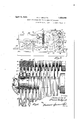
- Fig. 1 is a side elevational view, some parts pertaining thereto being broken away and various optional features being included.
- Figs. 2 and 3 are respectively end elevational views taken substantially as indicated by the arrow 2 in Fig. 1,.parts being broken away or omitted and different steps in a cycle of operation being shown, as hereinafter explained.
- Fig/i is a top plan view generally consistent with Fig. 2 but assuming a cam-operating handle to occupy such a position as is therein shown in dotted lines.
- Fig. 5 is a diagrammatic sectional view, on a larger scale, showing the preferred general manner in which pairs of flanged wafers may be interfitted in preparation for the-uniting operations for which this machine is designed, some details of an optional piling means being shown.
- Fig. 6 is an enlarged but'fragmentary view, taken in substantially the plane indicated by .the line 66 of Fig. 3-.
- a base late 10 may directly or indirectly support a ellows-spinning organization 11, a motor 12, a bellows.
- handling carriage 13 (including a slider M operated mechanical advantage cam organization 16,manipulable to effect a movement of approach between an inner crimping roll 17 serving as a mandrel roll and an outer crimping roll 18 of larger diameter than roll 17 included in the mentioned bellows-spinning organization.
- the crimping rolls 17 and 18 are shownas terminally mounted upon shafts 19 and 20; and these shafts are not only mounted upon and relatively movable with so-called spinner arms 21 and 22, pivoted upon a main shaft 23, but driven, preferably from said main shaft, by means of separate pinions 24 and 25.
- the pinion 25 may be driven from said master gear by means such as an intermediate gear 27.
- gears are shown as protected by a housing 28; and the master gear, or its equivalent, may be driven from the motor 12 by means including a drive pinion 29, shown as mounted upon a shaft 30 and as adapted to be given a suitable rate of rotation through a multiplying or reducing gear train housed within gear box 31.
- means such as a horizontally movable cam 31, comprised in the mentioned cam organization 16 and shown as engaging rolls 32, 33 upon horizontally extending cam arms 34, 35, respectively integral with the mentioned spinner arms 21, 22, may be employed to effect a suit ably timed movement of approach between the crimping rolls 17 and 18, after a wafer assembly has been disposed therebetween or while said assembly is dependently supported by one of said rolls.
- Horizontal movement may be imparted to the cam 31, or its equivalent, by means such as a rack 36 and a pinion 38.'
- the latter is shown as rotatable by a suitable crank 39; and parts here referred to are shown as suit ably supported and protected by means of a housing 40.
- Means such as a"tension spring 41 may be employed to bias the spinner arms 21 and 22, and thereby the rolls 17 and 18, toward the open relative position illustrated in Figs. 1 and 2; and itv will be obvious that the specific configuration of said rolls will depend upon the configuration given mentionedparts and upon the shape, the dimensions and the number of wafers employed in each assembly, to constitute a bellows.
- the roll 17 being intended to be received within, and the roll 18 being intended externally to engage, a
- annular depressions 42 provided in the exterior in the roll 17, are shown as staggered relatively to similar but narrower annular depressions 43, provided in the roll 18; and, in order that the spinning of a wafer assembly upon the roller'17, or between rollers 17 and 18, shall effect the de sired crimping deformations of inwardly extending and outwardly extending flanges upon the mentioned wafers, the respective annular depressions 42 and 43 are shown as provided with special grooves 44 and 45 in the bottoms thereof,-said depressions being respectively adapted to receive mating arcuate parts which provide inwardly extending corrugations and outwardly extending corrugations of the bellows produced from said wafer assemblies.
- the wafers 46 are each provided with an inwardly extending flat flange 48, an outwardly extending flat flange 49, and a substantially cylindrical flange 50; and that the wafers 47 each comprise an outer flat flange 51, an inner flat flange 52 and an inner cylindrical flange 53,-the flanges 51 being adapted to so interfit within the flanges 50 as to engage the flanges 49, and the flanges 48 being adapted to so interfit within the flanges 53 as to engage the flanges
- the opposed surfaces ofthe mentioned flat flanges, or any of said surfaces may be tinned in advance of assembly, and/or a suitable soldering paste may be interposed in advance of or during assembly; and the fit between the mentioned cooperating flanges may be such, even though said wafers are formed of a very
- the slider 14 being shown as having a dovetailed connection with the base plate 10 (by means which may include a removable side element 54, shown as retained by means of screws 55)
- the loading rack 15 (carried by said slider and completing a carriage which is manipulable by means such as the handle 56) may include one or more channeled handling elements such as rollers 57, 58 freely rotatable upon shafts 59 and 60,said rollers being shown as providedwith annular corrugaupon the rolls 57 58, upon the.
- outer pairs of concavities 65 (received within annular depressions 43 in roll 18 and cooperating to form corrugations or arches 67 by union of outer flanges 49, 50 and 51) and inner-pairs of concavities 66, 66' (forming inward corrugations respectivecrimping rolls may be spaced apart by compartively thick beads 43" and-- by thinner beads 44 of any appropriate typewIt is important to note that the beads 43' are not shown as exteriorly contacting with the bot toms of the mentioned inward corrugations or arches 68 as received in annular depressions 42 of roll-17; and that the beads 44' r arches curved in two planes and/or rotational effects in contributing to the radial
- the combined effects of rotation and gravity, and a friction due thereto may promptly cause'a partial or complete crimping of the flanges 53, at the same time so flattening or drawing together (by centrifugal effect) the slightly conical webs 69, 69 as topermit free entrance of the outward corrugations 67 between the beads 43 of roll 1 8-,the bottoms of whose grooves 43 may have a pheripheral speed not far different from that acquired by the flanges 50 by the time that the latter closely approach 1 the grooves 45.
- the comparative rigidity that has in the meantime been acquired through the action of centrifugal force upon the webs 69, 69 may then Joe suflicient (especially in-,view of the design of'the wafers and the lateral support rendered available by beads 43', 44, and in view of the fric-.
- crank 39 or its equivalent (whose movements may be limited by means such as the engagement of a pin 39a with the ends of a slot 395) from a position such as that shown in Fig. 2 to positions such as those shown in Figs. 2 and 4 may then replace the crimped bellows upon the loading rack 15.
- a new wafer assembly may then be substituted or arches 68 by union of innerfianges 48 5 thereon in readiness for a' repetition of the 53) a'rerespectively spaced apart by relative- 1y flat but slightly conical intermediate zones or webs 69, 69; and also the peripheral or annular depressions 42, 43 provided in the use of a lower roller or rollers 57, 58 whether idle or driven, as a platen element.
- electrical means may, if desired, be soassociated with the rolls 17, 18 (as, by partially embedding the same therein) that, after a desired approach between the spinner arms (shown as carrying opposable contact-74, 75) and/or after such a crimping of the flangesas enables the same to enter the grooves 44, 45, a resistance heating system, shown as comprising wires 7 6, 77 may be automatically completed, for a flange-softening.
- Collector rings 78, 79, with which embedded heating elements 80, 80' (see Fig. 6) are connected, are shown as constantly engaged by brushes 81, 82; and collector rings 83, 84,
- heating elements 80 are shown as being constantly engaged by brushes 86, 87.
- a cam 88 rigidly con nected with a rack 89, is shown as horizontally movable by a second pinion 90, mount ing upon the same shaft 91 which carries the roll-positioning pinion 38,-the cams 31 and 88 being, when used in the manner referred to, so proportioned as to be successive in their effects.
- the cam 88 isshown as steadiedby a guide roller 92 and as contacting a cam roller 93, mounted upon the slider 14; this slider is shown as biased toward its inner position by means comprising a flexible element 94, carried over a pulley 95 and connected with constantly-acting means such as a spring or weight 96,diagrammatic ally suggestedin Fig. 1;
- the rack 89 is shown 'as slidably reta ned by a removable guide plate 98; and the various-units referred to screws 99; but it will be obvious that these.
- optional features and details are here re-H are shown as secured to the base 10 by bolts or ferred to primarily'for the sake of completeness, being relatively immaterial to the main invention claims.
- Amethod ,of crimping flanges to form bellows from assemblies of metallic wafers which comprises: rapidly rotating wafer assemblies, applying externalpressure only to said flanges, during such rotation, for crimping them, and developing by said rotation sufficient centrifugal force substantially to prevent deformation of the wafers except at the zones where crimping pressure is apsures to said flanges during rotation, and developing by said rotation suflicient centrifugal force substantially to prevent deformation of the wafers except at the zones where rolling pressure is applied.
- a method of producing'bello'ws- which comprises: forming wafers with opposable flanges respectively near inner edges and outer edges thereof,'which flanges form parts assembling said wafers to form inner and outer corrugations which complete said arches; and crimping said flanges by applying pressure thereto while so rotating the assembly that said arches remain substantially rigid under said pressure, said arches being interiorly unsupported.
- a method of producing bellows which comprises: forming wafers with opposable flanges respectively near inner edges and outer edges thereof, which flanges form parts of arches having curvatures in two planes; assembling said wafers to form inner and outer corrugations" which completeg said arches; and crimping said flanges by applying pressure thereto while so supporting the assembly that said arches remain rigid under said pressure,an outer set of flan-ges'being crimpedby an inward pressure applied during continued rotation.
- a method of producing bellows which comprises: forming wafers with opposable flanges respectively near inner edges and outer edges thereof, which flanges form parts of arches having curvatures in two planes;
- a combination as defined in'claim 7 in which the means for rotating the bellows assembly comprises a hi h speedtransmission arranged to rotate sai vgrooved rolls.
Landscapes
- Engineering & Computer Science (AREA)
- Mechanical Engineering (AREA)
- Container, Conveyance, Adherence, Positioning, Of Wafer (AREA)
Description
April 19, 1932. c. 1.. LEE ET AL.
MEANS AND METHOD FOR MAKING METALLIC BELLOWS 3 Sheets-Sheet l Filed March 9, 1929 g rvumtow C'fi'a'r/ks [ea & 5750111416: [hr/H ya]! j I Gumm April 19, 1932. c. 1.. LEE ET'AL MEANS AND METHOD FOR MAKING'METALLIC BELLOWSv 5 Sheets-Sheet 2 Filed Match 9 1929 April 19, 1932. c. L. LEE AL 1,854,944
MEANS AND METHOD FOR MAKING METALLIC BELLOWS Filed March 9, 1929 3 Sheets-Sheet 5 JTVUL'YJ OM I [fiat/v.4 Elie: L j v flame: C azzzg fryf provide means for advantageously position- UNITED STATES PATENT OFFICE cnannns L. LEE, 0']? narrow, onro, um THOMAS cfvAN nnomr'r, or nn'rnon', 111cmem, assreivons 'ro GENERAL MOTORS RESEARCH conromzrron, or mrrnorr, MICHIGANI A' con-ronarlolv or DELAWARE v MEANS AND METHOD FOR MAKING METALIiIC IBELLOWS Application filed March 9, 1929. Serial No. 345,774. 1
a movement of approach during rapid rota-- tion of a bellows assemblytherebetween, may be utilized for effecting a deformation of flanges upon 'said wafers,s'o crimping the same as permanently to unite the edges thereof. a
It is a further object of thisvinvention to provide a'technique initially relying upon a frictional engagement which may bepartly 2 due to gravity, to effect both an acceleration and a rapid rotation of wafer assemblies and a .crimping .of inwardly extending flanges through engagement thereof with an inner crimping roll; and, in preferred embodiments of said invention, anouter crimping element, such as'a suitably grooved complemental roll,
movable relatively to but always spaced from.
the first mentioned roll, may cooperate with the latter in the mentioned rotative effect and 3 may also serve, by an opposed radial pressure,
to deform outwardly extending flanges incidentally or subsequently to the mentioned deformation of the inwardly extending flanges,--arches of which are formed'by mating parts being interiorly unsupported and said crimping elements being preferably rotated'in opposite directions and at different peripheral speeds during a cam-controlmovement of approach therebetween.
It is a further object of this inventon to ing wafer assemblies for engagement by said rolls; and said rolls may be provided with staggered or grooved depressions which are tion, but a-centrifugal action which is favorshapedto receive mating parts providing able to an enhancement of the radial rigidity of, the mentioned wafer assemblies,-disposing and supporting said flanges suitably to the desired gentle but reliable crimping effect by or during entrance there f into sai .to those disclosed in Patent No. 1,607,200,
granted November 16 1926 to Kettering and Lee, said wafers being separately claimed in Patent #1,756,911 dated April 29, 1930 on an application filed by Charles L. Lee, may
be best appreciated from the following description of an illustrative embodiment there-' of taken in connection with the appended claims" and accompanying drawings.
Fig. 1 is a side elevational view, some parts pertaining thereto being broken away and various optional features being included.
Figs. 2 and 3 are respectively end elevational views taken substantially as indicated by the arrow 2 in Fig. 1,.parts being broken away or omitted and different steps in a cycle of operation being shown, as hereinafter explained.
'Fig/i is a top plan view generally consistent with Fig. 2 but assuming a cam-operating handle to occupy such a position as is therein shown in dotted lines.
' Fig. 5 is a diagrammatic sectional view, on a larger scale, showing the preferred general manner in which pairs of flanged wafers may be interfitted in preparation for the-uniting operations for which this machine is designed, some details of an optional piling means being shown.
Fig. 6 is an enlarged but'fragmentary view, taken in substantially the plane indicated by .the line 66 of Fig. 3-.
Referring to details of that specific embodiment from the invention which has been taken as an illustration, a base late 10 may directly or indirectly support a ellows-spinning organization 11, a motor 12, a bellows.
handling carriage 13 (including a slider M operated mechanical advantage cam organization 16,manipulable to effect a movement of approach between an inner crimping roll 17 serving as a mandrel roll and an outer crimping roll 18 of larger diameter than roll 17 included in the mentioned bellows-spinning organization.
The crimping rolls 17 and 18 are shownas terminally mounted upon shafts 19 and 20; and these shafts are not only mounted upon and relatively movable with so-called spinner arms 21 and 22, pivoted upon a main shaft 23, but driven, preferably from said main shaft, by means of separate pinions 24 and 25. In order oppositely to rotate said pinions, and thereby the crimping rolls 17 and 18, assuming the pinion 24 to be directly engaged by a master gear 26 upon the shaft 23, the pinion 25 may be driven from said master gear by means such as an intermediate gear 27. All of said gears are shown as protected by a housing 28; and the master gear, or its equivalent, may be driven from the motor 12 by means including a drive pinion 29, shown as mounted upon a shaft 30 and as adapted to be given a suitable rate of rotation through a multiplying or reducing gear train housed within gear box 31.
Regardless of the means, if any, employed to position successive wafer assemblies between the crimping rolls 17 and 18, means such as a horizontally movable cam 31, comprised in the mentioned cam organization 16 and shown as engaging rolls 32, 33 upon horizontally extending cam arms 34, 35, respectively integral with the mentioned spinner arms 21, 22, may be employed to effect a suit ably timed movement of approach between the crimping rolls 17 and 18, after a wafer assembly has been disposed therebetween or while said assembly is dependently supported by one of said rolls.
Horizontal movement may be imparted to the cam 31, or its equivalent, by means such as a rack 36 and a pinion 38.' The latter is shown as rotatable by a suitable crank 39; and parts here referred to are shown as suit ably supported and protected by means of a housing 40.
Means such as a"tension spring 41, shown as interposed between the cam-actuated arms 34 and 35, may be employed to bias the spinner arms 21 and 22, and thereby the rolls 17 and 18, toward the open relative position illustrated in Figs. 1 and 2; and itv will be obvious that the specific configuration of said rolls will depend upon the configuration given mentionedparts and upon the shape, the dimensions and the number of wafers employed in each assembly, to constitute a bellows. In the form shown, the roll 17 being intended to be received within, and the roll 18 being intended externally to engage, a
wafer assembly, annular depressions 42 provided in the exterior in the roll 17, are shown as staggered relatively to similar but narrower annular depressions 43, provided in the roll 18; and, in order that the spinning of a wafer assembly upon the roller'17, or between rollers 17 and 18, shall effect the de sired crimping deformations of inwardly extending and outwardly extending flanges upon the mentioned wafers, the respective annular depressions 42 and 43 are shown as provided with special grooves 44 and 45 in the bottoms thereof,-said depressions being respectively adapted to receive mating arcuate parts which provide inwardly extending corrugations and outwardly extending corrugations of the bellows produced from said wafer assemblies.
Assuming the mentioned assemblies to be built up from pairs of interfitting wafers such as are separately shown at 46 and 47, Fig. 5, it will be seen that the wafers 46 are each provided with an inwardly extending flat flange 48, an outwardly extending flat flange 49, and a substantially cylindrical flange 50; and that the wafers 47 each comprise an outer flat flange 51, an inner flat flange 52 and an inner cylindrical flange 53,-the flanges 51 being adapted to so interfit within the flanges 50 as to engage the flanges 49, and the flanges 48 being adapted to so interfit within the flanges 53 as to engage the flanges If desired, the opposed surfaces ofthe mentioned flat flanges, or any of said surfaces, may be tinned in advance of assembly, and/or a suitable soldering paste may be interposed in advance of or during assembly; and the fit between the mentioned cooperating flanges may be such, even though said wafers are formed of a very thin material, as to permit a careful manual or other loading manipulation of the resultant organizations without danger of accidental disassembly; 'but it is nevertheless deemed preferable to provide mechanical means for initially positioning and finally withdrawing successive assemblies relatively to the mentioned crimping rolls.
For the purposes last referred to, the slider 14 being shown as having a dovetailed connection with the base plate 10 (by means which may include a removable side element 54, shown as retained by means of screws 55) the loading rack 15 (carried by said slider and completing a carriage which is manipulable by means such as the handle 56) may include one or more channeled handling elements such as rollers 57, 58 freely rotatable upon shafts 59 and 60,said rollers being shown as providedwith annular corrugaupon the rolls 57 58, upon the. completion of an inward movement thereof, as effected by such as thehandle 56 (said movement being preferably limited by engagement between a fixed stop 61 carried by the base plate 10, and a terminal stop 62 carried by the slider 14) it will be seen that a movement of approach between the crimping rolls 17 and 18 (assumed to be constantly and oppositely rotated through means of the general character described) may serve to lift a waferassembly 63 from the rolls 57 and v58, or the like, and incidentally to impart rapid rotation thereto-and also partially or completely .to crimp the flanges 53, duringtheir proportionatedescent into the grooves 44; and a further movement of approach between the I rolls 1'? and 18' (these being preferablyv the rolls '17 and 18 is shown also in Fig. 2,
driven, as indicated, in opposite directions, and -at slightly-different speeds) is effective to produce a similar crimping of the flanges 50, during a proportionate entrance thereof into the grooves 45 in. the roll 18.
j Loading and unloading position of the rack 15 is shown in Fig. 1 and open position of a closed? position thereof being shown in Figs. 3 and 6. Said rolls should be understood to remain, in, the illustrated embodiment, at all times spaced apart by a distance greatly'exceeding the thickness of the metal of which the respective wafers are formed;
' and it will be notedthat the very considerable length of the. relatively movable shafts 19 and 20, as also the length of the main shaft 23 (shown as rigidly supported by three separate bearing posts 64) assures an invariable parallelism of the saidshafts. A hearing for a shaft 27a, carrying the gear 27, ,is shown as provided upon an extension 22a of arm 22; and the described construction (the shafts 19, 20, and 27a of'gears 25, 26 and 27 being movable .by and concentricallywith' arms i be executed during continuous rotation of 21 and 22) will be'seen to permit the indi cated opening and closing movements to rolls 17 and 18.
. Although the principles of this invention may be applicable to the production of bellows from assemblies of variousv sorts of wafers, such as may be stamped from an impervious and pliable metal stock having a 1 uniform thickness or regionally varying in thickness, it will be noted that, in the illustrated wafers, outer pairs of concavities 65, (received within annular depressions 43 in roll 18 and cooperating to form corrugations or arches 67 by union of outer flanges 49, 50 and 51) and inner-pairs of concavities 66, 66' (forming inward corrugations respectivecrimping rolls may be spaced apart by compartively thick beads 43" and-- by thinner beads 44 of any appropriate typewIt is important to note that the beads 43' are not shown as exteriorly contacting with the bot toms of the mentioned inward corrugations or arches 68 as received in annular depressions 42 of roll-17; and that the beads 44' r arches curved in two planes and/or rotational effects in contributing to the radial rigidity of wafers while the latter undergo the described crimping of flanges. For example, as a waferassembly is lifted from the described loading rack 15 or its equivalent, by the elevation of roll 17, the combined effects of rotation and gravity, and a friction due thereto, may promptly cause'a partial or complete crimping of the flanges 53, at the same time so flattening or drawing together (by centrifugal effect) the slightly conical webs 69, 69 as topermit free entrance of the outward corrugations 67 between the beads 43 of roll 1 8-,the bottoms of whose grooves 43 may have a pheripheral speed not far different from that acquired by the flanges 50 by the time that the latter closely approach 1 the grooves 45. The comparative rigidity that has in the meantime been acquired through the action of centrifugal force upon the webs 69, 69 may then Joe suflicient (especially in-,view of the design of'the wafers and the lateral support rendered available by beads 43', 44, and in view of the fric-.
tional engagements which may result from slight difference in peripheral speed) 'to transmit a lateral thrust that is entirely adequate gently but reliably. to complete the desired crimping, as shown, of both the flanges .50 and the flanges 53.
A return of crank 39 or its equivalent (whose movements may be limited by means such as the engagement of a pin 39a with the ends of a slot 395) from a position such as that shown in Fig. 2 to positions such as those shown in Figs. 2 and 4 may then replace the crimped bellows upon the loading rack 15. Said rack being outwardly withdrawn, a new wafer assembly may then be substituted or arches 68 by union of innerfianges 48 5 thereon in readiness for a' repetition of the 53) a'rerespectively spaced apart by relative- 1y flat but slightly conical intermediate zones or webs 69, 69; and also the peripheral or annular depressions 42, 43 provided in the use of a lower roller or rollers 57, 58 whether idle or driven, as a platen element.
electrical means may, if desired, be soassociated with the rolls 17, 18 (as, by partially embedding the same therein) that, after a desired approach between the spinner arms (shown as carrying opposable contact-74, 75) and/or after such a crimping of the flangesas enables the same to enter the grooves 44, 45, a resistance heating system, shown as comprising wires 7 6, 77 may be automatically completed, for a flange-softening.
effect or for a soldering or for other efl'ect. Collector rings 78, 79, with which embedded heating elements 80, 80' (see Fig. 6) are connected, are shown as constantly engaged by brushes 81, 82; and collector rings 83, 84,
with which heating elements 80 are connected, are shown as being constantly engaged by brushes 86, 87.
If desired, in order completely to free one hand of an operative, using this machine, for the positioning of successive bellows assemblies upon the loading rack 15, or its equivalent, means such as are best shown in Figs. 2 and 3 may be-employed,render'ing initial and final inovementsof the crank 39, or its equivalent, effective to manipulate the carriage 13. To this end, a cam 88, rigidly con nected with a rack 89, is shown as horizontally movable by a second pinion 90, mount ing upon the same shaft 91 which carries the roll-positioning pinion 38,-the cams 31 and 88 being, when used in the manner referred to, so proportioned as to be successive in their effects. The cam 88 isshown as steadiedby a guide roller 92 and as contacting a cam roller 93, mounted upon the slider 14; this slider is shown as biased toward its inner position by means comprising a flexible element 94, carried over a pulley 95 and connected with constantly-acting means such as a spring or weight 96,diagrammatic ally suggestedin Fig. 1; The rack 89 is shown 'as slidably reta ned by a removable guide plate 98; and the various-units referred to screws 99; but it will be obvious that these. optional features and details are here re-H are shown as secured to the base 10 by bolts or ferred to primarily'for the sake of completeness, being relatively immaterial to the main invention claims.
Although the foregoing description has included but one complete embodiment of the present invention, it should be understood not only that various features thereof might be independently employed but also that numerous modifications might easily be devised,without involving departure from the spirit or scope ofthe invention.
We claim:
' 1. Amethod ,of crimping flanges to form bellows from assemblies of metallic wafers which comprises: rapidly rotating wafer assemblies, applying externalpressure only to said flanges, during such rotation, for crimping them, and developing by said rotation sufficient centrifugal force substantially to prevent deformation of the wafers except at the zones where crimping pressure is apsures to said flanges during rotation, and developing by said rotation suflicient centrifugal force substantially to prevent deformation of the wafers except at the zones where rolling pressure is applied.
4. A method of producing'bello'ws-which comprises: forming wafers with opposable flanges respectively near inner edges and outer edges thereof,'which flanges form parts assembling said wafers to form inner and outer corrugations which complete said arches; and crimping said flanges by applying pressure thereto while so rotating the assembly that said arches remain substantially rigid under said pressure, said arches being interiorly unsupported.
5. A method of producing bellows which comprises: forming wafers with opposable flanges respectively near inner edges and outer edges thereof, which flanges form parts of arches having curvatures in two planes; assembling said wafers to form inner and outer corrugations" which completeg said arches; and crimping said flanges by applying pressure thereto while so supporting the assembly that said arches remain rigid under said pressure,an outer set of flan-ges'being crimpedby an inward pressure applied during continued rotation.
6. A method of producing bellows which comprises: forming wafers with opposable flanges respectively near inner edges and outer edges thereof, which flanges form parts of arches having curvatures in two planes;
of arches having curvatures in two planes assembling said wafers to form inner an outer corrugations which complete said arches; and crim ing the flanges of said inner corrugations y applying pressure there- 1 to while rotating and holdlng the same so assembled that said arches continued to be ri 'd under said pressure,and the outer set o flanges being crimped by an inward pressure applied during continued rotation and by rotating means. v
7. In means for producing bellows from assemblies of sheet metal wafers having inner and outer flanges adapted to be crimped and interlocked; the combination of a mandrel roll having longitudinally spaced circumferv ential grooves, a companion roll substantial- 1y arallel thereto havin spaced circumferential grooves staggere in position with respect to the grooves of the mandrel roll; means for'rotating a bellows assembly with the convex zones of its external and internal corrugations only, engaged by said rolls, and
7 means for causing approach of said rolls to crimp the flanges of said wafers.
7 8. A combination as defined in'claim 7 in which the means for rotating the bellows assembly comprises a hi h speedtransmission arranged to rotate sai vgrooved rolls.
9. In means for producing bellows from assembled sheet metal wafers, the combination of spaced a art circumferentially grooved rolls of di erent diameters, means .for rotating said rolls in opposite directions at high speed comprising a master gear, a
shaft for each roll, a pinion on each shaft arranged to be driven by the master gear, levers fulcrumed about an axis in line with the axis of the master gear, bearings for said shafts 40 on said levers and a mechanical advantage device for operating said levers.
10, In means for roducing bellows a'ssemblies from assemb ed sheet metal wafers, the combination of spaced apart substantially parallel circumferentially rooved crimping rolls, a loading rack mova le toward and I from the crimping rolls, means for rotating the crimping rolls, means for causing one roll .to approach the other to produce crimping pressure, and for separating them to release the crimped assemblies, and means, separated by the means for causingthe approaching and separating movements of the rolls for impiartmg appro riate movements of the -rac toward and om the rolls. In testimony whereof we our signa- 'tures.
- CHARLES L. LEE.
THOMAS-C. VAN DEGRIFT. co e
Priority Applications (1)
| Application Number | Priority Date | Filing Date | Title |
|---|---|---|---|
| US345774A US1854944A (en) | 1929-03-09 | 1929-03-09 | Means and method for making metallic bellows |
Applications Claiming Priority (1)
| Application Number | Priority Date | Filing Date | Title |
|---|---|---|---|
| US345774A US1854944A (en) | 1929-03-09 | 1929-03-09 | Means and method for making metallic bellows |
Publications (1)
| Publication Number | Publication Date |
|---|---|
| US1854944A true US1854944A (en) | 1932-04-19 |
Family
ID=23356414
Family Applications (1)
| Application Number | Title | Priority Date | Filing Date |
|---|---|---|---|
| US345774A Expired - Lifetime US1854944A (en) | 1929-03-09 | 1929-03-09 | Means and method for making metallic bellows |
Country Status (1)
| Country | Link |
|---|---|
| US (1) | US1854944A (en) |
Cited By (2)
| Publication number | Priority date | Publication date | Assignee | Title |
|---|---|---|---|---|
| US2749942A (en) * | 1952-12-26 | 1956-06-12 | Joseph W Yowell | Bellows |
| US3429160A (en) * | 1965-08-13 | 1969-02-25 | James W Banks | Method and apparatus for forming metal bellows expansion joints |
-
1929
- 1929-03-09 US US345774A patent/US1854944A/en not_active Expired - Lifetime
Cited By (2)
| Publication number | Priority date | Publication date | Assignee | Title |
|---|---|---|---|---|
| US2749942A (en) * | 1952-12-26 | 1956-06-12 | Joseph W Yowell | Bellows |
| US3429160A (en) * | 1965-08-13 | 1969-02-25 | James W Banks | Method and apparatus for forming metal bellows expansion joints |
Similar Documents
| Publication | Publication Date | Title |
|---|---|---|
| US3687098A (en) | Container necking mechanism and method | |
| US1649841A (en) | Art of drawing sheet metal | |
| US1854944A (en) | Means and method for making metallic bellows | |
| US1480077A (en) | Die-forging machine | |
| US1880454A (en) | Apparatus for making bearings | |
| US3485076A (en) | Roll forming | |
| US2912038A (en) | Clip forming machine and method | |
| US1760558A (en) | Method of making cylindrical articles from flat blanks | |
| US3623918A (en) | Apparatus and method for manufacturing spiral windings of electrode and separator strips for electrochemical generators | |
| US2061501A (en) | Method and apparatus for rolling bellows | |
| US1875954A (en) | Method of and means for forming pipe elbows | |
| US1597206A (en) | Method of producing expansible-collapsible elements | |
| US1467880A (en) | Rolling mill | |
| US1617491A (en) | Process of making expansible collapsible elements | |
| US2189078A (en) | Bending of wood | |
| US1240914A (en) | Gear-rolling machine. | |
| US1962469A (en) | Method of making pipe bends | |
| US1750176A (en) | Method and apparatus for rolling tapered wheel disks | |
| CN109277505B (en) | Small and medium-sized ring part trestle reaming rotation control device and use method thereof | |
| JP4434366B2 (en) | Rotational molding and rolling method for gear-shaped parts | |
| US3217529A (en) | Apparatus for flanging and corrugating barrel bodies and the like | |
| US430750A (en) | Method of and apparatus for manufacturing metallic car-wheels | |
| US2754881A (en) | Bending machines | |
| US3307388A (en) | Wheel manufacture | |
| US1086593A (en) | Metal-bilge-barrel-forming machine. |