US1854936A - Guard for elevator doors - Google Patents
Guard for elevator doors Download PDFInfo
- Publication number
- US1854936A US1854936A US365011A US36501129A US1854936A US 1854936 A US1854936 A US 1854936A US 365011 A US365011 A US 365011A US 36501129 A US36501129 A US 36501129A US 1854936 A US1854936 A US 1854936A
- Authority
- US
- United States
- Prior art keywords
- guard
- curtain
- elevator
- casing
- housing
- Prior art date
- Legal status (The legal status is an assumption and is not a legal conclusion. Google has not performed a legal analysis and makes no representation as to the accuracy of the status listed.)
- Expired - Lifetime
Links
- 238000010276 construction Methods 0.000 description 4
- 230000037431 insertion Effects 0.000 description 1
- 238000003780 insertion Methods 0.000 description 1
- 230000008520 organization Effects 0.000 description 1
- 230000001681 protective effect Effects 0.000 description 1
- 230000008439 repair process Effects 0.000 description 1
Images
Classifications
-
- E—FIXED CONSTRUCTIONS
- E06—DOORS, WINDOWS, SHUTTERS, OR ROLLER BLINDS IN GENERAL; LADDERS
- E06B—FIXED OR MOVABLE CLOSURES FOR OPENINGS IN BUILDINGS, VEHICLES, FENCES OR LIKE ENCLOSURES IN GENERAL, e.g. DOORS, WINDOWS, BLINDS, GATES
- E06B9/00—Screening or protective devices for wall or similar openings, with or without operating or securing mechanisms; Closures of similar construction
- E06B9/02—Shutters, movable grilles, or other safety closing devices, e.g. against burglary
- E06B9/06—Shutters, movable grilles, or other safety closing devices, e.g. against burglary collapsible or foldable, e.g. of the bellows or lazy-tongs type
- E06B9/0607—Shutters, movable grilles, or other safety closing devices, e.g. against burglary collapsible or foldable, e.g. of the bellows or lazy-tongs type comprising a plurality of similar rigid closing elements movable to a storage position
- E06B9/0615—Shutters, movable grilles, or other safety closing devices, e.g. against burglary collapsible or foldable, e.g. of the bellows or lazy-tongs type comprising a plurality of similar rigid closing elements movable to a storage position characterised by the closing elements
- E06B9/063—Bars or rods perpendicular to the closing direction
-
- E—FIXED CONSTRUCTIONS
- E06—DOORS, WINDOWS, SHUTTERS, OR ROLLER BLINDS IN GENERAL; LADDERS
- E06B—FIXED OR MOVABLE CLOSURES FOR OPENINGS IN BUILDINGS, VEHICLES, FENCES OR LIKE ENCLOSURES IN GENERAL, e.g. DOORS, WINDOWS, BLINDS, GATES
- E06B9/00—Screening or protective devices for wall or similar openings, with or without operating or securing mechanisms; Closures of similar construction
- E06B9/02—Shutters, movable grilles, or other safety closing devices, e.g. against burglary
- E06B9/06—Shutters, movable grilles, or other safety closing devices, e.g. against burglary collapsible or foldable, e.g. of the bellows or lazy-tongs type
- E06B9/0607—Shutters, movable grilles, or other safety closing devices, e.g. against burglary collapsible or foldable, e.g. of the bellows or lazy-tongs type comprising a plurality of similar rigid closing elements movable to a storage position
- E06B9/0646—Shutters, movable grilles, or other safety closing devices, e.g. against burglary collapsible or foldable, e.g. of the bellows or lazy-tongs type comprising a plurality of similar rigid closing elements movable to a storage position characterised by the relative arrangement of the closing elements in the stored position
- E06B9/0653—Shutters, movable grilles, or other safety closing devices, e.g. against burglary collapsible or foldable, e.g. of the bellows or lazy-tongs type comprising a plurality of similar rigid closing elements movable to a storage position characterised by the relative arrangement of the closing elements in the stored position stored side by side in the closing plane
- E06B9/0661—Lazy tongue, pantograph or scissor-like systems in the plane of the opening
-
- E—FIXED CONSTRUCTIONS
- E06—DOORS, WINDOWS, SHUTTERS, OR ROLLER BLINDS IN GENERAL; LADDERS
- E06B—FIXED OR MOVABLE CLOSURES FOR OPENINGS IN BUILDINGS, VEHICLES, FENCES OR LIKE ENCLOSURES IN GENERAL, e.g. DOORS, WINDOWS, BLINDS, GATES
- E06B9/00—Screening or protective devices for wall or similar openings, with or without operating or securing mechanisms; Closures of similar construction
- E06B9/24—Screens or other constructions affording protection against light, especially against sunshine; Similar screens for privacy or appearance; Slat blinds
- E06B9/40—Roller blinds
Definitions
- This invention generally stated, relates to elevators as used in oflice buildings, apartment houses, business houses and the like, and has more especial relation to the equipment of the guard gate with additional protective means in the form of a curtain and in special casing parts for the curtain.
- the leading object of the present invention is to provide an additional guard in the form of a curtain for the usual elevator guard gate and which may be moved simultaneously with the opening and closing of the guard gate, the curtain being preferably made of wire or wire mesh so that the elevator operators vision is not obscured by the curtain, and in the provision of a special casing or housing fixed to the elevator in which the curtain is contained when the guard gate is in folded position.
- A. further object of the present invention is to provide a small roller and a roller of large diameter within the casing or housing, whereby the curtain automatically may Wind or unwind with the closing and opening of the conventional guard and be concealed within said casing or housing when said gate is in folded position.
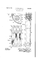
- ig. 1 is a view in elevation of an elevator guard gate provided with the curtain and its casing or housing embodying the invention.
- Fig. 2 is a view in vertical section of the casing parts shown in Fig. 1.
- Fig. 3 is a view in sectional plan of the casing and illustrating details of construction of the rollers and curtain shown in the foregoing figures.
- the reference numeral 25 designates an elevator structure
- the reference numeral 2,6 designates an ⁇ elevator guard gate of usual toggle-joint form.
- l provide ⁇ an auxiliary glardor lcurtain,277, bestnseen in Fig.
- the lower edge of the curtain preferably, as clearly shown in Fig. l, may be slightly above the fioor of the elevator and the upper edge of the curtain preferably is arranged considera-bly below the top of the elevator.
- the outer edge of the curtain is preferably bound by means of a strip 28, which strip is secured to the outer edge of the guard gate 26.
- the strip 28 is provided with a hand grip 29.
- the opposite parallel edge of the curtain is secured to the vertically disposed roller 30, best seen in Fig. 3.
- rlhis roller is of relatively large diameter and is contained within the casing or housing 3l which is fixed to the wall 32 of the elevator, see Fig. 2.
- the casing or housing is in the general formof the segment of a circle and is closed at its top by a cap 33 and at its bottom by a cap 34.
- Each of these caps is provided with a pair of lugs 36 and 37, in practice cast integral with the caps.
- These lugs forni bear ings for the roller 30 and the roller 38 which is relatively small in diameter and functions as a guide roller.
- the caps are removable and are secured to the casing or housing 3l 5 by means of screws 39, see bottom of Fig. 2.
- Each cap is provided with a flange 40 apertured at 4l for the reception of bolts 42 Whereby the casing with its caps may be secured to the eleva-tor Wall 32.
- the roller 30 is of the spring operated type so as to automatically Wind the curtain as the operator moves the guard gate to the right in Fig. 1, the curtain being guided by the small roller 38.' As the operator moves the guard gate and the curtain to the left in Fig. l, obviously the spring in unwinding tends to reduce tension so that the elevator operator does not have to exert any more eiort than he would naturally have to do in opening the guard gate, the advantages of which are apparent. It may be men tioned that the removable caps facilitate the ready insertion of the rollers and in case repairs are necessary, easy access may be had to the casing.
- a roller construction of the character stated comprising a pair of superimposed shell-like housing parts of segmental cross-section considered in plan, a cup-shaped segmental cap 80 for closing the top of said housing parts, a similar cap for closing the bottom of said housing parts, each of said caps being provided With a vertically disposed, integral, in- Wardly extended attachment lug and each of 85 said caps having an arcuate flange at its or Ward portion for seating the housing ends, a pair of lugs forming bearings formed integral With the inner faces of each of said caps to support a spring actuated roller, including an idler therein, and means for securing the housing ends to the arcuate flanges of said caps.
Landscapes
- Engineering & Computer Science (AREA)
- Structural Engineering (AREA)
- Architecture (AREA)
- Civil Engineering (AREA)
- Elevator Door Apparatuses (AREA)
Description
April 19, 1932 E. Hu'rcHlNsoN, JR
GUARD FOR ELEVATOR DOCRS Filed May 22, 1929 Afro/Mfr.
Patented pr. 19, 17932 UNITED STATES PATENT OFFICE GUARD Fon nLnvA'ron Doons Application led. May 22,
This invention, generally stated, relates to elevators as used in oflice buildings, apartment houses, business houses and the like, and has more especial relation to the equipment of the guard gate with additional protective means in the form of a curtain and in special casing parts for the curtain.
The leading object of the present invention is to provide an additional guard in the form of a curtain for the usual elevator guard gate and which may be moved simultaneously with the opening and closing of the guard gate, the curtain being preferably made of wire or wire mesh so that the elevator operators vision is not obscured by the curtain, and in the provision of a special casing or housing fixed to the elevator in which the curtain is contained when the guard gate is in folded position. v
A. further object of the present invention is to provide a small roller and a roller of large diameter within the casing or housing, whereby the curtain automatically may Wind or unwind with the closing and opening of the conventional guard and be concealed within said casing or housing when said gate is in folded position.
Other and further objects of the present invention reside in the provision of general details of construction and arrangement and combination of parts for attaining the re-V sults sought by the foregoing objects.
The invention consists of the novel constructions hereinafter described and finally claimed.
The nature, characteristic features and scope of the invention will be fully understood from the following description taken in connection with the accompanying drawin s forming part hereof, and in which:
ig. 1 is a view in elevation of an elevator guard gate provided with the curtain and its casing or housing embodying the invention.
Fig. 2 is a view in vertical section of the casing parts shown in Fig. 1.
Fig. 3 is a view in sectional plan of the casing and illustrating details of construction of the rollers and curtain shown in the foregoing figures.
For the purpose of illustrating my inven- 1-929.- serial No. 365,011.
tion l have-shown in the accompanying drawinos one form thereof which is at present preferred by me., since the same has been found in practice to give satisfactory and re* liable results, although it is to be 'understood that the various instrumentalities of which my invention consists can be variouslyV arranged and organized .and that my invention is not limited to the precise arrangement and organization of the instrumentalities as herein shown and described.
ln the drawings, the reference numeral 25 designates an elevator structure, and the reference numeral 2,6 designates an `elevator guard gate of usual toggle-joint form. Prac ticedictates that in the opening and closingV ofthe such guard gates, particularly when the elevator is in crowded condition, that umbrellas, canes and the like frequently 4become jammed within the toggle-joint parts oc Vthe gate, and not infrequently the'passengers 1fingers are pinched between the opening and `closing parts of the gate. In order to obviate this inconvenient and sometimes dangerous condition, l: provide `an auxiliary glardor lcurtain,277, bestnseen in Fig. 1, and which preferably is comprised of wire mesh or ythe like', `s ince the operators vision is not obscured by wire mesh. The lower edge of the curtain preferably, as clearly shown in Fig. l, may be slightly above the fioor of the elevator and the upper edge of the curtain preferably is arranged considera-bly below the top of the elevator. The outer edge of the curtain is preferably bound by means of a strip 28, which strip is secured to the outer edge of the guard gate 26. The strip 28 is provided with a hand grip 29. The opposite parallel edge of the curtain is secured to the vertically disposed roller 30, best seen in Fig. 3. rlhis roller is of relatively large diameter and is contained within the casing or housing 3l which is fixed to the wall 32 of the elevator, see Fig. 2. Considered in plan, see Fig. 3, the casing or housing is in the general formof the segment of a circle and is closed at its top by a cap 33 and at its bottom by a cap 34. Each of these caps is provided with a pair of lugs 36 and 37, in practice cast integral with the caps. These lugs forni bear ings for the roller 30 and the roller 38 which is relatively small in diameter and functions as a guide roller. The caps are removable and are secured to the casing or housing 3l 5 by means of screws 39, see bottom of Fig. 2.
Each cap is provided with a flange 40 apertured at 4l for the reception of bolts 42 Whereby the casing with its caps may be secured to the eleva-tor Wall 32. The roller 30 is of the spring operated type so as to automatically Wind the curtain as the operator moves the guard gate to the right in Fig. 1, the curtain being guided by the small roller 38.' As the operator moves the guard gate and the curtain to the left in Fig. l, obviously the spring in unwinding tends to reduce tension so that the elevator operator does not have to exert any more eiort than he would naturally have to do in opening the guard gate, the advantages of which are apparent. It may be men tioned that the removable caps facilitate the ready insertion of the rollers and in case repairs are necessary, easy access may be had to the casing. lVhat I claim is:
A roller construction of the character stated comprising a pair of superimposed shell-like housing parts of segmental cross-section considered in plan,a cup-shaped segmental cap 80 for closing the top of said housing parts, a similar cap for closing the bottom of said housing parts, each of said caps being provided With a vertically disposed, integral, in- Wardly extended attachment lug and each of 85 said caps having an arcuate flange at its or Ward portion for seating the housing ends, a pair of lugs forming bearings formed integral With the inner faces of each of said caps to support a spring actuated roller, including an idler therein, and means for securing the housing ends to the arcuate flanges of said caps.
EDWARD HUTCHINSON, JR.
Priority Applications (1)
| Application Number | Priority Date | Filing Date | Title |
|---|---|---|---|
| US365011A US1854936A (en) | 1929-05-22 | 1929-05-22 | Guard for elevator doors |
Applications Claiming Priority (1)
| Application Number | Priority Date | Filing Date | Title |
|---|---|---|---|
| US365011A US1854936A (en) | 1929-05-22 | 1929-05-22 | Guard for elevator doors |
Publications (1)
| Publication Number | Publication Date |
|---|---|
| US1854936A true US1854936A (en) | 1932-04-19 |
Family
ID=23437113
Family Applications (1)
| Application Number | Title | Priority Date | Filing Date |
|---|---|---|---|
| US365011A Expired - Lifetime US1854936A (en) | 1929-05-22 | 1929-05-22 | Guard for elevator doors |
Country Status (1)
| Country | Link |
|---|---|
| US (1) | US1854936A (en) |
Cited By (1)
| Publication number | Priority date | Publication date | Assignee | Title |
|---|---|---|---|---|
| US5427836A (en) * | 1993-08-20 | 1995-06-27 | Hall; Harry R. | Safety net |
-
1929
- 1929-05-22 US US365011A patent/US1854936A/en not_active Expired - Lifetime
Cited By (1)
| Publication number | Priority date | Publication date | Assignee | Title |
|---|---|---|---|---|
| US5427836A (en) * | 1993-08-20 | 1995-06-27 | Hall; Harry R. | Safety net |
Similar Documents
| Publication | Publication Date | Title |
|---|---|---|
| US4053007A (en) | Animal access door for screen doors | |
| US3869754A (en) | Bracket for a spring sash counterbalance | |
| US1946837A (en) | Doorcheck | |
| US1854936A (en) | Guard for elevator doors | |
| US3055044A (en) | Foot attachment for block and tackle type spring counterbalances | |
| US1821136A (en) | Hinge | |
| US3095922A (en) | Counterbalance and stop means for upwardly acting closures | |
| US2005198A (en) | Automobile door | |
| US2148059A (en) | Entrance cap | |
| CN209780705U (en) | Guardrail for door and window | |
| US1944321A (en) | Ventilator | |
| US1669990A (en) | Spring sash balance | |
| US1736784A (en) | Counter-weight mechanism | |
| US1707101A (en) | Revolving window or sash | |
| US3340649A (en) | Lightweight cellar doors | |
| US2090552A (en) | Window | |
| US1928423A (en) | Window regulator | |
| US2654118A (en) | Spring hinge | |
| US3192992A (en) | Overhead sectional door | |
| US758016A (en) | Automatic cover for awnings. | |
| NO823016L (en) | DEVICE FOR AA KEEP IT DOING THE MONKEY. | |
| US1716060A (en) | Guard for elevator doors | |
| US974564A (en) | Bank-protector. | |
| US2971790A (en) | Overhead door safety device | |
| DE565657C (en) | Garbage can elevator |