US1854934A - Method of grinding irregular shafts - Google Patents
Method of grinding irregular shafts Download PDFInfo
- Publication number
- US1854934A US1854934A US573623A US57362331A US1854934A US 1854934 A US1854934 A US 1854934A US 573623 A US573623 A US 573623A US 57362331 A US57362331 A US 57362331A US 1854934 A US1854934 A US 1854934A
- Authority
- US
- United States
- Prior art keywords
- shaft
- key
- cylindrical
- grinding
- irregular
- Prior art date
- Legal status (The legal status is an assumption and is not a legal conclusion. Google has not performed a legal analysis and makes no representation as to the accuracy of the status listed.)
- Expired - Lifetime
Links
- 238000000034 method Methods 0.000 title description 15
- 230000001788 irregular Effects 0.000 title description 14
- 241000287828 Gallus gallus Species 0.000 description 1
- 238000007689 inspection Methods 0.000 description 1
- 239000000463 material Substances 0.000 description 1
- 239000002184 metal Substances 0.000 description 1
- 230000004048 modification Effects 0.000 description 1
- 238000012986 modification Methods 0.000 description 1
Images
Classifications
-
- B—PERFORMING OPERATIONS; TRANSPORTING
- B24—GRINDING; POLISHING
- B24B—MACHINES, DEVICES, OR PROCESSES FOR GRINDING OR POLISHING; DRESSING OR CONDITIONING OF ABRADING SURFACES; FEEDING OF GRINDING, POLISHING, OR LAPPING AGENTS
- B24B5/00—Machines or devices designed for grinding surfaces of revolution on work, including those which also grind adjacent plane surfaces; Accessories therefor
-
- B—PERFORMING OPERATIONS; TRANSPORTING
- B24—GRINDING; POLISHING
- B24B—MACHINES, DEVICES, OR PROCESSES FOR GRINDING OR POLISHING; DRESSING OR CONDITIONING OF ABRADING SURFACES; FEEDING OF GRINDING, POLISHING, OR LAPPING AGENTS
- B24B1/00—Processes of grinding or polishing; Use of auxiliary equipment in connection with such processes
Definitions
- This invention relates to a method of grinding irregular shafts and particularly to a method of grinding cylindrical shafts which have flattened portions or key-ways formed therein, and has for its principal object the provision of a method for smoothly and accurately grinding cylindrical shafts having flattened portions or key-Ways formed there- 19
- a further object is the provision of a method for rapidly and economically grinding a shaftas described above.
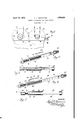
- Figure 1 illustrates the method of grinding cylinder shafts in a centerless grinder.
- Figure 2 is a perspective view of an irregular shaft, a key formed to fit in a slot in the shaft, and a cap formed to fit over one end of the shaft.
- Figure 3 is a plan view of the shaft, key and cap illustrated in Figure 2.
- Figure 4 is a perspective view of a slightly different form of irregular shaft and shows a key formed to fit in the slot in the shaft, and a cap adapted to cover the end of the shaft.
- Figure 5 is a plan view of the shaft, key
- Figures 2 and 3 illustrate an irregular shaft generally indicated at 5, having a cylindrical end portion 10, a reduced portion 12 and an intermediate cylindrical portion 14 having formed therein a longitudinal groove or keyway 15. Beyond the intermediate cylindrical portion, the shaft is provided with flat surfaces 16 and 17 and a transverse aperture 18 through the end thereof opposite the cylinbi drical portion 10.
- a shaft of this character would be impossible to grind by ordinary methods as the key-way breaks into the cylindrical surface and would cause the grinding wheels to rotate unevenly against the surface of the shaft, thereby producing a shaft having a surface far from accurately cylindrical. Also the flattened surfaces 16 and 17 make it impossible for the shaft to properly rotate on the holding mechanism of a centerless grinder.
- a key 20 is provided of such dimensions as to fit closely and accurately within the slot 15 and form a continuation of the cylindrical surface of the shaft over the slot.
- This key is made of material of the same hardness as the shaft and is slightly bent longitudinally so that it may be driven into the key-way 15 and wedged therein against accidental removal during the grinding process.
- a cap 22 which consists simply of a cylindrical cup which may be machined out of tubing or stamped out of sheet metal.
- This cup 22 has such an internal diameter and such a thickness that itwill fit securely upon the flattened end of the shaft and have an outer surface of substantially the same diameter as the outer surface of the cylinder portions 10 and 14.
- the shaft may then be insorted in a centerless grinder such as is illustrated in Figure l, and will progress through the grinder in the usual manner, all surfaces being smoothly and accurately ground to the desired dimensions.
- Figures 4 and 5 illustrate an irregular shaft somewhat similar to that illustrated in Figures 2 and 3 but differing in details suflicient- 1y to require a modification of the invention as applied to the shaft illustrated in Figures 2 and 3.
- the shaft illustrated in Figures 4 and 5 and generally indicated at 30 has a cylindrical end portion 35, a notch or groove portion 86, and an intermediate cylindrical portion 38 provided with a groove or key-way 40. Beyond the cylindrical portion 38, the shaft is provided with two flattened surfaces 42 and 433 and an additional flattened surface at right angles to the surfaces 42 and 4-3 and ertending from a point 46 adjacent the end of the shaft opposite the cylindrical portion into the cylindrical portion 38 as in-' dicated at i8.
- a key 50 which has a narrow portion 52 adapted to fit into the key-way a0 and wider portion 54; adapted to cover the portion 48 of the flattened surface and having a part y cylindrical upper surface adapted to form a continuation of the surface of the cylindrical portion 38.
- a cup shaped cylindrical cap 60 adapted to fit upon the flattened end of the shaft 30 and provide a surface having substantially the same dimensions as the surface of the portions 35 and 38.
- the portion of is formed to fit tightly into the ke -wa O and is slightly bent longitudinally so that it will wedge firmly in the key-way.
- the shaft may then be inserted in a cent-erless grinder as iilustrated l and will a the 1., i. ii
- the grinder used in this operation is of the centerless type and comprises a frame 65, a fixed journal bearing 66 and a slidable journal bearing 67.
- a shaft 68 which rotates in the fixed journal bearing 66 is a grinding wheel 69
- a shaft "2'0 which rotates in the slidable journal bearing 67 is a similar grinding wheel 72.
- the slidable journal bearing 67 is manually adjusted by means of a crank 78 connected with ascrew 7a.
- A. bed plate or block '55 is provided at each side of the grinding wheels 69 and 72. fhe shaft 5 to be ground is placed upon the block 75 and forced through between the rapidly rotating grinding wheels 69 and 72. During this operation, the distance between the two grinding wheels 69 and 72 is adjusted by means of the crank 73 until the shaft is ground to the exact dimensions required.
- the shaft rotates as it progresses between the grinding wheels, it will be seen that it is necessary that the shaft should have a cylindrical surface at both ends thereof so that the axis of the shaft will remain parallel to the axis of rotation of the grinding wheels, and it is also apparent that the cylindrical surface being ground must be substantially continuous, as any breaks in the continuity of the surface will cause the shaft to rotate irregularly between the grinding wheels whereby one portion of the shaft may be ground away more than another portion, thus producing an uneven surface on the shaft.
- a method of grinding an irregular cylindrical shaft having a key-way formed in the cylindricalportion thereof, and having a flattened end portion which comprises, inserting a key of approximately the same hardness of the shaft in said key-way, inserting a hollow cylindrical cap upon the flattened end of said shaft and working the shaft through a centerless grinder.
Landscapes
- Engineering & Computer Science (AREA)
- Mechanical Engineering (AREA)
- Grinding Of Cylindrical And Plane Surfaces (AREA)
Description
April 19, 1932. K. L. HERRMANN METHOD OF GRINDING IRREGULAR SHAFTS Filed Nov. '7, 1931 IN V EN TOR. A/2% ATTOR YS.
Patented Apr. 19, 1932 UNITED STATES PATENT OFFICE KARL L. HERRMANN, OF SOUTH BEND, INDIANA, ASSIGNOR TO THE BANTAM BALL BEARING COMPANY, OF SOUTH BEND, INDIANA, A CORPORATION OF INDIANA METHOD or GRINDING IRREGULAR srmrrs Application filed November 7, 1931.
This invention relates to a method of grinding irregular shafts and particularly to a method of grinding cylindrical shafts which have flattened portions or key-ways formed therein, and has for its principal object the provision of a method for smoothly and accurately grinding cylindrical shafts having flattened portions or key-Ways formed there- 19 A further object is the provision of a method for rapidly and economically grinding a shaftas described above.
Other objects and advantages will appear as the description proceeds.
The drawings illustrate two examples of such irregular shafts as are particularly adaptable to the use of the method of this invention, and also illustrate the method by which irregular shafts may be quickly, smoothly and accurately ground. The drawings, however, are not to be considered as limiting the invention, the scope of which is entirely commensurate with the scope of the co-pending claims.
In the drawings:
Figure 1 illustrates the method of grinding cylinder shafts in a centerless grinder.
Figure 2 is a perspective view of an irregular shaft, a key formed to fit in a slot in the shaft, and a cap formed to fit over one end of the shaft.
Figure 3 is a plan view of the shaft, key and cap illustrated in Figure 2.
Figure 4 is a perspective view of a slightly different form of irregular shaft and shows a key formed to fit in the slot in the shaft, and a cap adapted to cover the end of the shaft.
Figure 5 is a plan view of the shaft, key
. and cap illustrated in Figure 4. n) Referring to the drawings in detail, Figures 2 and 3 illustrate an irregular shaft generally indicated at 5, having a cylindrical end portion 10, a reduced portion 12 and an intermediate cylindrical portion 14 having formed therein a longitudinal groove or keyway 15. Beyond the intermediate cylindrical portion, the shaft is provided with flat surfaces 16 and 17 and a transverse aperture 18 through the end thereof opposite the cylinbi drical portion 10.
Serial No. 573,623.
From an inspection of this illustration, it will be observed that a shaft of this character would be impossible to grind by ordinary methods as the key-way breaks into the cylindrical surface and would cause the grinding wheels to rotate unevenly against the surface of the shaft, thereby producing a shaft having a surface far from accurately cylindrical. Also the flattened surfaces 16 and 17 make it impossible for the shaft to properly rotate on the holding mechanism of a centerless grinder. In order to overcome this difliculty and make it possible to grind the shaft in an ordinary commercial grinder, a key 20 is provided of such dimensions as to fit closely and accurately within the slot 15 and form a continuation of the cylindrical surface of the shaft over the slot. This key is made of material of the same hardness as the shaft and is slightly bent longitudinally so that it may be driven into the key-way 15 and wedged therein against accidental removal during the grinding process.
For the flattened end of the shaft, there is provided a cap 22 which consists simply of a cylindrical cup which may be machined out of tubing or stamped out of sheet metal. This cup 22 has such an internal diameter and such a thickness that itwill fit securely upon the flattened end of the shaft and have an outer surface of substantially the same diameter as the outer surface of the cylinder portions 10 and 14.
l Vhen the key 20 has been inserted in the key-way 15 and the cap 22 placed upon the end of the shaft, the shaft may then be insorted in a centerless grinder such as is illustrated in Figure l, and will progress through the grinder in the usual manner, all surfaces being smoothly and accurately ground to the desired dimensions.
Figures 4 and 5 illustrate an irregular shaft somewhat similar to that illustrated in Figures 2 and 3 but differing in details suflicient- 1y to require a modification of the invention as applied to the shaft illustrated in Figures 2 and 3. v
.The shaft illustrated in Figures 4 and 5 and generally indicated at 30 has a cylindrical end portion 35, a notch or groove portion 86, and an intermediate cylindrical portion 38 provided with a groove or key-way 40. Beyond the cylindrical portion 38, the shaft is provided with two flattened surfaces 42 and 433 and an additional flattened surface at right angles to the surfaces 42 and 4-3 and ertending from a point 46 adjacent the end of the shaft opposite the cylindrical portion into the cylindrical portion 38 as in-' dicated at i8.
In order to round out the cylindrical portion 38, l have provided a key 50 which has a narrow portion 52 adapted to fit into the key-way a0 and wider portion 54; adapted to cover the portion 48 of the flattened surface and having a part y cylindrical upper surface adapted to form a continuation of the surface of the cylindrical portion 38. In this instance there is also provided a cup shaped cylindrical cap 60 adapted to fit upon the flattened end of the shaft 30 and provide a surface having substantially the same dimensions as the surface of the portions 35 and 38.
The portion of is formed to fit tightly into the ke -wa O and is slightly bent longitudinally so that it will wedge firmly in the key-way. When the key 50 and the cap have been inserted on the shaft 30, the shaft may then be inserted in a cent-erless grinder as iilustrated l and will a the 1., i. ii
in- Figure l progress through the grinder in the usuai manner.
Referring to Figure 1, it will be observed that the grinder used in this operation is of the centerless type and comprises a frame 65, a fixed journal bearing 66 and a slidable journal bearing 67. Mounted on a shaft 68 which rotates in the fixed journal bearing 66 is a grinding wheel 69, and mounted on a shaft "2'0 which rotates in the slidable journal bearing 67 is a similar grinding wheel 72. The slidable journal bearing 67 is manually adjusted by means of a crank 78 connected with ascrew 7a.
A. bed plate or block '55 is provided at each side of the grinding wheels 69 and 72. fhe shaft 5 to be ground is placed upon the block 75 and forced through between the rapidly rotating grinding wheels 69 and 72. During this operation, the distance between the two grinding wheels 69 and 72 is adjusted by means of the crank 73 until the shaft is ground to the exact dimensions required.
Owing to the fact that the shaft rotates as it progresses between the grinding wheels, it will be seen that it is necessary that the shaft should have a cylindrical surface at both ends thereof so that the axis of the shaft will remain parallel to the axis of rotation of the grinding wheels, and it is also apparent that the cylindrical surface being ground must be substantially continuous, as any breaks in the continuity of the surface will cause the shaft to rotate irregularly between the grinding wheels whereby one portion of the shaft may be ground away more than another portion, thus producing an uneven surface on the shaft.
Having now described my invention and the principal objects and advantages thereof so that oth rs skilled in the art may clearly understand the same, what I desire to secure by Letters Patent is as follows:
1. The method of grinding cylindrical surfaces on an irregular shaft which comprises, rounding out the irregular portions of the shaft by means of keys of approximately the same hardness as the shaft firmly fixed to the shaft to cover said irregularities and then working the shaft through a centerless grinder.
2. A method of grinding an irregular cylindrical shaft having a key-way formed in the cylindricalportion thereof, and having a flattened end portion which comprises, inserting a key of approximately the same hardness of the shaft in said key-way, inserting a hollow cylindrical cap upon the flattened end of said shaft and working the shaft through a centerless grinder.
if method of grinding an irregular cylindrical shaft having a key-way and a fiattened portion in the cylindrical portion thereof, and having a flattened end portion which comprises, forming a key having a narrow portion to fit in said key-way and a wide .portion with a partly cylindrical surface to cov-- er said flattened portion and forming a continuation of the surface of said cylindrical portion, inserting a hollow cylindrical cap upon. the flattened end of said shaft and workin g the shaft through a centerless grinder.
Signed by me at South Bend, Indiana, this i day of November, 1981.
KARL L, HERRMANN.
Priority Applications (1)
| Application Number | Priority Date | Filing Date | Title |
|---|---|---|---|
| US573623A US1854934A (en) | 1931-11-07 | 1931-11-07 | Method of grinding irregular shafts |
Applications Claiming Priority (1)
| Application Number | Priority Date | Filing Date | Title |
|---|---|---|---|
| US573623A US1854934A (en) | 1931-11-07 | 1931-11-07 | Method of grinding irregular shafts |
Publications (1)
| Publication Number | Publication Date |
|---|---|
| US1854934A true US1854934A (en) | 1932-04-19 |
Family
ID=24292737
Family Applications (1)
| Application Number | Title | Priority Date | Filing Date |
|---|---|---|---|
| US573623A Expired - Lifetime US1854934A (en) | 1931-11-07 | 1931-11-07 | Method of grinding irregular shafts |
Country Status (1)
| Country | Link |
|---|---|
| US (1) | US1854934A (en) |
-
1931
- 1931-11-07 US US573623A patent/US1854934A/en not_active Expired - Lifetime
Similar Documents
| Publication | Publication Date | Title |
|---|---|---|
| US2324083A (en) | Method of making bearings | |
| US1854934A (en) | Method of grinding irregular shafts | |
| US1907897A (en) | Method of making spline shafts | |
| US3279234A (en) | Plate rolling machine | |
| US2279216A (en) | Gear and pinion | |
| US1847848A (en) | Method of making worm gears | |
| US1722494A (en) | Art of forming matchable bearings | |
| US2129257A (en) | Process of making thrust rollers for fluid meters | |
| US2428301A (en) | Method of producing forming rolls for use in rolling mills and the like | |
| US2167311A (en) | Method of abrading crankshafts | |
| CN102744272A (en) | Material blocking guide plate for wedge-shaped cross rolling mill | |
| US3106018A (en) | Axle for glass cutters | |
| US1636670A (en) | Method of making segmental laminated gears | |
| US1918020A (en) | Brake shoe burnisher | |
| US2955638A (en) | Forming and pressure dies for pipe-bending machines | |
| US1722492A (en) | Matchable bearing | |
| US73467A (en) | Samuel j | |
| US1784463A (en) | Process of making cylindrical rollers | |
| GB467835A (en) | Improvements in glass grinding tools | |
| US2717625A (en) | Apparatus for producing edge compression stresses in metal strips | |
| US1840641A (en) | Metal woking process | |
| US2192804A (en) | Sanding drum | |
| US1632255A (en) | Rotary percussion implement | |
| US1197204A (en) | Means for restraining a pulley or wheel on its journal. | |
| US2130409A (en) | Abrading roller |