US1854928A - Friction device for motion picture projection machines - Google Patents
Friction device for motion picture projection machines Download PDFInfo
- Publication number
- US1854928A US1854928A US356997A US35699729A US1854928A US 1854928 A US1854928 A US 1854928A US 356997 A US356997 A US 356997A US 35699729 A US35699729 A US 35699729A US 1854928 A US1854928 A US 1854928A
- Authority
- US
- United States
- Prior art keywords
- reel
- shaft
- friction
- bearing
- housing
- Prior art date
- Legal status (The legal status is an assumption and is not a legal conclusion. Google has not performed a legal analysis and makes no representation as to the accuracy of the status listed.)
- Expired - Lifetime
Links
- 239000000463 material Substances 0.000 description 10
- 230000001276 controlling effect Effects 0.000 description 3
- 230000003247 decreasing effect Effects 0.000 description 3
- 230000007246 mechanism Effects 0.000 description 3
- 230000000979 retarding effect Effects 0.000 description 3
- 230000009471 action Effects 0.000 description 2
- 230000001419 dependent effect Effects 0.000 description 2
- 239000004519 grease Substances 0.000 description 2
- 230000001105 regulatory effect Effects 0.000 description 2
- 210000003813 thumb Anatomy 0.000 description 2
- XRMDCWJNPDVAFI-UHFFFAOYSA-N 2,2,6,6-tetramethyl-1-oxopiperidin-1-ium-4-ol Chemical compound CC1(C)CC(O)CC(C)(C)[N+]1=O XRMDCWJNPDVAFI-UHFFFAOYSA-N 0.000 description 1
- 235000010627 Phaseolus vulgaris Nutrition 0.000 description 1
- 244000046052 Phaseolus vulgaris Species 0.000 description 1
- 238000010276 construction Methods 0.000 description 1
- 230000007423 decrease Effects 0.000 description 1
- 239000011521 glass Substances 0.000 description 1
- 230000008520 organization Effects 0.000 description 1
- 230000004044 response Effects 0.000 description 1
- 238000006467 substitution reaction Methods 0.000 description 1
- 238000004804 winding Methods 0.000 description 1
Images

Classifications
-
- G—PHYSICS
- G03—PHOTOGRAPHY; CINEMATOGRAPHY; ANALOGOUS TECHNIQUES USING WAVES OTHER THAN OPTICAL WAVES; ELECTROGRAPHY; HOLOGRAPHY
- G03B—APPARATUS OR ARRANGEMENTS FOR TAKING PHOTOGRAPHS OR FOR PROJECTING OR VIEWING THEM; APPARATUS OR ARRANGEMENTS EMPLOYING ANALOGOUS TECHNIQUES USING WAVES OTHER THAN OPTICAL WAVES; ACCESSORIES THEREFOR
- G03B21/00—Projectors or projection-type viewers; Accessories therefor
- G03B21/14—Details
- G03B21/32—Details specially adapted for motion-picture projection
- G03B21/43—Driving mechanisms
Definitions
- This invention relates to reeling devices, and more particularly, to a frictional takeup mechanism adapted to apply a substantially uniform tension to the material on a reel.
- the invention relates more specifically to a reel for a motion picture projection machine in which the film is fed at a constant speed and at a substantially uniform tension.
- the invention may, however, be applied to other types of reels and winding apparatus as will be apparent toa person skilled in the art.
- An object of the invention is to provide a frictional device which is capable of frictionally opposing the action of thereel with a force dependent upon the weight of the material carried thereon.
- Another object is to provide a frictional reeling device which is capable of maintaining the material supported by the reel at a substantially uniform tension regardless of the diameter of the material so carried.
- a further object of the invention is to so vary the frictional force applied to a reel with respect to the speed of rotation of the reel andthe, diameter of the material carried thereon that a substantially uniform tension is applied to said material in reeling and unreeling.
- Still another object is to provide a. variable frictional retarding ,device for a reel and means for controlling-the friction thereof for causing said device to act as a brake.
- a feature of the invention 18 a frictional clutch for opposing the rotation of a reel with a force which is determinedby the weight of the material onthe reel and the speed of rotation thereof.
- Another feature of the invention is an adjustable bearing for a reel by meansof which the friction exerted upon said reel may be controlled.
- the invention also consists in certain new andj original features of construction and combinations of parts hereinafter set forth and claimed.
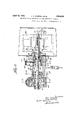
- Fig. 4 is a longitudinal sectional view of the frictional take-up device applied to the shaft of the upper film reel;
- Fig. 5 is a section taken on the line 55 of Fig. 4;
- Fig. 6 is a section taken on the line 6-6 of Fig. 4.
- Fig. 7 is a section taken on the line 7-7 of Fig. 4.
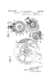
- FIG. 1 a motion picture projection machine having a projection head 10 (Figs. 1 and 2), a housing 11 and'an upper film magazine 12.
- projection head 10 Figs. 1 and 2
- FIG. 2 The particular form of projection head forms no part of the present invention and has not been set forth in detail.
- Film magazine 12 is supported from housing 11 in any suitable manner and includes a door 13 which is hingedly supported as by hinge 14 (Fig. 2).
- a glass window '15 may be included'in said door to allow the operator to obs-ervethe amount of film on the reel, atany particular instant.
- a suitable latch 16 may be provided for securing door 13 in closed .position.
- the reel 20 which may be of any suitable form, is mounted upon shaft 21 which is rotatably secured in housing 11 by an adjustable bearing.
- Said bean ing comprises a slidable sleeve 22 carrying a cupped flange 23 which is mounted on shaft 21 and keyed to a suitable groove 24 therein as by adjustable key 25.
- .Cupped flange 23 carries the inner ball race 26 with which balls 27 are in contact.
- Outer ball race 30 is carried in sleeve 31 against shoulder 32 thereof and is secured by a tubular member 33 which is threaded into said sleeve 31 and bears against said ball race 30.
- Sleeve 33 is provided with a circular groove 35 in which thumb screw 36 is adapted to seat for locking said tubular member in position.
- Thumb screw 36 extends through an elongated slot 37 in housing 11 and serves as a handle for longitudinally adj usting the bearing with respect to both shaft 21 and said housing.
- a grease cup 40 is positioned in housing 11 in communication with a groove 41 in sleeve 31. Oil is applied to the hearing from grease cup 40 through groove 41 and bore 42 and is discharged around shoulder 43 of sleeve 31, thence through groove 44 and bore 45. Pin 46 is secured in sleeve 31 and is adapted to slide in groove 44 in accordance with the longitudinal position of said bear- .ing. Oil guard 50 is pinned to shaft 21, as by pin 51, and is provided with oil threads 52 which prevent oil from creeping along the surface of shaft 21 into the film magazine. Oil shield 53 is secured to the wall of said magazine and extends into a position closely adjacent oil guard 50 for preventing a direct passage of oil into the film magazine.
- Oil guard 50 is also provided with suitable holes 54 which are adapted to receive pins 55 carried by the reel for rotatably securing the reel on shaft 21.
- the reel is secured on shaft 21 by a reel lock 56 which is pivotally mounted as by pin 57 to the end of said shaft and bears against a spring pressed detent 58 which is secured in a suitable bore therein.
- Shaft 59 of reel block 56 is so formed as to exert a. cam action against said detent whereby it is securely held either in extended or in looking position.
- Brake housing 60 is formed with a hub member 61 which is in sliding engagement with a bore in housing 11. Said hub is provided with a circular groove62 which is adapted to contact'with a deformed bolt 63 by means of which the brake housing 60 is secured in housing 11.
- Bolt 63 (Fig. 6) is.
- a thrust bearing comprising a block slightly smaller than the interior of brake housing 60 and is adapted to rotate freely therein.
- Block 72 is provided with an elongated slot 7 6through which shaft 21 extends whereby vertical movement of said shaft is permitted within a limited range.
- the brake mechanism comprises friction blocks which are mounted on' yoke 81 and extend through suitable apertures in brake I housing 60 into contact with brake drum 73.
- Yoke 81 is carried on threaded bolt 82 which is secured in said brake housing and may be adjusted with respect "thereto by means of threaded'nut 83 which is carried on said bolt and lock nut 84 which cooperates therewith.
- the elevation of friction members 80 with respect to the brake housing may be controlled by suitable adjustment of yoke 81.
- the weight of the reel causes shaft 21 to pivot about the slidable bearing as a fulcrum, thereby tending to urge brake drum 73 into contact with friction blocks 80.
- the amount of friction which is exerted by said blocks is determined by the weight of the material on reel 20. Hence, the maximum amount of friction will beapplied when a full reel is positioned on shaft 21 and this friction will be progressively decreased as the film is unwoundfi;
- the amount of friction applied to the brake drum may be manually regulated by va g the elevation of friction blocks 80 as a ove pointed out and may also be controlled by longitudinally varying the position of the slidable b aring with res ect to shaft 71. .
- the length of the lever arm supporting the reel isincreased and the length of the arm between the bearing and the brake drum is decreased.
- a iven weight of reel accordingly causes the brake drum to bear against friction blocks 80 with a greater force.
- the friction device may be made to operate as a brake for stopping the operation of the reel when the bearing is adjusted to its extreme position. This feature may be utilized when it is desired to quickly stop the reel for any reason, such as breakage of the film.
- the oiling means above described permits applied to the 1m magazine where it could such manner that a substantiall come in contact with the projection film. 5.
- the invention has een shown as applied to the upper film magazine of a projection machine, but it is not limited thereto. It may also be applied to the lower film magazine or to other reeling devices as will be apparent to a person skilled in the art.
- a reeling-device a rotatable shaft a retarding means and a reel carried on said shaft, a bearing for said shaft positioned between said retardin device and said reel, said bearing being adapted to permit pivotal movement of said shaft about said bearing as an" axis in response to the weight of material on: said reel, and means for longitudinally moving said bearing to vary the position of said axis with respect to said retarding device and said reel.
- a shaft for supporting a reel, a bearing intermediate the ends of said shaft for rotatably mounting the same and for permitting pivotal movement thereof abouta horizontal axis, a brake drum and a reel carried by said shaft at opposite sides of said bearing, a friction device, and means whereby the weight-of said reel causes pivotal movement of saidshaft about said axis, said pivotal movement altering the transverse position of said brake drum with respect to said friction device, whereby the amount of friction therebetween is controlled.
- a shaft for supporting a reel for supporting a reel, a bearing for rotatably mounting saidshaft and for permitting pivotal movement thereof about a horizontal axis, a brake drum carried by said shaft, a friction device carried by said brake drum and means whereby the weight of said reel causes pivotal movement of said shaft for bringing said brake drum into engagement with said friction device, whereby the rotation of said shaft is opposed, and means for longitudinally moving said bearing for varying the ratio between the weight of said reel and the pressure exerted by said brake drum.
- a bearing for supporting said shaft in said housing comprising a sleevefcarried by said shaft and slidable thereon, a second sleeve mounted in said housing and slidable therein, a handle associated with said second sleeve and extending through a slot insaid housing foradjusting the longitudinal posi-.
- an oil guard mounted on said shaft for limiting'the longitudinal movement of oil
- oiling means comprising a slot in said second sleeve communicating with said bearing, a brake drum mounted on said a shaft, friction members carried by said hous- -ing, and means for varying the position of said members with respect to said brake drum for adjusting the friction thereof, said shaft being adapted to pivot vertically about said bearing whereby the weight of material supported thereby is caused to bring said brake drum into engagement with said friction members.
- a rotatable shaft adapted to support a reel, means for pivotally mounting said shaftfor movement about a fulcrum intermediate the ends thereof,
Landscapes
- Physics & Mathematics (AREA)
- General Physics & Mathematics (AREA)
- Storage Of Web-Like Or Filamentary Materials (AREA)
Description
April 19,1932. 4 s FRAPPIE'R ET AL 1,854,928
FRICTION DEVICE FOR MOTION PICTURE PROJECTION MACHINES Filed April 22, 1929 3 Sheets-Sheet -l i W I @W Q C).
[wa/a ZMOUNQ 3513/56 a t tome;
April 19, 1932.- s; FRAPPIER ET AL 1,854,923
FRICTION DEVICE FOR MOTION PICTURE PROJECTION MACHINES Filed April 22, 1929 3 Sheets-Sheet 2 L. s. FRAPPIER ET AL April 19, 1932.
FRICTION DEVICE FOR MOTION PICTURE PROJECTION MACHINES 3 Sheets-Sheet 3 Filed April 22, 1929 1. W Xmfi ENE @S & mm F 7 NR I Q G ll EEmwrl kllk IIIQI T I NMM H W. MILH S I Z i K I I i J N3. 5 -IFILY w s% I Zinvcmfow low: 5'. Fro J fryer/M506 Patented Apr. 19, 1932 uni-m STATES PATENT OFFICE murssmon raarrma am) EWALD nonoxme, or BROOKLYN, new YORK, nssren'oas 'ro mraannrronnr. raomc'rnn conroan'rron, or new YORK, n. Y., A oonrom- T101?" OF DELAWARE FRICTION DEVICE FOR MOTION PICTURE PROJECTION MACHINES Application filed 'April 22, 1929. Serial No. 356,987.
This invention relates to reeling devices, and more particularly, to a frictional takeup mechanism adapted to apply a substantially uniform tension to the material on a reel.
The invention relates more specifically to a reel for a motion picture projection machine in which the film is fed at a constant speed and at a substantially uniform tension. The invention may, however, be applied to other types of reels and winding apparatus as will be apparent toa person skilled in the art.
An object of the invention is to provide a frictional device which is capable of frictionally opposing the action of thereel with a force dependent upon the weight of the material carried thereon.
Another object is to provide a frictional reeling device which is capable of maintaining the material supported by the reel at a substantially uniform tension regardless of the diameter of the material so carried.
A further object of the invention is to so vary the frictional force applied to a reel with respect to the speed of rotation of the reel andthe, diameter of the material carried thereon that a substantially uniform tension is applied to said material in reeling and unreeling. V
Still another object is to provide a. variable frictional retarding ,device for a reel and means for controlling-the friction thereof for causing said device to act as a brake.
A feature of the invention 18 a frictional clutch for opposing the rotation of a reel with a force which is determinedby the weight of the material onthe reel and the speed of rotation thereof. O
Another feature of the invention is an adjustable bearing for a reel by meansof which the friction exerted upon said reel may be controlled.
Other objects and features of the invention will be apparent as the natureof the invention is more fully disclosed. I I
The invention also consists in certain new andj original features of construction and combinations of parts hereinafter set forth and claimed.
Although the novel fe tures which are believed to be characteristic of this invention will be 'partlcularly pointed out in the claims appended hereto, the invention itself, as to its 1 objects and advantages, the mode of its operation and the manner of its organization may be better understood by referring to the following description taken in connection with the accompanying drawings forming a.
the film magazine;
Fig. 4 is a longitudinal sectional view of the frictional take-up device applied to the shaft of the upper film reel;
Fig. 5 is a section taken on the line 55 of Fig. 4;
Fig. 6 is a section taken on the line 6-6 of Fig. 4; and
Fig. 7 is a section taken on the line 7-7 of Fig. 4.
Like reference characters denote like parts in the several figures of the drawings.
In the following description and in the claims parts will be identified by specific names for convenience, but. they are intended to be as generic in their application to similar parts as the art will permit.
Referring to the drawings more in detail, the invention is' shown specifically as applied to a motion picture projection machine having a projection head 10 (Figs. 1 and 2), a housing 11 and'an upper film magazine 12. The particular form of projection head forms no part of the present invention and has not been set forth in detail. Film magazine 12 is supported from housing 11 in any suitable manner and includes a door 13 which is hingedly supported as by hinge 14 (Fig. 2). A glass window '15 may be included'in said door to allow the operator to obs-ervethe amount of film on the reel, atany particular instant. A suitable latch 16 may be provided for securing door 13 in closed .position.
' Referring to Fig. 4-, the reel 20, which may be of any suitable form, is mounted upon shaft 21 which is rotatably secured in housing 11 by an adjustable bearing. Said bean ing comprises a slidable sleeve 22 carrying a cupped flange 23 which is mounted on shaft 21 and keyed to a suitable groove 24 therein as by adjustable key 25. .Cupped flange 23 carries the inner ball race 26 with which balls 27 are in contact.
A grease cup 40 is positioned in housing 11 in communication with a groove 41 in sleeve 31. Oil is applied to the hearing from grease cup 40 through groove 41 and bore 42 and is discharged around shoulder 43 of sleeve 31, thence through groove 44 and bore 45. Pin 46 is secured in sleeve 31 and is adapted to slide in groove 44 in accordance with the longitudinal position of said bear- .ing. Oil guard 50 is pinned to shaft 21, as by pin 51, and is provided with oil threads 52 which prevent oil from creeping along the surface of shaft 21 into the film magazine. Oil shield 53 is secured to the wall of said magazine and extends into a position closely adjacent oil guard 50 for preventing a direct passage of oil into the film magazine.
Brake housing 60 is formed with a hub member 61 which is in sliding engagement with a bore in housing 11. Said hub is provided with a circular groove62 which is adapted to contact'with a deformed bolt 63 by means of which the brake housing 60 is secured in housing 11. Bolt 63 (Fig. 6) is.
provided with a curved recess 64 which is adapted to be-drawn against hub 61 for looking the brake housing in position. Slot 65 communicates with groove 62 and permits the brake housing to be withdrawn when said zlot is rotated into a position adjacent bolt Longitudinal movement of shaft 21 is prevented by a thrust bearing comprising a block slightly smaller than the interior of brake housing 60 and is adapted to rotate freely therein. Block 72 is provided with an elongated slot 7 6through which shaft 21 extends whereby vertical movement of said shaft is permitted within a limited range.
The brake mechanism comprises friction blocks which are mounted on' yoke 81 and extend through suitable apertures in brake I housing 60 into contact with brake drum 73.
It is to be noted that the weight of the reel causes shaft 21 to pivot about the slidable bearing as a fulcrum, thereby tending to urge brake drum 73 into contact with friction blocks 80. The amount of friction which is exerted by said blocks is determined by the weight of the material on reel 20. Hence, the maximum amount of friction will beapplied when a full reel is positioned on shaft 21 and this friction will be progressively decreased as the film is unwoundfi;
- Since the film travels at a constant speed the reel must rotate at a speed which is dependent upon the diameter of the film which is carried thereon. This is accomplished in accordance with the present invention by decreasing the friction on brake drum 73 as the weight of the reel decreases thereby permitting the reel to rotate at a faster speed.
The amount of friction applied to the brake drum may be manually regulated by va g the elevation of friction blocks 80 as a ove pointed out and may also be controlled by longitudinally varying the position of the slidable b aring with res ect to shaft 71. .When said bearing is move toward the brake drum the length of the lever arm supporting the reel isincreased and the length of the arm between the bearing and the brake drum is decreased. A iven weight of reel accordingly causes the brake drum to bear against friction blocks 80 with a greater force. By suitably designing the above elements the friction device may be made to operate as a brake for stopping the operation of the reel when the bearing is adjusted to its extreme position. This feature may be utilized when it is desired to quickly stop the reel for any reason, such as breakage of the film.
The oiling means above described permits applied to the 1m magazine where it could such manner that a substantiall come in contact with the projection film. 5.
It is to be noted that in the mechanism above described, not only is the friction applied to the reel regulated automatically in constant tension is maintained on the film, ut a readily accessible manual adjustment is provided whereby the apparatus may be readily adapted to any particular t e or size of reel.
The invention has een shown as applied to the upper film magazine of a projection machine, but it is not limited thereto. It mayalso be applied to the lower film magazine or to other reeling devices as will be apparent to a person skilled in the art.
While certain novel features of'the invention have been shown'and described and are pointed out in the annexed claims, it will be understood that various omissions, substitutions and changes'in the forms and details of the device illustrated and in its operation maye be made by those skilled in the art without departing from the spirit of the invention.
What is claimed is: 1. In a reeling-device, a rotatable shaft a retarding means and a reel carried on said shaft, a bearing for said shaft positioned between said retardin device and said reel, said bearing being adapted to permit pivotal movement of said shaft about said bearing as an" axis in response to the weight of material on: said reel, and means for longitudinally moving said bearing to vary the position of said axis with respect to said retarding device and said reel.
2. In a reeling device, a shaft for supporting a reel, a bearing intermediate the ends of said shaft for rotatably mounting the same and for permitting pivotal movement thereof abouta horizontal axis, a brake drum and a reel carried by said shaft at opposite sides of said bearing, a friction device, and means whereby the weight-of said reel causes pivotal movement of saidshaft about said axis, said pivotal movement altering the transverse position of said brake drum with respect to said friction device, whereby the amount of friction therebetween is controlled.
' 3. In a reeling device, a shaft for supporting a reel, a bearing for rotatably mounting saidshaft and for permitting pivotal movement thereof about a horizontal axis, a brake drum carried by said shaft, a friction device carried by said brake drum and means whereby the weight of said reel causes pivotal movement of said shaft for bringing said brake drum into engagement with said friction device, whereby the rotation of said shaft is opposed, and means for longitudinally moving said bearing for varying the ratio between the weight of said reel and the pressure exerted by said brake drum.
4. In combination with a housing, a bearingslidably mounted therein,.a shaft rotate;
bly mounted in said bearingfand extending on opposite sides thereof, means for "supporting a reel on oneend of; said shaft,} a brake drum mountedon the other fendv thereofia frlction elementocarried, by said" housing in a position to coopenate with said'brakedi'um for opposing rotation of said shaft, and means for varying the position of saidbearing whereby the effective lever arms between said bearing and said reel and said brake drum respectively may be adjusted.
5. In combination with a housing, a bearing slidably mounted therein, ashaftrOtatably mounted in .said bearing and extending on opposite sides thereof, means fonsupporting a reel on one end of said shaft, a brake drum mounted on the other..end thereof, a
friction device carried by said housing in a position to cooperate with said brake drum for controlling rotation of said shaft, and
means-for varying the position'of said friction deVlCQ for controlling the amount of said frlction, and means for varying the position of said bearing whereby the effective lever 'drum' associated with said shaft, means responsive to the weight of said reel for exerting frictional force against said brake drum,
ind means for adjusting the amount of said orce. i
I x I 7. In combination with a rotatable shaft, a
housing, a bearing for supporting said shaft in said housing comprising a sleevefcarried by said shaft and slidable thereon, a second sleeve mounted in said housing and slidable therein, a handle associated with said second sleeve and extending through a slot insaid housing foradjusting the longitudinal posi-. tion of said bearing, an oil guard mounted on said shaft for limiting'the longitudinal movement of oil, oiling means comprising a slot in said second sleeve communicating with said bearing, a brake drum mounted on said a shaft, friction members carried by said hous- -ing, and means for varying the position of said members with respect to said brake drum for adjusting the friction thereof, said shaft being adapted to pivot vertically about said bearing whereby the weight of material supported thereby is caused to bring said brake drum into engagement with said friction members.
8. In a reeling device, a rotatable shaft adapted to support a reel, means for pivotally mounting said shaftfor movement about a fulcrum intermediate the ends thereof,
means whereby the weight of mateiial on said shaft causes said pivotal movement, a. vfriction element and a reel carried by said shaft on opposite sides of said mounting, means whereby pivotal movement of said shaft causes movement of said friction element transverse to the axis thereof, and means for frictionally controlling the rotation of said shaft in accordance with the transverse position of said friction element.
LOUIS SIMON FRAPPIER.
EWALD BOECKING. Y
Priority Applications (1)
| Application Number | Priority Date | Filing Date | Title |
|---|---|---|---|
| US356997A US1854928A (en) | 1929-04-22 | 1929-04-22 | Friction device for motion picture projection machines |
Applications Claiming Priority (1)
| Application Number | Priority Date | Filing Date | Title |
|---|---|---|---|
| US356997A US1854928A (en) | 1929-04-22 | 1929-04-22 | Friction device for motion picture projection machines |
Publications (1)
| Publication Number | Publication Date |
|---|---|
| US1854928A true US1854928A (en) | 1932-04-19 |
Family
ID=23403870
Family Applications (1)
| Application Number | Title | Priority Date | Filing Date |
|---|---|---|---|
| US356997A Expired - Lifetime US1854928A (en) | 1929-04-22 | 1929-04-22 | Friction device for motion picture projection machines |
Country Status (1)
| Country | Link |
|---|---|
| US (1) | US1854928A (en) |
Cited By (1)
| Publication number | Priority date | Publication date | Assignee | Title |
|---|---|---|---|---|
| US2571061A (en) * | 1947-05-16 | 1951-10-09 | Western Electric Co | Reel spindle |
-
1929
- 1929-04-22 US US356997A patent/US1854928A/en not_active Expired - Lifetime
Cited By (1)
| Publication number | Priority date | Publication date | Assignee | Title |
|---|---|---|---|---|
| US2571061A (en) * | 1947-05-16 | 1951-10-09 | Western Electric Co | Reel spindle |
Similar Documents
| Publication | Publication Date | Title |
|---|---|---|
| US2766945A (en) | Wire winding apparatus with constant tension | |
| US2723776A (en) | Cover support device | |
| US1854928A (en) | Friction device for motion picture projection machines | |
| US2978195A (en) | Means for controlling filament tension in winding apparatus | |
| US2419808A (en) | Wire tensioning device for coil winding machines | |
| US2581306A (en) | Stationary spool reel | |
| US2111012A (en) | Camera support | |
| US1850755A (en) | Take-up device | |
| US1418706A (en) | Reeling device | |
| US1654800A (en) | Film-take-up device | |
| US2346756A (en) | Paper reel brake | |
| US2535584A (en) | Fishing reel | |
| US3021134A (en) | Adjustable roller hanger for paper folding machines | |
| US3139243A (en) | Tension compensating control device | |
| US1912013A (en) | Tensioning device | |
| US2599189A (en) | Line pickup device for fishing reel having nonrotary drums | |
| US1957164A (en) | Pad roller mounting | |
| US3239162A (en) | Friction drive adjustment for a fishing reel | |
| US2733876A (en) | Web tenfskbsr mechanism | |
| US3804348A (en) | Regulated windup apparatus | |
| US2243678A (en) | Yarn guide control for winding machines | |
| US2173996A (en) | Film-guiding mechanism | |
| US1857780A (en) | Friction drive for motion picture machines | |
| US2553374A (en) | Tension device | |
| US2836375A (en) | Fishing reel |