US1854919A - Electric switch - Google Patents
Electric switch Download PDFInfo
- Publication number
- US1854919A US1854919A US155369A US15536926A US1854919A US 1854919 A US1854919 A US 1854919A US 155369 A US155369 A US 155369A US 15536926 A US15536926 A US 15536926A US 1854919 A US1854919 A US 1854919A
- Authority
- US
- United States
- Prior art keywords
- switch
- pin
- conductor
- plate
- fingers
- Prior art date
- Legal status (The legal status is an assumption and is not a legal conclusion. Google has not performed a legal analysis and makes no representation as to the accuracy of the status listed.)
- Expired - Lifetime
Links
- 210000003811 finger Anatomy 0.000 description 27
- 239000004020 conductor Substances 0.000 description 26
- 230000003137 locomotive effect Effects 0.000 description 2
- 101100334009 Caenorhabditis elegans rib-2 gene Proteins 0.000 description 1
- 239000000945 filler Substances 0.000 description 1
- 239000011810 insulating material Substances 0.000 description 1
Images


Classifications
-
- H—ELECTRICITY
- H01—ELECTRIC ELEMENTS
- H01C—RESISTORS
- H01C10/00—Adjustable resistors
- H01C10/30—Adjustable resistors the contact sliding along resistive element
- H01C10/32—Adjustable resistors the contact sliding along resistive element the contact moving in an arcuate path
- H01C10/36—Adjustable resistors the contact sliding along resistive element the contact moving in an arcuate path structurally combined with switching arrangements
Definitions
- My invention relates to improvements in electric switches particularly for use in connection with electric lighting systems of a locomotive and has for one object to provide a new and improved form of switch which combines the dimmer element and control means for the headlight and the control means for the running and cab lights in a single unitary housing. Another object of my invention is to provide a switch arrangement and switch'housing which will be foolproof and durable and of such strength as to stand up under railroad service. Other objects'of my invention will appear from time to time throughout the specification and claims.
- Figure 3 is a side elevation with parts in section and parts broken away;
- Figure at is a section along the line 44 of Figure l;
- Figure 5 is a section with parts omitted and parts broken away along the line 5-5 of Figure 2;
- Figure 6 is a plan view of the headlight switch contact elements
- A is a cover for the housing held in place by the screws A.
- B is a boss in the cover A to provide a bearing for the switch pin B which pin has a switch fork B terminating in driving fingers B B inside the housing.
- the pin B projects outwardly beyond the boss B to engage the handle B being held against rotation thereon by means of the pin B which passes through the handle head and the pin and holds the pin and switch handle in position on the cover.
- B is a quadrant recessed on the face of the cover.
- a plurality of notches or pockets B B and B are formed in the cover A arranged in arcuate relation. Stops B are disposed at each end of the row of notches, serving as stops for the handle 13 as the same is swung to and fro as hereinafter described for establishing different circuit relations in the switch.
- a look plunger B is slidable in the hand piece B of the handle and is pressed outwardly against the quadrant by the spring B When the pin engages the pocket 13 as shown in Figure l, the headlight switch is in ofi position. When it has been swung to the left and engages the pocket B the headlight switch is in on position. When it is swung to the right engaging the pocket B the headlight switch is in the dim position.
- This switch member comprises two opposed plates disposed one on either side of a filler block 0 held yieldingly together by a spring 0 surrounding the pin C and held under tension by the cotter pin C
- These switch plates C have at opposed sides spaced spring fingers C C G C.
- a dimmer contact D which, when the parts are in the position shown in dotted lines at the left hand side of Figure 2 is gripped between the members G C to close a circuit through the cable A binding post G pin C finger C C contact member D, conductor D binding post D conductor D to the resistance unit A Under these conditions a current leads from the other bolt through the resistance unit A conductor D, binding post D conductor D binding post D through the conductor A to the headlight, thus reducing the current and giving a dim light.
- E is a driving plate concentric with the v plate-C spaced thereabove by means of holding pins E E
- This plate has a pair of diametrically opposed apertures E E adapted to engage the prongs or forks B B so that rotation of the hand switch causes rotation of'the switch members.
- a rotary switch for electric lights and the like comprisingraninsnlatingblaak,in conductor pin. projecting wupwardly therefrom, a switch element rotatably mounted on and'in-electric connection therewith, a plurality of contact fingers on the block, pairs of opposed contact fingers on the switch element adapted. to grip the contact fingers on the block,the relative position of fingers onblock and switch element being suchthatin-Qne position they areall out of contact-with each other, and in other positions one pair only of the fingers on the switchv element are in con- 35 with bothfingers on the block.
- a rotary electric switch comprising .a central conducting pin, a switch element mounted for-rotation thereon, contact members in the path of the switch element, an apertured insulating driving plate mounted for rotation .on the pin and rotatably connected to the switch element, a fork loosely engaging the aperture and means to rotate the fork to operate the switch; a housing containing the switch, a removable cover therefor, the fork and the operating means bein mounted as a unit on the cover and adapted to operatively engage the driving member only when the cover is in place.
- An electric switch comprising a pair of conductor plates having each a pair of contact fingers projecting from its periphery, superposed in pairs and spaced apart, contact fingers fixed adjacent the peripheries of the plates and engageable by the spaced peripherial fingers, an insulating plate parallel with the conductor plates and spaced above them, and a driving connection between the insulating plate and the conductor plate.
- An electric switch comprising a pair of conductor plates, having each a pair of contact fingers projecting from its periphery, superposed in pairs and spaced apart, contact fingers fixed adjacent the peripheries of the plate, and engageable by the spaced peripherial fingers, an insulating plate parallel with the conductor plates and spaced above them, a driving connection between the insulating plate and the conductor plate, a terminal member, a pin projecting upwardly therethrough, a spring encircling such pin and holding the plates against the terminal member, means in cooperation with the insulat ing plate for limiting the angular movement of said plate.
Landscapes
- Engineering & Computer Science (AREA)
- Microelectronics & Electronic Packaging (AREA)
- Tumbler Switches (AREA)
Description
April 19, 1932.
J. A. AMOS ELECTRIC SWITCH 4 SheetsSheet 1 Original Filed Augv 9, 1926 INVENTOR John LE. flmofi A aril 19, 1932.
J. A. AMOS ELECTRIC SWITCH Original Filed Aug. 9, 1926 4 Sheets-Sheet 2 J. A. AMOS April 19, 1932.
ELECTRIC SWITCH Original Filed Aug. 9, 1926 4 Sheets-Sheet 3 I I I I I I I I v I I I I I I I I I I I I I I l I! I'll:
INVENTOR (E7272 fix 7720;
April 19, 1932. J, AMOS 1,854,919
ELECTRIC SWITCH Original Filed Aug. 9. 1926 4 SheetsSheet 4 7 a 5 All!) INVENTOR TTORNEY Patented Apr. 19, 1932 UNITED STATES PATENT OFFICE JOHN A. AMOS, OF CHICAGO, ILLINOIS, ASSIGNOR TO THE PYLE-NATIONAL COMPANY, OF CHICAGO, ILLINOIS, A CORPORATION OF NEW JERSEY ELECTRIC SWITCH Original application filed August 9, 1926, Serial No. 128,112. Divided and. this application filed December 17, 1926, Serial No. 155,369.
My invention relates to improvements in electric switches particularly for use in connection with electric lighting systems of a locomotive and has for one object to provide a new and improved form of switch which combines the dimmer element and control means for the headlight and the control means for the running and cab lights in a single unitary housing. Another object of my invention is to provide a switch arrangement and switch'housing which will be foolproof and durable and of such strength as to stand up under railroad service. Other objects'of my invention will appear from time to time throughout the specification and claims.
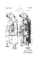
My invention is illustrated more or less diagrammatically in the accompanying drawings, wherein- Figure l is a plan View; Figure 2 is a plan view with parts omitted and parts broken away;
Figure 3 is a side elevation with parts in section and parts broken away;
Figure at is a section along the line 44 of Figure l;
Figure 5 is a section with parts omitted and parts broken away along the line 5-5 of Figure 2;
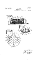
Figure 6 is a plan view of the headlight switch contact elements;
Figure 7 is a perspective View showing the headlight contact elements and control means.
Like parts are indicated by like characters throughout the specification and drawings.
A is the base or housing adapted to be held in place by bolts not shown, through the bolt holes A at any suitable point in the locomotive cab. It may be supported vertically or horizontally as the case may be. A is a conduit leading into the housing to contain conductor wires A A leading from the generator. .A is a conduit communicating with the housing to contain conductor wires A A leading to the headlight and to the cab lights. A is the resistance unit provided with legs A bolted to the housing A.
A is a cover for the housing held in place by the screws A.
Renewed August 28, 1931.
B is a boss in the cover A to provide a bearing for the switch pin B which pin has a switch fork B terminating in driving fingers B B inside the housing. The pin B projects outwardly beyond the boss B to engage the handle B being held against rotation thereon by means of the pin B which passes through the handle head and the pin and holds the pin and switch handle in position on the cover. B is a quadrant recessed on the face of the cover. A plurality of notches or pockets B B and B are formed in the cover A arranged in arcuate relation. Stops B are disposed at each end of the row of notches, serving as stops for the handle 13 as the same is swung to and fro as hereinafter described for establishing different circuit relations in the switch. A look plunger B is slidable in the hand piece B of the handle and is pressed outwardly against the quadrant by the spring B When the pin engages the pocket 13 as shown in Figure l, the headlight switch is in ofi position. When it has been swung to the left and engages the pocket B the headlight switch is in on position. When it is swung to the right engaging the pocket B the headlight switch is in the dim position.
C is an insulating block fastened in the housing by means of the screws 0 G is a conductor piece bolted to the block C. It has a binding post C at which terminates the cable A It also has an arm G extending to the center of the block C and carrying the pin 0 on which is rotatably mounted the switch member C". This switch member comprises two opposed plates disposed one on either side of a filler block 0 held yieldingly together by a spring 0 surrounding the pin C and held under tension by the cotter pin C These switch plates C have at opposed sides spaced spring fingers C C G C.
Mounted on the insulating block C is a dimmer contact D which, when the parts are in the position shown in dotted lines at the left hand side of Figure 2 is gripped between the members G C to close a circuit through the cable A binding post G pin C finger C C contact member D, conductor D binding post D conductor D to the resistance unit A Under these conditions a current leads from the other bolt through the resistance unit A conductor D, binding post D conductor D binding post D through the conductor A to the headlight, thus reducing the current and giving a dim light. When on the other hand the parts are in the position shown in full lines in Figure 2,.theblade C is in contactwith the terminal member D associated with the binding post D and in this case current leads from A through C C C the finger C, the member D direct to the conductor A and the full current pressure is supplied to the light thus short circuiting the resistance element. When the parts are in the position shown in Figure 6, however, both the terminalsD and D are idle and the light is turned completely off.
E is a driving plate concentric with the v plate-C spaced thereabove by means of holding pins E E This plate has a pair of diametrically opposed apertures E E adapted to engage the prongs or forks B B so that rotation of the hand switch causes rotation of'the switch members.
Referring now to the cab light switch, the conductor A comes into the housing to the binding post F. The conductor ATleads out through the housing from the binding post F F F are springs associated with said binding posts extendin inwardly toward each other. F 4 is a slida ly mounted contact block which, when pushed forward to the .35 dottedline position in Figure 2 engages both springs and when drawn to full line position, is out of contact with the spring F This block has a conducting surface F to engage these springfingers F while the body F thereof is of insulating material. This block slides on an insulating block F traveling between the guides F and has on its surface an upwardly bent lug stripF to enage theupwardly bent portion of a spring which sprin serves to hold the block either inlor out 0 contact with thespring F G is a switch handle slidable in a boss G in the housing having a pin Gr extending through the block F Springs G G are interposed between this rod-and this block so as to provide a flexible driving connection to insure that theoperator will not move the block too far in either direction if he hits the handle G too hard.
engaging the upper edge of the housin wall and contained between the outer rib 2 and the inner rib H on the cover A.
This application is a division of my copending application Ser. No. 128,112 August 9, 1926.
I claim:
1. A rotary switch for electric lights and the like, comprisingraninsnlatingblaak,in conductor pin. projecting wupwardly therefrom, a switch element rotatably mounted on and'in-electric connection therewith, a plurality of contact fingers on the block, pairs of opposed contact fingers on the switch element adapted. to grip the contact fingers on the block,the relative position of fingers onblock and switch element being suchthatin-Qne position they areall out of contact-with each other, and in other positions one pair only of the fingers on the switchv element are in con- 35 with bothfingers on the block.
2. A rotary switch for electric 1i hts and the like, comprising an inslllating lock,a conductor pin projecting upwardly therefrom, a switch element rotatably mounted on and in electric connection therewith, aphirality of contact fingers ontheblock, of opposed contact fingers on the switch element adapted to grip thecontact fingers on the block, the relative position of fingerson block and switch element being suchthat in one position they areall out ofcontact with each other, and in other positions one pair only of the fingers on the switch element are on in contact with a,finger.on the block, the parts being so arranged, however,that the switch element is never simultaneously in contact with both fingers on the blockyan'ins'ulating driving plate mountedupon the-switch element and insulated therefrom,-said drivi plate having apertures therein .anda-switc handle, a connector pin ,mounted ,to rotate with the handle and adapted to looselyengage an aperture in the driving-plate.
3. A rotary electric switch comprising .a central conducting pin, a switch element mounted for-rotation thereon, contact members in the path of the switch element, an apertured insulating driving plate mounted for rotation .on the pin and rotatably connected to the switch element, a fork loosely engaging the aperture and means to rotate the fork to operate the switch; a housing containing the switch, a removable cover therefor, the fork and the operating means bein mounted as a unit on the cover and adapted to operatively engage the driving member only when the cover is in place.
4. An electric switch comprising a. pair of conductor plates, havingeacha pairorfoon tact fingers proj ecting from its .periphery,:-su
perp osed in pairs and spaced apart, contact fingers fixed adjacent the peripheries of the plate and engageable by the spaced peripherial fin gers, an insulating plate parallel with the conductor plates and spaced above them, a driving connection between the insulating plate and the conductor plate, a terminal member, a pin projecting upwardly therethrough, a spring encircling such pin and holding the plates against the terminal member, means in cooperation with the insulating plate for limiting the angular movement of said plate, a handle above the plate having a driving pin adapted to engage apertures in the insulating plate whereby rotation of the handle will cause rotation of the conductor plate.
5. An electric switch comprising a pair of conductor plates having each a pair of contact fingers projecting from its periphery, superposed in pairs and spaced apart, contact fingers fixed adjacent the peripheries of the plates and engageable by the spaced peripherial fingers, an insulating plate parallel with the conductor plates and spaced above them, and a driving connection between the insulating plate and the conductor plate.
6. An electric switch comprising a pair of conductor plates, having each a pair of contact fingers projecting from its periphery, superposed in pairs and spaced apart, contact fingers fixed adjacent the peripheries of the plate, and engageable by the spaced peripherial fingers, an insulating plate parallel with the conductor plates and spaced above them, a driving connection between the insulating plate and the conductor plate, a terminal member, a pin projecting upwardly therethrough, a spring encircling such pin and holding the plates against the terminal member.
7. An electric switch comprising a pair of conductor plates, having each a pair of contact fingers projecting from its periphery, superposed in pairs and spaced apart, contact fingers fixed adjacent the peripheries of the plate, and engageable by the spaced peripherial fingers, an insulating plate parallel with the conductor plates and spaced above them, a driving connection between the insulating plate and the conductor plate, a terminal member, a pin projecting upwardly therethrough, a spring encircling such pin and holding the plates against the terminal member, means in cooperation with the insulat ing plate for limiting the angular movement of said plate.
Signed at Chicago, County of Cook, and State of Illinois, this 10th day of December,
JOHN A. AMOS.
Priority Applications (1)
| Application Number | Priority Date | Filing Date | Title |
|---|---|---|---|
| US155369A US1854919A (en) | 1926-08-09 | 1926-12-17 | Electric switch |
Applications Claiming Priority (2)
| Application Number | Priority Date | Filing Date | Title |
|---|---|---|---|
| US128112A US1820339A (en) | 1926-08-09 | 1926-08-09 | Electric switch |
| US155369A US1854919A (en) | 1926-08-09 | 1926-12-17 | Electric switch |
Publications (1)
| Publication Number | Publication Date |
|---|---|
| US1854919A true US1854919A (en) | 1932-04-19 |
Family
ID=26826275
Family Applications (1)
| Application Number | Title | Priority Date | Filing Date |
|---|---|---|---|
| US155369A Expired - Lifetime US1854919A (en) | 1926-08-09 | 1926-12-17 | Electric switch |
Country Status (1)
| Country | Link |
|---|---|
| US (1) | US1854919A (en) |
Cited By (1)
| Publication number | Priority date | Publication date | Assignee | Title |
|---|---|---|---|---|
| US2977430A (en) * | 1956-05-22 | 1961-03-28 | Chrysler Corp | Starter control device for automotive vehicles |
-
1926
- 1926-12-17 US US155369A patent/US1854919A/en not_active Expired - Lifetime
Cited By (1)
| Publication number | Priority date | Publication date | Assignee | Title |
|---|---|---|---|---|
| US2977430A (en) * | 1956-05-22 | 1961-03-28 | Chrysler Corp | Starter control device for automotive vehicles |
Similar Documents
| Publication | Publication Date | Title |
|---|---|---|
| US1854919A (en) | Electric switch | |
| US3944765A (en) | Combination turn-signal and hazard-warning switch means for an automobile | |
| US2306152A (en) | Reversing rheostat | |
| US1820339A (en) | Electric switch | |
| US1486744A (en) | Electric switch | |
| US1782916A (en) | Electric switch | |
| US1533188A (en) | Automatic switching device | |
| US1355701A (en) | Snap-switch for electrical heating apparatus | |
| US1447171A (en) | Switch | |
| US2209808A (en) | Lamp socket | |
| US1901653A (en) | Electric switch | |
| US1479520A (en) | Electric switch | |
| US756711A (en) | Electric controller for alternating currents. | |
| US2112510A (en) | Electrical socket | |
| US1517683A (en) | Pull-switch cluster | |
| US2427483A (en) | Multiple switch | |
| US3113258A (en) | Power control device | |
| US1539105A (en) | Signal lantern | |
| US1473838A (en) | Lever arm for switches, rheostats, and like electric devices | |
| US1519061A (en) | Electric switch | |
| US1592526A (en) | Electric switch | |
| US1399505A (en) | Lighting system and means for controlling the same | |
| US1661352A (en) | Electric switch | |
| US2619554A (en) | Switch unit | |
| US1304925A (en) | Homeb a |