US1854915A - Radio receiving system - Google Patents
Radio receiving system Download PDFInfo
- Publication number
- US1854915A US1854915A US248791A US24879128A US1854915A US 1854915 A US1854915 A US 1854915A US 248791 A US248791 A US 248791A US 24879128 A US24879128 A US 24879128A US 1854915 A US1854915 A US 1854915A
- Authority
- US
- United States
- Prior art keywords
- circuit
- coupling
- collector
- loop
- antenna
- Prior art date
- Legal status (The legal status is an assumption and is not a legal conclusion. Google has not performed a legal analysis and makes no representation as to the accuracy of the status listed.)
- Expired - Lifetime
Links
- 230000008878 coupling Effects 0.000 description 26
- 238000010168 coupling process Methods 0.000 description 26
- 238000005859 coupling reaction Methods 0.000 description 26
- 230000000694 effects Effects 0.000 description 5
- 230000004075 alteration Effects 0.000 description 2
- 235000014443 Pyrus communis Nutrition 0.000 description 1
- 238000010586 diagram Methods 0.000 description 1
- 230000001939 inductive effect Effects 0.000 description 1
- 230000011664 signaling Effects 0.000 description 1
Images
Classifications
-
- H—ELECTRICITY
- H03—ELECTRONIC CIRCUITRY
- H03H—IMPEDANCE NETWORKS, e.g. RESONANT CIRCUITS; RESONATORS
- H03H2/00—Networks using elements or techniques not provided for in groups H03H3/00 - H03H21/00
- H03H2/005—Coupling circuits between transmission lines or antennas and transmitters, receivers or amplifiers
- H03H2/008—Receiver or amplifier input circuits
Definitions
- This-invention relates to radio receiving systemsand sets. in, which the circuits used are adapted l to. be interchangeably connected withany. type of antenna, including the high- 5; lycapacitive elevated collector and the highly inductive loop. or directional collector. type.
- Heretoforercircuits have notbeen arranged insuch' a Way,that:either typeof an-tenna may be connected. without. making; some changes in theconstantsof the circuitsin keeping with the more or less opposed electrical .characteristics of the two types :ofcollectors.
- the arrangement also adapts, itself to they use -of antennaer having different electrostatic; and
- This also causes any antenna circuit. connects edito .the input circuit 12 to be substantially detunedfrom the frequency band. in which operating. This adjustment avoidsethe production of. a resonant peakwithin the range offfrequencies usedwhich ifhad, would tend to make securing a substantially constant energy input practically impossible.
- the combined coupling is composed .offthe electromagnetic coupling between coil 16, connected in series withthe, adjustablecapacity 17 a and the fixed .capacity 18, and coil 21, and the electrostatic couplingacross cons, denser18.
- the combined coupling can bemade to transfer energy in any desired way with frequency, .such as keeping constant, and may be madeastight as desired and maintained so with" frequency features more fully described in mycopending application Serial Number 48936, filed August 8, 1925.
- This arrangement permits having two terminals 2 and 3 on a radio cabinet 1, to which either the loop antenna 7 or the elevated electrostatic antenna 5 may be connected without making any alterations or change of adjustment in the receiver, and does not require any variable or other tuning element in the loop to obtain efficient results, as is the case with previously known loop arrangements.
- the terminals 2 and 3 being connected to a tunable circuit 16, 17 and 18 through the high impedance 14 and the combined coupling have been found suitable connections for any type of antenna.
- the en ergy is resonantly abstracted from either the elevated antenna or loop antenna by the selective circuit 16, 17 18, which has an ef fect equivalent to tuning the antenna circuit, thus making special tuning for these circuits unnecessary.
- the translating device 13 may be in the form of a vacuum tube or any other energy transfer arrangement.
- a source of high potential may be applied to the terminals 23 and the output of the device taken off at 24 in any desired way.
- a radio receiver input system including a loop collector, a translating system, a circuit tunable. through a Wide range of frequencies connected across said translating system, a combined electrostatic and .electromagnetic input coupling poled to transfer energy in phase to said circuit, said electromagnetic coupling being less than 100 per cent, and a high impedance capacity connection between the terminals of said collector and the terminals of said coupling.
- a radio receiver input system including a loop collector, a translating system, a circuit tunable through a wide range of frequencies connected across said translating system, a combined electrostatic and electromagnetic input coupling poled to transfer energy in phase to said circuit, the circuit of said loop collector being completed through said coupling, and impedance means in said completed loop circuit so chosen as to prevent said loop circuit from becoming resonant at any frequency within the operating range of frequencies of said tunable circuit.
- a radio receiving system the combination of a loop collector, a translating device having a resonant input circuit, a combined electrostatic and electro-magnetic coupling between said loop and said resonant circuit so poled as to transfer energy electrostatically and electromagnetically in phase from said loop to said resonant circuit, said electrostatic coupling forming a portion of said resonant circuit and means for isolating the tuning effects in said resonant circuit from said loop collector.
- a radio receiving system the combination of a collector, a translating device having a resonant input circuit tunable to incoming signal frequencies, a combined electrostatic and electromagnetic coupling between said collector and said resonant circuit so poled as to transfer energy electrostatically and electromagnetically in phase from said collector to said resonant circuit,
- a radio receiver input system the combination of an untuned loop collector, a translating system, a circuit tunable through a wide range of frequencies connected across said translating system, an input coupling to said circuit including means for transferring energy increasingly with decrease of current frequency and means for transfering energy in phase with said first transfer means decreasingly with decrease of cur rent frequency, and high impedance capacity means completing the circuit of said loop collector through said coupling means.
- a radio receiver input system the combination of a collector, a translating system, a circuit tunable through a wide range of incoming signal frequencies connected across said translating system, means for transferring energy from said collector to saidcircuitincreasinglywithincrease of current frequency, means for transferring energy from said collector to said circuit decreasingly with increase of current frequency, said transfer means being poled to transfer energy in phase accord and adjusted to transfer energy at substantially the same rates throughout their reversed energy transfer-frequency characteristics, and means materially isolating the tuning effects in said circuit from said collector.
- an antenna system having two terminals, a translating device, a circuit tunable through a range of incoming signal frequencies coupled to said translating device, a combined electrostatic and electromagnetic coupling poled to transfer energy in aiding phase to said tunable circuit, said electrostatic coupling forming a portion of the tuning means of said tunable circuit and also a path for current flowing between said terminals and a connection between said antenna terminals and said coupling whereby ener is transferred at substantially uniform e ciency through said coupling at the several frequencies over which said first named circuit is tunable.
Landscapes
- Input Circuits Of Receivers And Coupling Of Receivers And Audio Equipment (AREA)
Description
April 1932- 5. Y. WHITE RADIO RECEIVING SYSTEM Filed Jan. 25, 1928 v INVENTOR 5/0/VEY X WM TE ATTORNEY Patented Apr. 19, 1932 UNITED STATES,
Parent osFelciei SIDNEY Y..WHITE, OF .NEW YORK, N. Y ASSIGNOR, BYMESNE ASSIGNMENTS,- TO RADIO CORPORATION" OF AMERICA, OENEW1YORK; N. Y., A CORPORATION OF DELAWARE RADIO 'n'ncnrvnve SYSTEM?- Applicatibn filed January 23, 1928. Seria1 No. 248,791.
This-invention relates to radio receiving systemsand sets. in, which the circuits used are adapted l to. be interchangeably connected withany. type of antenna, including the high- 5; lycapacitive elevated collector and the highly inductive loop. or directional collector. type. Heretoforercircuits have notbeen arranged insuch' a Way,that:either typeof an-tenna may be connected. without. making; some changes in theconstantsof the circuitsin keeping with the more or less opposed electrical .characteristics of the two types :ofcollectors. The arrangement also adapts, itself to they use -of antennaer having different electrostatic; and
Y electromagnetic characteristics.
Iteis: anlobject ofthisinvention to pro? vide a radio receiving. system which may be interchangeably connected to. anyofthe types:
of. antennae now. common. and Well known without. requiring. alterations. confusing to the unskilled operator.
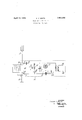
Further and more definite objects wil1.ap= pear from .therfollowingspecification, claims and drawing,in which the single figure represents a. schematic; diagram of my arrangement.
This drawingshows a circuit enclosed with inthe confines of acabinetor other container indicated bythe dotted linel. Binding posts ao ortother connections 2and3dnay=be located upon the: cabinet 1 and interchangeably associated-withtheelevated antenna .5 and ground arrangementfi'uor the lo0p,or directional antenna 7 This interchangeability isindicated by,simu ltaneously operable. switchesS and 9 connected 'byasuitable insulating linkage or other, arrangement ,10, indicated by the brokenlineginsuch a lway thatin one position these switcheswillconnect a loop 7 and in the other position the elevated antenna 5. and
groundVG-L. Ofcoursethe switches may be dispensed with and connections made directly torthebindingposts 2: and'3.
In order to' permit this-interchange ability the-reflectsOfthe-idiiferent .typesof antennae upon a circuitlQ, as inputtothe translating. device-13', in so far. as the effects vary the selectivity or tuning of this circuit, mustbe. kept low and uniform with frequency. This result, it has been found, can be obtained by utilizing what. is commonly known. as. a. combined electrostatic. and electromagnetic coupling arrangement whereindiiferent frequencies throughout a range of frequencies:
received are. transmit-ted through this: coupling with substantially uniform efficiencies. The coupling may beniade more or=less.inde.- pendentto suit the desired needsby connectingin the circuitthe proper impedance 14:. which has been found to act. outsatisfactorily when in-the form of .a-small capacity. This also causes any antenna circuit. connects edito .the input circuit 12 to be substantially detunedfrom the frequency band. in which operating. This adjustment avoidsethe production of. a resonant peakwithin the range offfrequencies usedwhich ifhad, would tend to make securing a substantially constant energy input practically impossible.
The combined coupling is composed .offthe electromagnetic coupling between coil 16, connected in series withthe, adjustablecapacity 17 a and the fixed .capacity 18, and coil 21, and the electrostatic couplingacross cons, denser18. By selectingthe polarity oftlie electromagnetic couplingto aid the electrostatic coupling, and selecting proper values of each kind of coupling, the combined coupling can bemade to transfer energy in any desired way with frequency, .such as keeping constant, and may be madeastight as desired and maintained so with" frequency features more fully described in mycopending application Serial Number 48936, filed August 8, 1925. Thetighter this'coupling the better will be the transmissiorrxof the effect of tunin'gqtheadjustable condenser"17 back onto the antenna circuit, and thusby utilizing: :a combined a coupling as indicated a tight couplingcan bemaintai-ned uniformly effective for this purpose throughout a wide range of frequencies, as for instance, the broadcast range.
This arrangement permits having two terminals 2 and 3 on a radio cabinet 1, to which either the loop antenna 7 or the elevated electrostatic antenna 5 may be connected without making any alterations or change of adjustment in the receiver, and does not require any variable or other tuning element in the loop to obtain efficient results, as is the case with previously known loop arrangements. The terminals 2 and 3 being connected to a tunable circuit 16, 17 and 18 through the high impedance 14 and the combined coupling have been found suitable connections for any type of antenna. The en ergy is resonantly abstracted from either the elevated antenna or loop antenna by the selective circuit 16, 17 18, which has an ef fect equivalent to tuning the antenna circuit, thus making special tuning for these circuits unnecessary.
The translating device 13 may be in the form of a vacuum tube or any other energy transfer arrangement. A source of high potential may be applied to the terminals 23 and the output of the device taken off at 24 in any desired way.
It is not intended to be limited to the eX- act arrangements shown for considerable departure therefrom is possible without departing from the spirit and scope of the in vention. The various elements of the circuit may be made adjustable both as to coupling or electrical values. Equivalent eleinents may be substituted for those shown.
It is intended to be limited only to the extent indicated in the following claims.
I claim:
1. A radio receiver input system including a loop collector, a translating system, a circuit tunable. through a Wide range of frequencies connected across said translating system, a combined electrostatic and .electromagnetic input coupling poled to transfer energy in phase to said circuit, said electromagnetic coupling being less than 100 per cent, and a high impedance capacity connection between the terminals of said collector and the terminals of said coupling.
2. A radio receiver input system including a loop collector, a translating system, a circuit tunable through a wide range of frequencies connected across said translating system, a combined electrostatic and electromagnetic input coupling poled to transfer energy in phase to said circuit, the circuit of said loop collector being completed through said coupling, and impedance means in said completed loop circuit so chosen as to prevent said loop circuit from becoming resonant at any frequency within the operating range of frequencies of said tunable circuit.
3. In a radio receiving system, the combination of a loop collector, a translating device having a resonant input circuit, a combined electrostatic and electro-magnetic coupling between said loop and said resonant circuit so poled as to transfer energy electrostatically and electromagnetically in phase from said loop to said resonant circuit, said electrostatic coupling forming a portion of said resonant circuit and means for isolating the tuning effects in said resonant circuit from said loop collector.
4. In a radio receiving system, the combination of a collector, a translating device having a resonant input circuit tunable to incoming signal frequencies, a combined electrostatic and electromagnetic coupling between said collector and said resonant circuit so poled as to transfer energy electrostatically and electromagnetically in phase from said collector to said resonant circuit,
and so related that the combined electromagnetic and electrostatic transfer of energy is substantially constant throughout the frequency range of said resonant circuit, and means for isolating the tuning effects in said resonant circuit from said collector, whereby said collector is rendered substantially aperiodic throughout the frequency range of said resonant circuit.
5. In a radio receiver input system, the combination of an untuned loop collector, a translating system, a circuit tunable through a wide range of frequencies connected across said translating system, an input coupling to said circuit including means for transferring energy increasingly with decrease of current frequency and means for transfering energy in phase with said first transfer means decreasingly with decrease of cur rent frequency, and high impedance capacity means completing the circuit of said loop collector through said coupling means.
6. In a radio receiver input system, the combination of a collector, a translating system, a circuit tunable through a wide range of incoming signal frequencies connected across said translating system, means for transferring energy from said collector to saidcircuitincreasinglywithincrease of current frequency, means for transferring energy from said collector to said circuit decreasingly with increase of current frequency, said transfer means being poled to transfer energy in phase accord and adjusted to transfer energy at substantially the same rates throughout their reversed energy transfer-frequency characteristics, and means materially isolating the tuning effects in said circuit from said collector.
7. In a radio signalling system, an antenna system having two terminals, a translating device, a circuit tunable through a range of incoming signal frequencies coupled to said translating device, a combined electrostatic and electromagnetic coupling poled to transfer energy in aiding phase to said tunable circuit, said electrostatic coupling forming a portion of the tuning means of said tunable circuit and also a path for current flowing between said terminals and a connection between said antenna terminals and said coupling whereby ener is transferred at substantially uniform e ciency through said coupling at the several frequencies over which said first named circuit is tunable.
In testimony whereof I afiix my si nature.
SIDNEY Y. W ITE.
Priority Applications (1)
| Application Number | Priority Date | Filing Date | Title |
|---|---|---|---|
| US248791A US1854915A (en) | 1928-01-23 | 1928-01-23 | Radio receiving system |
Applications Claiming Priority (1)
| Application Number | Priority Date | Filing Date | Title |
|---|---|---|---|
| US248791A US1854915A (en) | 1928-01-23 | 1928-01-23 | Radio receiving system |
Publications (1)
| Publication Number | Publication Date |
|---|---|
| US1854915A true US1854915A (en) | 1932-04-19 |
Family
ID=22940693
Family Applications (1)
| Application Number | Title | Priority Date | Filing Date |
|---|---|---|---|
| US248791A Expired - Lifetime US1854915A (en) | 1928-01-23 | 1928-01-23 | Radio receiving system |
Country Status (1)
| Country | Link |
|---|---|
| US (1) | US1854915A (en) |
Cited By (2)
| Publication number | Priority date | Publication date | Assignee | Title |
|---|---|---|---|---|
| US2511662A (en) * | 1945-01-19 | 1950-06-13 | Gen Electric | Permeability tuned loop antenna circuit |
| US2538497A (en) * | 1947-11-12 | 1951-01-16 | Avco Mfg Corp | Antenna connector system |
-
1928
- 1928-01-23 US US248791A patent/US1854915A/en not_active Expired - Lifetime
Cited By (2)
| Publication number | Priority date | Publication date | Assignee | Title |
|---|---|---|---|---|
| US2511662A (en) * | 1945-01-19 | 1950-06-13 | Gen Electric | Permeability tuned loop antenna circuit |
| US2538497A (en) * | 1947-11-12 | 1951-01-16 | Avco Mfg Corp | Antenna connector system |
Similar Documents
| Publication | Publication Date | Title |
|---|---|---|
| US2211750A (en) | Wireless telegraph system | |
| GB2071920A (en) | Aerial circuit | |
| US1854915A (en) | Radio receiving system | |
| US2511574A (en) | Antenna circuit | |
| US1719484A (en) | Carrier transmission system | |
| US2205365A (en) | Radio receiver | |
| US2226836A (en) | Interference-reducing system | |
| US1476691A (en) | Electrical signaling | |
| US1917291A (en) | Method and means for eliminating fading | |
| US1982771A (en) | High frequency wave modulation | |
| US1715701A (en) | Inghottse electric | |
| US2971161A (en) | I.f amplifier with electronically controllable band-pass | |
| US1795689A (en) | Antenna | |
| US2195301A (en) | Radio receiver | |
| US1725721A (en) | Method and means for combining frequencies | |
| US2215774A (en) | Combined wired radio and space radio receiving system | |
| US1609805A (en) | Radio receiving system | |
| US956165A (en) | Electrical space communication. | |
| US1740969A (en) | Duplex transmission system | |
| US1821650A (en) | Radio system | |
| US786132A (en) | Wireless telegraphy. | |
| US2097880A (en) | Radio receiving system | |
| US1838855A (en) | Circuit arrangement for multiple-unit tubes | |
| US1964570A (en) | Directional antenna arrangement | |
| US1375992A (en) | Radio-receiving system |