US1854891A - Vise - Google Patents
Vise Download PDFInfo
- Publication number
- US1854891A US1854891A US538496A US53849831A US1854891A US 1854891 A US1854891 A US 1854891A US 538496 A US538496 A US 538496A US 53849831 A US53849831 A US 53849831A US 1854891 A US1854891 A US 1854891A
- Authority
- US
- United States
- Prior art keywords
- bar
- jaw
- shaft
- vise
- eccentric
- Prior art date
- Legal status (The legal status is an assumption and is not a legal conclusion. Google has not performed a legal analysis and makes no representation as to the accuracy of the status listed.)
- Expired - Lifetime
Links
- 239000011435 rock Substances 0.000 description 5
- 230000000284 resting effect Effects 0.000 description 4
- 230000000694 effects Effects 0.000 description 3
- 230000000295 complement effect Effects 0.000 description 2
- KHOITXIGCFIULA-UHFFFAOYSA-N Alophen Chemical compound C1=CC(OC(=O)C)=CC=C1C(C=1N=CC=CC=1)C1=CC=C(OC(C)=O)C=C1 KHOITXIGCFIULA-UHFFFAOYSA-N 0.000 description 1
- 229910000831 Steel Inorganic materials 0.000 description 1
- 239000008186 active pharmaceutical agent Substances 0.000 description 1
- 230000005484 gravity Effects 0.000 description 1
- 238000009877 rendering Methods 0.000 description 1
- 239000010959 steel Substances 0.000 description 1
Images
Classifications
-
- B—PERFORMING OPERATIONS; TRANSPORTING
- B25—HAND TOOLS; PORTABLE POWER-DRIVEN TOOLS; MANIPULATORS
- B25B—TOOLS OR BENCH DEVICES NOT OTHERWISE PROVIDED FOR, FOR FASTENING, CONNECTING, DISENGAGING OR HOLDING
- B25B1/00—Vices
- B25B1/06—Arrangements for positively actuating jaws
- B25B1/08—Arrangements for positively actuating jaws using cams
-
- B—PERFORMING OPERATIONS; TRANSPORTING
- B25—HAND TOOLS; PORTABLE POWER-DRIVEN TOOLS; MANIPULATORS
- B25B—TOOLS OR BENCH DEVICES NOT OTHERWISE PROVIDED FOR, FOR FASTENING, CONNECTING, DISENGAGING OR HOLDING
- B25B1/00—Vices
- B25B1/06—Arrangements for positively actuating jaws
- B25B1/10—Arrangements for positively actuating jaws using screws
- B25B1/12—Arrangements for positively actuating jaws using screws with provision for disengagement
Definitions
- This invention relates to improvements in bench and other Vises, and has for its object to provide novel, powerful and quick-acting means for locking the complementary parts of the vise.
- a further object is to provide a vise having the customary stationary and gripping jaws, the latter being movable relatively to the fixed jaw, with which it connects by a guidebar which plays reciprocally in a slotted opening that extends through the fixed body below the plane of the jaws proper;
- the body of the fixed jaw is bored at right angles to the guide-bar opening to receive and afford a bearing for an operating shaft, the said shaft'being formed with an eccentric portion which is positioned directly over said bar and controls the locking and releasing of the movable jaw.
- a further object is to provide a novel and simple locking member which is normally loosely disposed within a cavity that communicates with said opening, the said member resting upon the top face of said bar, and registering with the eccentric portion of the shaft which holds said member in place, and said member being movable towards the locking position by simply rocking the shaft in. either direction.
- a further object is to provide a vise whose jaws may be readily and quickly adjusted and locked without depending upon screws or other threaded means, and without changing the angles of the complementary gripping surfaces of the jaws.
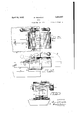
- Figure 1 is a top plan view of the vise when closed.
- Fig; 2 is an end elevation of the same.
- Fig. 3 is a front side elevation, taken in the direction of the arrow in Fig. I. 4 is a partial end elevation and central vertical sec-'- tion, the latter being taken on line 44; of Fig. 1, showing the jaws gripping a piece of work; also showing the locking member held in the locking position by the eccentric.
- Fig. 5 is a horizontal section. taken on line 55 of Fig. 4.
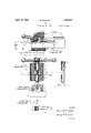
- Fig. 6 is a. fragmentary section, showing the locking member released.
- Fig. 7 is an end View of the locking member.
- Fig. 1 is a top plan view of the vise when closed.
- Fig. 2 is an end elevation of the same.
- Fig. 8 is a top plan view of the same.
- Fig. 9 is a side elevation of the operating shaft.
- the present vise comprises two jaws, as 2 and 3.
- the jaw 2' is preferably stationary or fixed, and may be rigidly mounted upon a bench or table, as hand for this purpose
- the body 2 is formed with a flange base 2.
- the body 2 is formed with an angular horizontal opening, as 2a, and also with a cavity or chamber 20 that communicates with said opening.
- the body2 is bored, as at 26, to intersect said cavity at right angles to the ing 2a, toreceive and provide bearings for a shaft 5, the latter having a medial eccentric portion 5 that is disposed in the cavity 20.
- One end of the shaft may be formed with a head, as 5a,which bears against the adjacent end of body 2, while its opposite end projects slightly beyond the corresponding end of the body and is perforated to receive a cotter-pin5c,bywhichthe shaft is removably held in place, as shown inFigs. 1 to 6 inclusive.
- the shaft" 5 may be rotated by any suitable handle, that may comprise a cylindrical body 6, which is formed with an axial socketto receive the head 5a, and said body is also perforated diametrically, as at 60, to slidably receive an operating rod 60, by which the shaft 5' may be rocked. to effect the looking, as well as to. facilitate variousadjnstmentsof the movable jaw 3.
- the jaw 3 has a gripping surface 3 that registers'with the corresponding surface 250 of body 2.
- body 3 is fitted with a relatively long horizontal bar or guide guide, as 3a, one end of which is preferably cast in the lower portion of said body, the said bar preferably being made of steel and having the same angularityin cross-section as the opening 20, which said bar is adapted to slide when the body 3 is moved towards or from the body 2, as may be understood by comparing Fig. I with Figs. 2 and 4.
- the bar 3a is the only means to connect the bodies 2 and 3 and said bar may be provided with a stop, as 30, to prevent the complete detachment of the parts.
- the bar 3a substantially closes the lower side of the cavity- 20, as shown in Figs. 1 and 6.
- the locking of the movable or gripping jaw 3 in different positions relatively to the body 2 is preferably effected by a peculiarly shaped member or dog 7, which is loosely and rockably disposed in the cavity 20, and rests by gravity upon the top face of the bar 3a, as best seen in Figs. 4 and 6.
- the member 7 is formed at one end with a wedge-shaped portion 7, which is normally disposed in a similarly shaped recess or crotch 261, that is defined by an inclined surface or wall 26 of the cavity 20 and the top face of the bar 3a (see Figs. 4 and 6).
- the body of dog 7 curves upwardly rocker-like from the bar 3a and its opposite end is formed with a concave socket 7a, which is concentric to and normally loosely engages the eccentric as when the parts are in the unlocked position, shown in Fig. 6.
- the movements of the locking member 7 in the cavity are therefore limited to the extremely short throw of the crank 5' and the slight looseness of the wedge 7 so that said member is not liable to accidentally escape from either the crotch 2d or the eccentric 5'.
- the jaw 3 may be freely moved towards or away from body 2, without disturbing the dog 7, and when the said jaw is suitably adjusted for clamping a piece of work, as A, shown in Fig.
- the jaw 3 may be instantly and securely locked in the clamping position, as by the swinging of the handle 60 from the full-line position of Fig. 2 to the full-line position of Fig. 4.
- This relatively slight movement of the hand rod 60 causes the eccentric or crank to swing downwardly and laterally and force the wedge 7 into crotch 2d for making the guide bar 3a rigid to body 2, as shown in Fig. 4, and whatever the direction of motion of the member 7 during the locking operations may be, the said member being in constant frictional engagement with the bar 3a, tends always to draw said bar towards the body 2 to tighten the grip upon the work.
- the locking of the guide 3a may be effected equally well by rocking the rod in either clockwise or reverseclockwise directions.
- the constant nesting of the eccentric 5' in the concentric socket 7 a not only renders failure of the locking action impossible, but enables the shaft 5 to effect the quick and powerful locking of the guide 3a to the body 2, whether or not the vise is disposed as shown in the drawings, or tilted or disposed in any other position.
- the slight looseness of member 7, as shown by comparison of Figs. 4 and 6 renders the looking means so sensitive that it only requires a very slight rocking of the handle 60 to perform the locking work.
- a vise comprising a fixed and a movable jaw, the fixed jaw having a transverse opening, the movable jaw having a guide-bar slidable in said opening, whereby the latter jaw may be moved relatively to the fixed jaw, said fixed jaw being bored at right angles to said bar to receive a rock shaft, said shaft being formed with an eccentric portion that registers with said bar, a lock- 5 ing member-resting upon said bar and having a socket in which said eccentric nests, and means to rock said shaft.
- a vise including a stationary and a movable jaw, said movable jaw having ar guide-arm that passes loosely through the stationary jaw, a shaft journaled in the stationary jaw at right angles to said arm, having an eccentric portion that registers with the arm, and a locking member resting upon said arm and loosely engaging said eccentric, adapted to lock said arm rigidly to the stationary jaw by the rocking of said shaft in opposite directions.
- a vise including a fixed jaw and a gripping jaw, said gripping jaw having a guide-arm that operatively passes through the body of the fixed jaw, a shaft journaled in the fixed aw at right angles to said arm, having an eccentric portion that conincides with the top face of the arm, and a locking member resting upon said arm adapted to be engaged with said eccentric portion to lock said arm to the fixed jaw by the manual rocking of said shaft.
- A. vise including a fixed jaw having an opening therethrough and a gripping jaw, the latter jaw having a guide-bar loosely disposed in said opening to enable the said jaw to be moved relatively to the fixed jaw,
- a shaft disposed in the body of the fixed aw at right angles to said guide bar, having an eccentric portion above and spaced from the top face of said bar, and a floatable locking member riding upon said bar and loosely en- L gaging said eccentric portion adapted to lock said bar to the fixed jaw by the rocking of said shaft.
- a vise including a fixed and a movable jaw, said fixed jaw being formed with a transverse opening, said movable jaw being formed with a guide-bar adapted to slide in said opening to enable the movable jaw to be adjusted relatively to the fixed jaw, a shaft journaled in the fixed jaw above and at an angle to the guide-bar, said shaft being formed with a crank portion, and a floatable locking member mounted upon the top face of said bar adapted to be moved longitudinally on said bar by the rocking of said shaft to lock said jaws in different positions relatively to each other.
- a vise including a fixed jaw having a transverse opening, and a movable jaw having a guide-bar slidable in said opening, said opening having a Wall that inclines upwardly from said bar to provide a crotch, a shaft journaled in said fixed jaw above and at right angles to said bar, said shaft having an eccentric portion that registers with said bar and said crotch, a locking member resting frictionally upon said bar having a socket loosely engaged by said eccentric and having a wedge-shaped portion loosely disposed in said crotch, and means to rock said shaft for forcing said wedge-shaped portion tightly into said crotch to effectually lock said jaws in work-gripping positions.
- a vise comprising a fixed and a movable jaw, the fixed jaw having a transverse opening, a portion of said opening being defined by an inclined surface, the movable jaw having a guide-bar slidable in said opening whereby the latter jaw may be moved relatively to the fixed jaw, the top face of said guide-bar and said inclined surface forming a crotch, said fixed aw being bored at right angles to said bar to receive a rock shaft, said shaft being formed with an eccentric portion that registers with said bar and said crotch, a locking member mounted upon said bar and having a socket at one end in which said eccentric nests, and means to rock said shaft to enable said eccentric portion to move the opposite end of said member into said crotch to effect the locking of said jaws.
Landscapes
- Engineering & Computer Science (AREA)
- Mechanical Engineering (AREA)
- Gripping Jigs, Holding Jigs, And Positioning Jigs (AREA)
Description
B. DWOFSKY April 19, 1932.
VISE
Filed May 19, 1931 2 Sh'eetsSheet F Frcl A TTORNEY."
B. DWOFSKY April 19, 1932.
vIsE
Filed May 19, 1931 2 Sheets-Sheet 2- INVENTOR ATTO RN EY,
Patented Apr. 19, 1932 UNITED STATES PATENT OFFICE BERNARD DWOFSKY, OI SYRACUSEL'NEW YORK, ASSIGNOR OF TWO-THIB-DS TO BENJA- MIN E. HOB-TON AND DONOVAN "W. HORTON, BOTH OF SYRACUSE, NEW YORK vIsE Application filed as] 19, 1931'. serial 33,498.
This invention relates to improvements in bench and other Vises, and has for its object to provide novel, powerful and quick-acting means for locking the complementary parts of the vise. A further object is to provide a vise having the customary stationary and gripping jaws, the latter being movable relatively to the fixed jaw, with which it connects by a guidebar which plays reciprocally in a slotted opening that extends through the fixed body below the plane of the jaws proper; The body of the fixed jaw is bored at right angles to the guide-bar opening to receive and afford a bearing for an operating shaft, the said shaft'being formed with an eccentric portion which is positioned directly over said bar and controls the locking and releasing of the movable jaw. A further object is to provide a novel and simple locking member which is normally loosely disposed within a cavity that communicates with said opening, the said member resting upon the top face of said bar, and registering with the eccentric portion of the shaft which holds said member in place, and said member being movable towards the locking position by simply rocking the shaft in. either direction. And a further object is to provide a vise whose jaws may be readily and quickly adjusted and locked without depending upon screws or other threaded means, and without changing the angles of the complementary gripping surfaces of the jaws.
I attain these objects by the means set forth in the detailed description which follows,
and as illustrated by the accompanying drawings, in which Figure 1 is a top plan view of the vise when closed. Fig; 2 is an end elevation of the same. Fig. 3 is a front side elevation, taken in the direction of the arrow in Fig. I. 4 is a partial end elevation and central vertical sec-'- tion, the latter being taken on line 44; of Fig. 1, showing the jaws gripping a piece of work; also showing the locking member held in the locking position by the eccentric. Fig. 5 is a horizontal section. taken on line 55 of Fig. 4. Fig. 6 is a. fragmentary section, showing the locking member released. Fig. 7 is an end View of the locking member. Fig.
8 is a top plan view of the same. And Fig. 9 is a side elevation of the operating shaft.
I 4 According to the drawings, the present vise comprises two jaws, as 2 and 3. The jaw 2'is preferably stationary or fixed, and may be rigidly mounted upon a bench or table, as hand for this purpose the body 2 is formed with a flange base 2. Above this base, the body 2 is formed with an angular horizontal opening, as 2a, and also with a cavity or chamber 20 that communicates with said opening. The body2 is bored, as at 26, to intersect said cavity at right angles to the ing 2a, toreceive and provide bearings for a shaft 5, the latter having a medial eccentric portion 5 that is disposed in the cavity 20. One end of the shaft may be formed with a head, as 5a,which bears against the adjacent end of body 2, while its opposite end projects slightly beyond the corresponding end of the body and is perforated to receive a cotter-pin5c,bywhichthe shaft is removably held in place, as shown inFigs. 1 to 6 inclusive. The shaft" 5 may be rotated by any suitable handle, that may comprise a cylindrical body 6, which is formed with an axial socketto receive the head 5a, and said body is also perforated diametrically, as at 60, to slidably receive an operating rod 60, by which the shaft 5' may be rocked. to effect the looking, as well as to. facilitate variousadjnstmentsof the movable jaw 3. The jaw 3 has a gripping surface 3 that registers'with the corresponding surface 250 of body 2. Below the gripping face 3, body 3 is fitted with a relatively long horizontal bar or guide guide, as 3a, one end of which is preferably cast in the lower portion of said body, the said bar preferably being made of steel and having the same angularityin cross-section as the opening 20, which said bar is adapted to slide when the body 3 is moved towards or from the body 2, as may be understood by comparing Fig. I with Figs. 2 and 4. The bar 3a is the only means to connect the bodies 2 and 3 and said bar may be provided with a stop, as 30, to prevent the complete detachment of the parts. The bar 3a substantially closes the lower side of the cavity- 20, as shown in Figs. 1 and 6.
The locking of the movable or gripping jaw 3 in different positions relatively to the body 2 is preferably effected by a peculiarly shaped member or dog 7, which is loosely and rockably disposed in the cavity 20, and rests by gravity upon the top face of the bar 3a, as best seen in Figs. 4 and 6. The member 7 is formed at one end with a wedge-shaped portion 7, which is normally disposed in a similarly shaped recess or crotch 261, that is defined by an inclined surface or wall 26 of the cavity 20 and the top face of the bar 3a (see Figs. 4 and 6). The body of dog 7 curves upwardly rocker-like from the bar 3a and its opposite end is formed with a concave socket 7a, which is concentric to and normally loosely engages the eccentric as when the parts are in the unlocked position, shown in Fig. 6. The movements of the locking member 7 in the cavity are therefore limited to the extremely short throw of the crank 5' and the slight looseness of the wedge 7 so that said member is not liable to accidentally escape from either the crotch 2d or the eccentric 5'. When the eccentric 5 and the dog 7 are in the inoperative positions of Fig. 6, the jaw 3 may be freely moved towards or away from body 2, without disturbing the dog 7, and when the said jaw is suitably adjusted for clamping a piece of work, as A, shown in Fig. 4, the jaw 3 may be instantly and securely locked in the clamping position, as by the swinging of the handle 60 from the full-line position of Fig. 2 to the full-line position of Fig. 4. This relatively slight movement of the hand rod 60 causes the eccentric or crank to swing downwardly and laterally and force the wedge 7 into crotch 2d for making the guide bar 3a rigid to body 2, as shown in Fig. 4, and whatever the direction of motion of the member 7 during the locking operations may be, the said member being in constant frictional engagement with the bar 3a, tends always to draw said bar towards the body 2 to tighten the grip upon the work.
In practice, owing to the peculiar shape of the locking member 7 the arrangement of the crotch 2d. and the relation of the eccentric 5 to said member, the locking of the guide 3a may be effected equally well by rocking the rod in either clockwise or reverseclockwise directions. The constant nesting of the eccentric 5' in the concentric socket 7 a, not only renders failure of the locking action impossible, but enables the shaft 5 to effect the quick and powerful locking of the guide 3a to the body 2, whether or not the vise is disposed as shown in the drawings, or tilted or disposed in any other position. The slight looseness of member 7, as shown by comparison of Figs. 4 and 6 renders the looking means so sensitive that it only requires a very slight rocking of the handle 60 to perform the locking work. The complete detachment of the member 7 from either the body 2 or shaft 5 obviates all danger of said member becoming cramped or dislocated and thereby rendering it inoperable. When the parts 2 and 3 are locked, as shown in Fig. 4, the vise will withstand extremely rough usage, such as heavy blows, prying or wrenching of the work A, without danger of. loosening the member 7.
Having thus described my invention, what I claim, is-
1. A vise, comprising a fixed and a movable jaw, the fixed jaw having a transverse opening, the movable jaw having a guide-bar slidable in said opening, whereby the latter jaw may be moved relatively to the fixed jaw, said fixed jaw being bored at right angles to said bar to receive a rock shaft, said shaft being formed with an eccentric portion that registers with said bar, a lock- 5 ing member-resting upon said bar and having a socket in which said eccentric nests, and means to rock said shaft.
2. A vise, including a stationary and a movable jaw, said movable jaw having ar guide-arm that passes loosely through the stationary jaw, a shaft journaled in the stationary jaw at right angles to said arm, having an eccentric portion that registers with the arm, and a locking member resting upon said arm and loosely engaging said eccentric, adapted to lock said arm rigidly to the stationary jaw by the rocking of said shaft in opposite directions.
3. A vise, including a fixed jaw and a gripping jaw, said gripping jaw having a guide-arm that operatively passes through the body of the fixed jaw, a shaft journaled in the fixed aw at right angles to said arm, having an eccentric portion that conincides with the top face of the arm, and a locking member resting upon said arm adapted to be engaged with said eccentric portion to lock said arm to the fixed jaw by the manual rocking of said shaft.
4. A. vise, including a fixed jaw having an opening therethrough and a gripping jaw, the latter jaw having a guide-bar loosely disposed in said opening to enable the said jaw to be moved relatively to the fixed jaw,
a shaft disposed in the body of the fixed aw at right angles to said guide bar, having an eccentric portion above and spaced from the top face of said bar, and a floatable locking member riding upon said bar and loosely en- L gaging said eccentric portion adapted to lock said bar to the fixed jaw by the rocking of said shaft.
5. A vise, including a fixed and a movable jaw, said fixed jaw being formed with a transverse opening, said movable jaw being formed with a guide-bar adapted to slide in said opening to enable the movable jaw to be adjusted relatively to the fixed jaw, a shaft journaled in the fixed jaw above and at an angle to the guide-bar, said shaft being formed with a crank portion, and a floatable locking member mounted upon the top face of said bar adapted to be moved longitudinally on said bar by the rocking of said shaft to lock said jaws in different positions relatively to each other.
6. A vise, including a fixed jaw having a transverse opening, and a movable jaw having a guide-bar slidable in said opening, said opening having a Wall that inclines upwardly from said bar to provide a crotch, a shaft journaled in said fixed jaw above and at right angles to said bar, said shaft having an eccentric portion that registers with said bar and said crotch, a locking member resting frictionally upon said bar having a socket loosely engaged by said eccentric and having a wedge-shaped portion loosely disposed in said crotch, and means to rock said shaft for forcing said wedge-shaped portion tightly into said crotch to effectually lock said jaws in work-gripping positions.
7. A vise, comprising a fixed and a movable jaw, the fixed jaw having a transverse opening, a portion of said opening being defined by an inclined surface, the movable jaw having a guide-bar slidable in said opening whereby the latter jaw may be moved relatively to the fixed jaw, the top face of said guide-bar and said inclined surface forming a crotch, said fixed aw being bored at right angles to said bar to receive a rock shaft, said shaft being formed with an eccentric portion that registers with said bar and said crotch, a locking member mounted upon said bar and having a socket at one end in which said eccentric nests, and means to rock said shaft to enable said eccentric portion to move the opposite end of said member into said crotch to effect the locking of said jaws.
In testimony whereof I aflix my signature.
BERNARD DWOFSKY.
Priority Applications (1)
| Application Number | Priority Date | Filing Date | Title |
|---|---|---|---|
| US538496A US1854891A (en) | 1931-05-19 | 1931-05-19 | Vise |
Applications Claiming Priority (1)
| Application Number | Priority Date | Filing Date | Title |
|---|---|---|---|
| US538496A US1854891A (en) | 1931-05-19 | 1931-05-19 | Vise |
Publications (1)
| Publication Number | Publication Date |
|---|---|
| US1854891A true US1854891A (en) | 1932-04-19 |
Family
ID=24147163
Family Applications (1)
| Application Number | Title | Priority Date | Filing Date |
|---|---|---|---|
| US538496A Expired - Lifetime US1854891A (en) | 1931-05-19 | 1931-05-19 | Vise |
Country Status (1)
| Country | Link |
|---|---|
| US (1) | US1854891A (en) |
Cited By (1)
| Publication number | Priority date | Publication date | Assignee | Title |
|---|---|---|---|---|
| US2424313A (en) * | 1943-05-15 | 1947-07-22 | Robert O Heinrich | Quick locking vise |
-
1931
- 1931-05-19 US US538496A patent/US1854891A/en not_active Expired - Lifetime
Cited By (1)
| Publication number | Priority date | Publication date | Assignee | Title |
|---|---|---|---|---|
| US2424313A (en) * | 1943-05-15 | 1947-07-22 | Robert O Heinrich | Quick locking vise |
Similar Documents
| Publication | Publication Date | Title |
|---|---|---|
| US927988A (en) | Vise. | |
| US2770156A (en) | Auxiliary jaws selectively attachable to confronting and upper surfaces of vise jaws | |
| US2445188A (en) | Quick-clamping vise | |
| US1854891A (en) | Vise | |
| US1579582A (en) | Vise | |
| US2612805A (en) | Locking plate adjusting means for vise beams | |
| US2043125A (en) | Clamping device | |
| US3204947A (en) | Toggle clamp | |
| US1397771A (en) | Adjustable work-carrying table for drilling and other machines | |
| US2262196A (en) | Vise | |
| US1342892A (en) | Miter-frame clamp | |
| US3752466A (en) | Quick-acting vise | |
| US841012A (en) | Woodworker's bench-clamp. | |
| US1321627A (en) | Quick-opening vise | |
| US1045745A (en) | Vise. | |
| US2223323A (en) | Milling machine vise | |
| US1497213A (en) | Work-clamping device for shapers | |
| US1538500A (en) | Vise | |
| US105507A (en) | Improvement in vises | |
| US724091A (en) | Work-clamp. | |
| US326138A (en) | mumfoed mooee | |
| US2373637A (en) | Turret slide clamp | |
| US2137113A (en) | Work clamp | |
| US481737A (en) | Work-holder for boring-machines | |
| US2447685A (en) | Drill press vise with slidable and swingable jaws |