US1854873A - Guide and protector for universal joints, etc. - Google Patents
Guide and protector for universal joints, etc. Download PDFInfo
- Publication number
- US1854873A US1854873A US452487A US45248730A US1854873A US 1854873 A US1854873 A US 1854873A US 452487 A US452487 A US 452487A US 45248730 A US45248730 A US 45248730A US 1854873 A US1854873 A US 1854873A
- Authority
- US
- United States
- Prior art keywords
- guide
- ball head
- bore
- casing
- shaft
- Prior art date
- Legal status (The legal status is an assumption and is not a legal conclusion. Google has not performed a legal analysis and makes no representation as to the accuracy of the status listed.)
- Expired - Lifetime
Links
- 230000001012 protector Effects 0.000 title description 7
- 230000033001 locomotion Effects 0.000 description 6
- 230000004308 accommodation Effects 0.000 description 3
- 230000005540 biological transmission Effects 0.000 description 3
- 239000002184 metal Substances 0.000 description 2
- 244000145845 chattering Species 0.000 description 1
- 230000008878 coupling Effects 0.000 description 1
- 238000010168 coupling process Methods 0.000 description 1
- 238000005859 coupling reaction Methods 0.000 description 1
- 239000004519 grease Substances 0.000 description 1
- 230000007246 mechanism Effects 0.000 description 1
- 230000003534 oscillatory effect Effects 0.000 description 1
- 239000011435 rock Substances 0.000 description 1
Images
Classifications
-
- F—MECHANICAL ENGINEERING; LIGHTING; HEATING; WEAPONS; BLASTING
- F16—ENGINEERING ELEMENTS AND UNITS; GENERAL MEASURES FOR PRODUCING AND MAINTAINING EFFECTIVE FUNCTIONING OF MACHINES OR INSTALLATIONS; THERMAL INSULATION IN GENERAL
- F16D—COUPLINGS FOR TRANSMITTING ROTATION; CLUTCHES; BRAKES
- F16D3/00—Yielding couplings, i.e. with means permitting movement between the connected parts during the drive
- F16D3/16—Universal joints in which flexibility is produced by means of pivots or sliding or rolling connecting parts
- F16D3/20—Universal joints in which flexibility is produced by means of pivots or sliding or rolling connecting parts one coupling part entering a sleeve of the other coupling part and connected thereto by sliding or rolling members
- F16D3/202—Universal joints in which flexibility is produced by means of pivots or sliding or rolling connecting parts one coupling part entering a sleeve of the other coupling part and connected thereto by sliding or rolling members one coupling part having radially projecting pins, e.g. tripod joints
- F16D3/205—Universal joints in which flexibility is produced by means of pivots or sliding or rolling connecting parts one coupling part entering a sleeve of the other coupling part and connected thereto by sliding or rolling members one coupling part having radially projecting pins, e.g. tripod joints the pins extending radially outwardly from the coupling part
- F16D3/2052—Universal joints in which flexibility is produced by means of pivots or sliding or rolling connecting parts one coupling part entering a sleeve of the other coupling part and connected thereto by sliding or rolling members one coupling part having radially projecting pins, e.g. tripod joints the pins extending radially outwardly from the coupling part having two pins
Definitions
- This invention is a novel improvement in so-.called ball head protectors and spring guides for use in universal joints, particularly such joints as are employed in automobile transmission mechanisms such as shown in patent to J. B. Flick No. 1,512,840, dated October 21, 1924, but the invention is adaptable to various forms of joints of that type in which .one member has a spherical .or ball shaped head through which passes a pin upon which arerotatably mounted balls or rollers that engage corresponding guides or recesses in a member attached to another shaft; one of the shafts transmitting rotative movement to -the other through the interengagement of the balls and grooves of the respective members.
- I will hereinafter refer to the combined guide and protector vby the inclusive term guide.
- One object of the present invention is to provide a guide which will Y have av larger area of surface Contact with the ball head, and which when fitted thereto will remain in constant engagement therewith, said guide having diametrically opposite parti-spherical recesses engagingv diametrically opposite sides of the head; whereby the guide andhead will be kept constantly in engagement whether or not there is any spring-engaging the guide, or should the spring engaging the guide break.
- a further object is to provide ⁇ a guide which can be made ofy rod metal, or cast or pressed, and made in complemental parts 40 which can be very easily and readily assem-k bled in operative relation with the ball yhead and the casing in which thehead is entered.
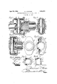
- Fig. 1 is a longitudinal sectional view of a universal joint of the character described in said Flick patent, with my novel guide and. protector applied thereto.
- Fig. 2 is a sectional view thereof in the plane of the pin. 'A
- Fig. 3 isv a sectional view of a joint .such as may e used in a Ford transmission.
- Figs. 4 and 5 are opposite end views of the socketed casing member shown in Fig. 3.
- Figs. 6 and 7 are respectively top and end views of ⁇ one of the guides detached, and
- Fig. 8 is a View of one of thecomplemental halves of the guide.
- the type of joint illustrated in Figs. 1 and 2 comprises a shaft member v2 having a ball head 2a transixed by'a pin 2b on whose ends, at opposite sides of the ball head, are mounted rollers or balls 3.
- the ballhead 2a and balls 3 are entered into one member (4) of a casing preferably composed of two separable members 4 and 5 as shown in the drawings.
- Part 4 of the casing is provided with an axial bere 4a, slightly larger in diameter than the ball head 2a, and at 'diametrically opposite sides of bore 4a with slots 4b which open at their inner sides into the outer sides of bore 4a, as shown.
- the head 2a is entered in bore 4a and balls 3 enter the slots 4b as shown.
- the member 4 is open at its outer end, through which the shaft 2 enters, and itsl inner end is provided withv a flange 4c which is attached to a corresponding flange 'on the other casing member 5 which is formed on or keyed to a shaft 10.
- the member 5 is provided with a recess adjacent the inner .end of the shaftlO for the accommodation of an expansion spring 7 which is placed in the casing between the inner end of the shaft 10 and the ball head 2a of the shaft 2.
- the improved guide comprises an approxi- .mate cylindric tubular body whose exterior diameter preferably corresponds with the in- 1100 ternal diameter of bore 4a, and which is preferably somewhat longer than the ball.
- the guide is preferably divided into two complemental sections or halves 1, on a plane extending axially .and longitudinally of the guide; the opposed halves are duplicates of each other and when put together form a complete cylindric tubulary body.
- Each half has a parti-spherical recess 1a in its inner face Whose curvature corresponds with the exterior curvature of the ball head 2a; and at the end adjacent the shaft 2, the bore of the body is outwardly flared as at 1b to allow radial movements or swing of the shaft 2.
- the body has a projecting flange 1c which is preferably recessed, as at 1d, for the reception of a circular retaining spring ring 11 which holds the parts of the body together and prevents them disengaging the head when the head and body are withdrawn from the bore 4a.
- the body is also provided with diametrically opposite slots 1e to permit the pin 2b to pass therethrough.
- the novel guide may be made of cast or wrought or pressed metal, and when engaged with the head will remain in engagement therewith, and the ball head can swing or turn freely in all directions within the guide.
- the guide In the form shown in Figs. 1 and 2 the guide is capable of longitudinal sliding movements in the bore 4a and will under the action of spring 7 follow up the. ball head in any longitudinal movement thereof in the casing.
- the spring 7 is engaged with the flange 1c and the pressure of said spring is transmitted through the guide to the ball head 2a; and while the ball head can rock within the protector its rocking motions will not be transmitted to the spring 7 nor can the spring chafe or bind on the head.
- the guide thus protects the ball head from wear by contact with the spring, keeps the spring in exact alignment with the axis of bore 4a, prevents chattering of the spring, and enhances the durability and efficiency of the joint.
- the casing member 4a has a bore 4a for the reception of the guide l, and diametrically opposite recesses 4b at opposite sides of the guide 4a for engagement of balls 3.
- the casing member 4a may be splined to the shaft 10 as indicated in the drawings.
- the shaft 2 has a ball head 2a, transfixed by a pin 2b carrying the balls 3 which engage the recesses 4bin the casing member 4m as shown in Fig. 1.
- the ide 1 forms a socket or bearing for the ball head within the casing member 4m as is obvious, and prevents cutting, chaing or b'inding of thehead on the edges of the recesses 4b with which the balls 3 are engaged.
- a guide adapted to be placed between the ball head of the shaft member of the oint and the casing member thereof; said guide comprising similar complemental halves and having diametrically opposite parti-spherical recesses engaging the ball head and retaining the guide in operative engagement therewith, the exterior portions of the halves of the guide being slidably fitted inthe boreof the casing member of the joint.
- a guide for the purpose specified comprising abody formed of similar complemental halves, each half having an exterior cylindric portion adapted to engage the bore in the casing member in which the guide is entered, an interior parti-spherical recess adapted to engage the ball head of the joint, a flange at one end for engagement of a retaining member, and diametrically opposite slots for accommodation of the pin on the ball head.
- a guide adapted to be placed between the ball head of the shaft member of the joint and the casing member thereof; said guide having diametrically opposite parti-spherical recesses engaging diametrically opposite portions of the said ball head and retaining the.
- a guide adapted to engage the ball head of the shaft member of the joint, said guide having diametrically opposite partispherical recesses engaging diametrically opposite portions of the ball head and retaining the guide in operative engagement therewith, and having an exterior portion slidably engaging the bore in the joint casing; said guide being longitudinally divided into similar halves each having a flange at one end for engagement of retaining means.
- a guide formed of similar complemental members and having a longitudinal bore to accommodate the shaft, diametrically opposite parti-spherical recesses for engagement -with the ball head of the Chaft, a projecting flange at one end of the bore for-the accommodation of a retaining spring, the other end of the bore being ared to. permit oscillatory movements of the shaft when the ball head is engaged with the guide, and diametrically opposite Open slots to accomodate the pin transxing the head; the exterior of the guide being shaped to engage the bore of the joint casing.
- a universal joint 5 comprising a casing having an axial bore and diametrically opposite slots opening into the bore, a shaft entering the casing and having a ball head on its inner end engaging said bore and members mounted on the ball head and respectively entered in said slots; a guide adapted to engage the ball head of the shaft member of the joint, and having diametrically opposite parti-spherical recesses engaging the ball head and retaining the guide in opery; ative engagement therewith.
- a universal joint comprising a casing having an axial bore and diametrically opposite slots opening into the bore, a shaft entering the casing and having a ball head on its inner end'engaging said bore, and members mounted on the ball head and respectively entered in said slots; a guide adapted to engage the ,ball head of the shaft member of the joint, said guide having diametrically opposite parti-spherical recesses engaging diametrically opposite portions of the ball head and retaining the guide in operative engagement therewith, and having an exterior portion slidably engaging the bore 3? in the casing; said guide being longitudinally divided into similar halves,
- a universal joint l comprising a casing having an axial bore and diametrically opposite slots opening into the bore, a shaft entering the casing and having a ball head on its inner end engaging said bore, and members mounted on the ball head and respectively entered in said slots; a guide ⁇ engaging the ball head and comprising a body o formed of similar complemental halves, each half having an exterior cylindric portion adapted to engage the bore in the casing, an
Landscapes
- Engineering & Computer Science (AREA)
- General Engineering & Computer Science (AREA)
- Mechanical Engineering (AREA)
- Pivots And Pivotal Connections (AREA)
Description
E April 19, 1932. A. A. WARNER GUIDE AND PROTECTOR FOR UNIVERSAL JOINTS, ETC
Filed May 1&1,` 1950 Patented Apr. 19, 1932 UNITED STATES PATENT OFFICE ARCHIBALD A. YWARNER, ROYAL OAK, MICHIGAN, ASSIGNOR TO THE UNIVERSAL PRODUCTS C0., INC., OF DEARBORN, MICHIGAN, A CORPORATION OF DELAWARE GUIDE AND PROTECTOR FOR UNIVERSAL JOINTS, ETC.
Application led May 14, 1930. Serial No. 452,487.
This invention is a novel improvement in so-.called ball head protectors and spring guides for use in universal joints, particularly such joints as are employed in automobile transmission mechanisms such as shown in patent to J. B. Flick No. 1,512,840, dated October 21, 1924, but the invention is adaptable to various forms of joints of that type in which .one member has a spherical .or ball shaped head through which passes a pin upon which arerotatably mounted balls or rollers that engage corresponding guides or recesses in a member attached to another shaft; one of the shafts transmitting rotative movement to -the other through the interengagement of the balls and grooves of the respective members. For the sake of brevity I will hereinafter refer to the combined guide and protector vby the inclusive term guide.
In the accompanying drawings I have shown the guide applied to a universal joint such as shown in the said Flick patent, and also applied to a transmission coupling such -as may be used in a Ford.
One object of the present invention is to provide a guide which will Y have av larger area of surface Contact with the ball head, and which when fitted thereto will remain in constant engagement therewith, said guide having diametrically opposite parti-spherical recesses engagingv diametrically opposite sides of the head; whereby the guide andhead will be kept constantly in engagement whether or not there is any spring-engaging the guide, or should the spring engaging the guide break.
A further object is to provide` a guide which can be made ofy rod metal, or cast or pressed, and made in complemental parts 40 which can be very easily and readily assem-k bled in operative relation with the ball yhead and the casing in which thehead is entered.
Other minor objects of the invention will be hereinafter set lforth.
I will describe the invention with reference to the aceompanying'drawings which however are to be considered as merely exemplifying applications of the invention and not as limiting its use; and an understanding there- 50 of will enable others to adopt and use the invention in connection with other joints, or other applications in the art. The claims summarize the novel features of construe,- tion and novel combinationsv of parts for which protection is desired.
In said drawings:
Fig. 1 is a longitudinal sectional view of a universal joint of the character described in said Flick patent, with my novel guide and. protector applied thereto.
Fig. 2 is a sectional view thereof in the plane of the pin. 'A
Fig. 3 isv a sectional view of a joint .such as may e used in a Ford transmission.
Figs. 4 and 5 are opposite end views of the socketed casing member shown in Fig. 3.
Figs. 6 and 7 are respectively top and end views of^one of the guides detached, and
Fig. 8 is a View of one of thecomplemental halves of the guide. v
The type of joint illustrated in Figs. 1 and 2 comprises a shaft member v2 having a ball head 2a transixed by'a pin 2b on whose ends, at opposite sides of the ball head, are mounted rollers or balls 3.` The ballhead 2a and balls 3 are entered into one member (4) of a casing preferably composed of two separable members 4 and 5 as shown in the drawings. Part 4 of the casing is provided with an axial bere 4a, slightly larger in diameter than the ball head 2a, and at 'diametrically opposite sides of bore 4a with slots 4b which open at their inner sides into the outer sides of bore 4a, as shown. The head 2a is entered in bore 4a and balls 3 enter the slots 4b as shown.
The member 4 is open at its outer end, through which the shaft 2 enters, and itsl inner end is provided withv a flange 4c which is attached to a corresponding flange 'on the other casing member 5 which is formed on or keyed to a shaft 10.
The member 5 is provided with a recess adjacent the inner .end of the shaftlO for the accommodation of an expansion spring 7 which is placed in the casing between the inner end of the shaft 10 and the ball head 2a of the shaft 2.
The improved guide comprises an approxi- .mate cylindric tubular body whose exterior diameter preferably corresponds with the in- 1100 ternal diameter of bore 4a, and which is preferably somewhat longer than the ball. The guide is preferably divided into two complemental sections or halves 1, on a plane extending axially .and longitudinally of the guide; the opposed halves are duplicates of each other and when put together form a complete cylindric tubulary body. Each half has a parti-spherical recess 1a in its inner face Whose curvature corresponds with the exterior curvature of the ball head 2a; and at the end adjacent the shaft 2, the bore of the body is outwardly flared as at 1b to allow radial movements or swing of the shaft 2. At the opposite end the body has a projecting flange 1c which is preferably recessed, as at 1d, for the reception of a circular retaining spring ring 11 which holds the parts of the body together and prevents them disengaging the head when the head and body are withdrawn from the bore 4a. The body is also provided with diametrically opposite slots 1e to permit the pin 2b to pass therethrough.
The novel guide may be made of cast or wrought or pressed metal, and when engaged with the head will remain in engagement therewith, and the ball head can swing or turn freely in all directions within the guide. In the form shown in Figs. 1 and 2 the guide is capable of longitudinal sliding movements in the bore 4a and will under the action of spring 7 follow up the. ball head in any longitudinal movement thereof in the casing. The spring 7 is engaged with the flange 1c and the pressure of said spring is transmitted through the guide to the ball head 2a; and while the ball head can rock within the protector its rocking motions will not be transmitted to the spring 7 nor can the spring chafe or bind on the head. The guide thus protects the ball head from wear by contact with the spring, keeps the spring in exact alignment with the axis of bore 4a, prevents chattering of the spring, and enhances the durability and efficiency of the joint.
In the simple joint shown in Fig. 3 there is not supposed to be any endwise play between the shaft sections 2 and 10 and therefore no spring as 7 is required. In such oint the casing member 4a: has a bore 4a for the reception of the guide l, and diametrically opposite recesses 4b at opposite sides of the guide 4a for engagement of balls 3. The casing member 4a: may be splined to the shaft 10 as indicated in the drawings. The shaft 2 has a ball head 2a, transfixed by a pin 2b carrying the balls 3 which engage the recesses 4bin the casing member 4m as shown in Fig. 1. The ide 1 forms a socket or bearing for the ball head within the casing member 4m as is obvious, and prevents cutting, chaing or b'inding of thehead on the edges of the recesses 4b with which the balls 3 are engaged.
When the parts are assembled the space between the ball head 2a and the shaft 10 should be lled with grease so that all the moving parts will beproperly lubricated. The operation of the parts will be obvious from the drawings and the foregoing description.
I claim 1. For a universal joint of the character specified; a guide adapted to be placed between the ball head of the shaft member of the oint and the casing member thereof; said guide comprising similar complemental halves and having diametrically opposite parti-spherical recesses engaging the ball head and retaining the guide in operative engagement therewith, the exterior portions of the halves of the guide being slidably fitted inthe boreof the casing member of the joint.
2. A guide for the purpose specified; comprising abody formed of similar complemental halves, each half having an exterior cylindric portion adapted to engage the bore in the casing member in which the guide is entered, an interior parti-spherical recess adapted to engage the ball head of the joint, a flange at one end for engagement of a retaining member, and diametrically opposite slots for accommodation of the pin on the ball head.
3. For a joint of the character specified; a guide adapted to be placed between the ball head of the shaft member of the joint and the casing member thereof; said guide having diametrically opposite parti-spherical recesses engaging diametrically opposite portions of the said ball head and retaining the.
guide in operative engagement therewith, and also having an exterior portion slidably litted in the bore of the joint casing, said guide being longitudinally divided into similar halves.
4. In a universal joint of the character specified; a guide adapted to engage the ball head of the shaft member of the joint, said guide having diametrically opposite partispherical recesses engaging diametrically opposite portions of the ball head and retaining the guide in operative engagement therewith, and having an exterior portion slidably engaging the bore in the joint casing; said guide being longitudinally divided into similar halves each having a flange at one end for engagement of retaining means.
5. For a universal joint; a guide formed of similar complemental members and having a longitudinal bore to accommodate the shaft, diametrically opposite parti-spherical recesses for engagement -with the ball head of the Chaft, a projecting flange at one end of the bore for-the accommodation of a retaining spring, the other end of the bore being ared to. permit oscillatory movements of the shaft when the ball head is engaged with the guide, and diametrically opposite Open slots to accomodate the pin transxing the head; the exterior of the guide being shaped to engage the bore of the joint casing.
6. In combination with a universal joint 5 comprising a casing having an axial bore and diametrically opposite slots opening into the bore, a shaft entering the casing and having a ball head on its inner end engaging said bore and members mounted on the ball head and respectively entered in said slots; a guide adapted to engage the ball head of the shaft member of the joint, and having diametrically opposite parti-spherical recesses engaging the ball head and retaining the guide in opery; ative engagement therewith.
7. 'In combination with a universal joint comprising a casing having an axial bore and diametrically opposite slots opening into the bore, a shaft entering the casing and having a ball head on its inner end'engaging said bore, and members mounted on the ball head and respectively entered in said slots; a guide adapted to engage the ,ball head of the shaft member of the joint, said guide having diametrically opposite parti-spherical recesses engaging diametrically opposite portions of the ball head and retaining the guide in operative engagement therewith, and having an exterior portion slidably engaging the bore 3? in the casing; said guide being longitudinally divided into similar halves,
8. In combination with a universal joint l comprising a casing having an axial bore and diametrically opposite slots opening into the bore,a shaft entering the casing and having a ball head on its inner end engaging said bore, and members mounted on the ball head and respectively entered in said slots; a guide `engaging the ball head and comprising a body o formed of similar complemental halves, each half having an exterior cylindric portion adapted to engage the bore in the casing, an
' interior arti-spherical recess adapted to engage the all head of the joint, a flange at one end for engagement of a retaining member, and a part-slot at diametrically opposite sides of the bore to accommodate the pin on the ball head.
vARCHIBALD WARNER.
Priority Applications (1)
| Application Number | Priority Date | Filing Date | Title |
|---|---|---|---|
| US452487A US1854873A (en) | 1930-05-14 | 1930-05-14 | Guide and protector for universal joints, etc. |
Applications Claiming Priority (1)
| Application Number | Priority Date | Filing Date | Title |
|---|---|---|---|
| US452487A US1854873A (en) | 1930-05-14 | 1930-05-14 | Guide and protector for universal joints, etc. |
Publications (1)
| Publication Number | Publication Date |
|---|---|
| US1854873A true US1854873A (en) | 1932-04-19 |
Family
ID=23796649
Family Applications (1)
| Application Number | Title | Priority Date | Filing Date |
|---|---|---|---|
| US452487A Expired - Lifetime US1854873A (en) | 1930-05-14 | 1930-05-14 | Guide and protector for universal joints, etc. |
Country Status (1)
| Country | Link |
|---|---|
| US (1) | US1854873A (en) |
-
1930
- 1930-05-14 US US452487A patent/US1854873A/en not_active Expired - Lifetime
Similar Documents
| Publication | Publication Date | Title |
|---|---|---|
| US2813409A (en) | Universal coupling | |
| US2441052A (en) | Coupling that compensates for axial displacement of shafts connected thereby | |
| WO2015141834A1 (en) | Tripod-type constant velocity joint | |
| US2911805A (en) | Universal joint | |
| US2614405A (en) | Power take-off coupling | |
| US2006026A (en) | Universal joint | |
| US2921451A (en) | Constant velocity universal joint structure | |
| US2620640A (en) | Flexible coupling | |
| US2255762A (en) | Constant velocity universal joint | |
| US1524161A (en) | Universal joint | |
| US1854873A (en) | Guide and protector for universal joints, etc. | |
| US2171999A (en) | Universal joint | |
| US1707530A (en) | Universal coupling | |
| US2057875A (en) | Universal joint | |
| US1508653A (en) | Universal joint | |
| US2042513A (en) | Double universal joint | |
| US1543575A (en) | Housing for universal joints | |
| US1947046A (en) | Universal joint | |
| US1512840A (en) | Combined guide and protector for use in universal joints | |
| US1717481A (en) | Lubricant retainer and dust guard for universal joints | |
| US1583291A (en) | Propeller shaft | |
| US2263279A (en) | Joint for the connection of shafts | |
| US3045456A (en) | Homokinetic universal joint | |
| GB149504A (en) | Improvements in or relating to universal joints or couplings for transmitting rotarymotion | |
| US2487485A (en) | Universal coupling |