US1854872A - Manufacture of sheets or slabs - Google Patents
Manufacture of sheets or slabs Download PDFInfo
- Publication number
- US1854872A US1854872A US246345A US24634528A US1854872A US 1854872 A US1854872 A US 1854872A US 246345 A US246345 A US 246345A US 24634528 A US24634528 A US 24634528A US 1854872 A US1854872 A US 1854872A
- Authority
- US
- United States
- Prior art keywords
- oven
- sheets
- sheet
- machine
- manufacture
- Prior art date
- Legal status (The legal status is an assumption and is not a legal conclusion. Google has not performed a legal analysis and makes no representation as to the accuracy of the status listed.)
- Expired - Lifetime
Links
- 238000004519 manufacturing process Methods 0.000 title description 10
- 239000000463 material Substances 0.000 description 15
- 238000001035 drying Methods 0.000 description 10
- 239000004033 plastic Substances 0.000 description 10
- 229920003023 plastic Polymers 0.000 description 10
- 238000000034 method Methods 0.000 description 4
- 208000027418 Wounds and injury Diseases 0.000 description 2
- 230000001413 cellular effect Effects 0.000 description 2
- 230000006378 damage Effects 0.000 description 2
- 238000010438 heat treatment Methods 0.000 description 2
- 208000014674 injury Diseases 0.000 description 2
- 239000000203 mixture Substances 0.000 description 2
- 239000007787 solid Substances 0.000 description 2
- 238000009966 trimming Methods 0.000 description 2
- 235000019738 Limestone Nutrition 0.000 description 1
- 239000004115 Sodium Silicate Substances 0.000 description 1
- 230000015572 biosynthetic process Effects 0.000 description 1
- 238000009435 building construction Methods 0.000 description 1
- 239000004566 building material Substances 0.000 description 1
- 239000000470 constituent Substances 0.000 description 1
- OYFJQPXVCSSHAI-QFPUQLAESA-N enalapril maleate Chemical compound OC(=O)\C=C/C(O)=O.C([C@@H](C(=O)OCC)N[C@@H](C)C(=O)N1[C@@H](CCC1)C(O)=O)CC1=CC=CC=C1 OYFJQPXVCSSHAI-QFPUQLAESA-N 0.000 description 1
- 239000000945 filler Substances 0.000 description 1
- 239000012634 fragment Substances 0.000 description 1
- 239000004615 ingredient Substances 0.000 description 1
- 229910052500 inorganic mineral Inorganic materials 0.000 description 1
- 239000006028 limestone Substances 0.000 description 1
- 239000011707 mineral Substances 0.000 description 1
- 230000005855 radiation Effects 0.000 description 1
- 238000000926 separation method Methods 0.000 description 1
- NTHWMYGWWRZVTN-UHFFFAOYSA-N sodium silicate Chemical compound [Na+].[Na+].[O-][Si]([O-])=O NTHWMYGWWRZVTN-UHFFFAOYSA-N 0.000 description 1
- 229910052911 sodium silicate Inorganic materials 0.000 description 1
Images
Classifications
-
- B—PERFORMING OPERATIONS; TRANSPORTING
- B28—WORKING CEMENT, CLAY, OR STONE
- B28B—SHAPING CLAY OR OTHER CERAMIC COMPOSITIONS; SHAPING SLAG; SHAPING MIXTURES CONTAINING CEMENTITIOUS MATERIAL, e.g. PLASTER
- B28B1/00—Producing shaped prefabricated articles from the material
- B28B1/52—Producing shaped prefabricated articles from the material specially adapted for producing articles from mixtures containing fibres, e.g. asbestos cement
-
- B—PERFORMING OPERATIONS; TRANSPORTING
- B28—WORKING CEMENT, CLAY, OR STONE
- B28B—SHAPING CLAY OR OTHER CERAMIC COMPOSITIONS; SHAPING SLAG; SHAPING MIXTURES CONTAINING CEMENTITIOUS MATERIAL, e.g. PLASTER
- B28B11/00—Apparatus or processes for treating or working the shaped or preshaped articles
-
- B—PERFORMING OPERATIONS; TRANSPORTING
- B28—WORKING CEMENT, CLAY, OR STONE
- B28B—SHAPING CLAY OR OTHER CERAMIC COMPOSITIONS; SHAPING SLAG; SHAPING MIXTURES CONTAINING CEMENTITIOUS MATERIAL, e.g. PLASTER
- B28B11/00—Apparatus or processes for treating or working the shaped or preshaped articles
- B28B11/24—Apparatus or processes for treating or working the shaped or preshaped articles for curing, setting or hardening
-
- B—PERFORMING OPERATIONS; TRANSPORTING
- B28—WORKING CEMENT, CLAY, OR STONE
- B28B—SHAPING CLAY OR OTHER CERAMIC COMPOSITIONS; SHAPING SLAG; SHAPING MIXTURES CONTAINING CEMENTITIOUS MATERIAL, e.g. PLASTER
- B28B19/00—Machines or methods for applying the material to surfaces to form a permanent layer thereon
- B28B19/0092—Machines or methods for applying the material to surfaces to form a permanent layer thereon to webs, sheets or the like, e.g. of paper, cardboard
Definitions
- UPSON OI LOCKPORT, NEW YORK, ASSIGNOR TO THE UPSON COMPANY,
- My present invention relates to the manufacture of sheets or slabs, particularly when composed in whole or in part of material originally in the plastic state, and it has for its object an improved process or method, and a simple compact and efficient machine for producing a product of this kind.
- a further object of the invention is to produce in an economical manner a high grade of wallboard for building constructions, and similar sheets, my invention contemplating their production as a continuous forming operation.
- the improvements are directed in part toward the provision of means for preliminarily hardening the product after it issues from the forming element, so that it can be safely and conveniently manipulated without injury in passing it to a drying and curing medium.
- Fig. 1 is a side view of the feed and forming end of the machine broken away, and showing one embodiment of my invention
- Fig. 2 is a side view of the intermediate portion of the machine broken away at both ends and forming a continuation of Fig. 1;
- Fig. 3 is a side View of the delivery end of the machine broken away at one end, and forming a continuation of Fig. 2;
- Fig. 4 is a top view broken away of the portions of the machine shown in Figs. 1, 2 and 3, but condensed;
- Fig. 5 is an enlarged fragmentary sectional view of a portion of the platen bed with a fragment of the product in formation therebetween;
- Fig.6 is an enlarged section on the line 66 of Fig. 4;
- Fig. 7 is an enlarged section on the line 77 of Fig 4;
- Fig. 8 is an enlarged section on the line 8-8 of Fig. 4;
- Fig. 9 is a side view of the feed and forming end of a modified embodiment of tion broken away;
- Fig. 10 is a broken side view of an intermediate continuation of the oven shown at the top of Fig. 9, the two views being connected B to B;
- Fig. 11 is a broken side view of the intermediate portion of the lower platen section of Fig. 9, being connected A to A to the last mentioned figure and Fig. 12 is a broken continuation of both Figs. 10 and 11 continued B to B and A to A, and showing the delivery end of the machine.
- the -present machine and method in the two embodiments shown has been specially designed for the manufacture of a special wallboard, preferably composed of two outer paper facings, or liners, as they are called, and a cellular fire-resisting and insulating mineral bod of substantial thickness therebetween.
- a mixture having as the principal ingredients sodium silicate and a filler of finely comminuted or powdered dolomitic limestone provides a suitable body between the paper walls for the purposes of producing such a 1product.
- Such a mixture is intumescent in c aracter, and puffs up into a cellular or s onge-like consistency when confined and subjected to a proper de cc of heat. It can later be hardened an dried and assumes a solid texture, in which state it is hard and relatively stiff without being brittle.
- My invention contemplates producing such a board continuously in a moving strip or sheet that is finally cut-into lengths.
- I provide a supply of paper consisting of two strips which are brought together one upon another and a suitable amount of theplastic material fed between them. This laminated the invenmass is passed between a air of upper and lower heated platens which presents smooth walls of considerable extent and whose separation regulates the thickness of the product. These platens are heated by steam or otherwise, but if by steam at a pressure of from 125 to 200 pounds, the s eed of assage of the material between them einga actor.
- a feeding device referably in the form of a pair of driven eed rolls, which draw the material all the way from its source at the feed end of the machine through the platens, past a slitting and trimming device located between the p atens and the hardening oven, and through the hardening oven.
- the sheet may be severed by a suitable cutting device into the desired lengths.
- This oven also contains heated air, preferably in circulation.
- the sheet becomes a finished product, and is cooled and subject to safe manipulation.
- I preferably connect up the hot air supply so that the current therefrom heats both ovens serially, and I also prefer to arrange the platens and ovens in such manner that heat is conserved, and wasteful radiation avoided.
- 1 indicates a suitable bed or base frame having at the feed end thereof paper rolls 2 and 3 for the supply of liners.
- the plastic material is fed from a conventionally shown hopper 4 between rolls 5 and 6 beneath it.
- the paper from roll 2 passes over the top of roll 6 and thence around and under it in a reverse direction.
- the paper from roll 3 passes over roll 5 and thence under roll 6 continuing in the same direction, so that the plastic material is deposited in suitable quantities between thev two liners X and Y, and is held between them as the three-ply mass passes into the platen section.
- the platens of this section are made of a plurality of upper units 7 and lower units 8 spaced apart for the desired thickness, and the section is shown collectively in Figs. 1 and 2.
- Figs. 1 and 2 As the sheet emerges as shown at XY from the end of this section, its'edges are trimmed by suitable trimming devices 9, and it may be slit by another cutter indicated conventionally at 10 in Fig. 4 into two strips, if desired. It then immediately passes into the oven 11 shown collectively in -1gs. 2 and 3, where the hardening takes place.
- the feed rollers 12 suitably driven, which pull the sheet through all of the travel above described to this point.
- a continuation of the said lower ramp 15 within the processing or drying and curing oven 18 carries the sheet forwardly again through that oven, which is located immediately below the platen bed preferably in such manner that one tends to warm the other. Emerging at the forward end of oven 18 the sheet or board is again reversed by falling upon an incline of ramp 19 and carried on the latter back through the drying oven again. Its upper and lower paths in a reverse direction are shown in section in Fig. 6, 20 indicating 'a bafile between the two ramps.
- This lower ramp 19 issues from the opposite end of the oven, and finally delivers the board as a finished product at the rear end of the machine.
- the hot air supply for the oven is best shown in Figs. 3 and 4, and consists of an intake conduit 21 connected with a suitable heater and blower (not shown) which delivers into the drying oven 18. From thence it passes through a connection 22 into a conduit 23 and part of it goes through a connection 24 into the hardening oven 11, from which it emerges, all as shown by the arrows, at 25.
- This exhaust may be used in preliminarily treating some of the materials, or may go back to the heater. The remainder of the air current continues to traverse the conduit 1 23 emerging at 26, at which point it may be led back to the heater.
- Figs. 9, 10, 11 and 12 I have shown a modified form-of machinery which, up to the severing points 13, is substantially the same as the first embodiment.
- the board in this case passes up an inclined ramp 14a (Fig. 12) onto a shifting or tilting ramp 15a, the two positions of which are shown in full and dotted lines.
- This ramp carries suitably driven rollers, and delivers a length of board first to a lower ramp conveyer 16a in the dryer 18. It is reversed at the opposite end onto an upper ramp conveyer 19a by another tilting ramp 19?) as shown in Fig. 9. It is delivered at the rear end onto the platform 27, and there disposed of.
- a machine for forming sheets from plastics the combination with a pair of heated platen walls of substantial area, of means for feeding plastic material between said walls, a hardening oven associated with the platens and closely adjacent thereto, a drying and curing oven, and a feeding device located between the two ovens adapted to draw the hardened sheet from the first and to move it into the second, one of said ovens being relatively arranged to overlie the other.
- a machine for forming sheets from plastics the combination with a pair of heated platen walls of substantial area, of means for feeding plastic material between said walls, a hardening oven associated with the platens and closely adjacent-thereto, a drying and curingoven, and a feeding device located between the two ovens adapted to draw the hardenedsheet from the first and K to move it into the second, one of said ovens and the platens being relatively arranged to overlie each other.
- Apparatus for forming sheets of building material substantially continuously comprising means for forming a continuous strip of material, platen means for confining and heating a moving strip of said material, oven means for additionally heating said material, mechanism for pulling a continuous strip of said material through said platen means and oven means, severing mechanism beyond said pulling mechanism for severing said continuous strip into a plurality of separate panels, a treating chamber arranged in overlapping relation to said oven means so that the total length of said apparatus is reduced,
Landscapes
- Engineering & Computer Science (AREA)
- Chemical & Material Sciences (AREA)
- Ceramic Engineering (AREA)
- Mechanical Engineering (AREA)
- Structural Engineering (AREA)
- Manufacturing & Machinery (AREA)
- Devices For Post-Treatments, Processing, Supply, Discharge, And Other Processes (AREA)
Description
April 19, 1932. c. A. UPSON MANUFACTURE OF SHEETS OR SLABS Filed Jan. 12, 1928 ENTOR I l I luv Z25 I so a .x 4w \-H- gmfi A Y N N WN Q W w Q 3 Q April 19, 1932. c. A. uPsoN MANUFACTURE OF SHEETS OR SLABS Filed Jan. 12, 1928 April 19, 19.32.
:i: E y T 1;: m R1 I} I I5 i] I i M :5:1 I Q n: a :5: l M 5 i: :5 1:: i i: I: ::5: 5; E: ii ii :i w :iii i :I j H :i f ii :i ii: 4 5: 1: i
:i: 5 iii! R? L 1: I s :l R x: a: 5 1:5] I g I} I N :l 1 w :5: Q2 I #1:: v {I I: I v I: I: N :I ll H \O H I- *0 'l I' H 1: :l I N "n: v.
c. A. UPSON MANUFACTURE OF SHEETS 0R SLABS Filed Jan. 12, 1928 3 Sheets-Sheet 5 Patented Apr. 19, 1932 {UNITED STATES CHARLES A.
PATENT OFFICE.
UPSON, OI LOCKPORT, NEW YORK, ASSIGNOR TO THE UPSON COMPANY,
01 LOCKPORT, NEW YORK, A CORPORATION OF NEW YORK MANUFACTURE OF SHEETS OR 8151538 Application filed January 12, 1928. Serial No. 246,345.
My present invention relates to the manufacture of sheets or slabs, particularly when composed in whole or in part of material originally in the plastic state, and it has for its object an improved process or method, and a simple compact and efficient machine for producing a product of this kind. A further object of the invention is to produce in an economical manner a high grade of wallboard for building constructions, and similar sheets, my invention contemplating their production as a continuous forming operation. The improvements are directed in part toward the provision of means for preliminarily hardening the product after it issues from the forming element, so that it can be safely and conveniently manipulated without injury in passing it to a drying and curing medium.
To these and other ends the invention re- 7 sides in certain improvements and combinations of parts, all as will be hereinafter more fully described, the novel features being pointed out in the claims at the end of the specification.
In the drawings:
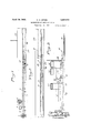
Fig. 1 is a side view of the feed and forming end of the machine broken away, and showing one embodiment of my invention;
Fig. 2 is a side view of the intermediate portion of the machine broken away at both ends and forming a continuation of Fig. 1;
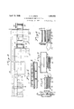
Fig. 3 is a side View of the delivery end of the machine broken away at one end, and forming a continuation of Fig. 2;
Fig. 4 is a top view broken away of the portions of the machine shown in Figs. 1, 2 and 3, but condensed;
Fig. 5 is an enlarged fragmentary sectional view of a portion of the platen bed with a fragment of the product in formation therebetween;
Fig.6 is an enlarged section on the line 66 of Fig. 4;
Fig. 7 is an enlarged section on the line 77 of Fig 4;
Fig. 8 is an enlarged section on the line 8-8 of Fig. 4;
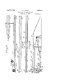
50 Fig. 9 is a side view of the feed and forming end of a modified embodiment of tion broken away;
Fig. 10 is a broken side view of an intermediate continuation of the oven shown at the top of Fig. 9, the two views being connected B to B;
Fig. 11 is a broken side view of the intermediate portion of the lower platen section of Fig. 9, being connected A to A to the last mentioned figure and Fig. 12 is a broken continuation of both Figs. 10 and 11 continued B to B and A to A, and showing the delivery end of the machine.
Similar reference numerals throughout the several views indicate the same arts.
Although its advantages and unctions are not necessarily limited to such ,use, the -present machine and method in the two embodiments shown, has been specially designed for the manufacture of a special wallboard, preferably composed of two outer paper facings, or liners, as they are called, and a cellular fire-resisting and insulating mineral bod of substantial thickness therebetween. t has been discovered that a mixture having as the principal ingredients sodium silicate and a filler of finely comminuted or powdered dolomitic limestone provides a suitable body between the paper walls for the purposes of producing such a 1product. Such a mixture is intumescent in c aracter, and puffs up into a cellular or s onge-like consistency when confined and subjected to a proper de cc of heat. It can later be hardened an dried and assumes a solid texture, in which state it is hard and relatively stiff without being brittle. My invention contemplates producing such a board continuously in a moving strip or sheet that is finally cut-into lengths.
To first describe in eneral the mode of manufacturing such a oard in accordance with my invention, and assuming that a board with two facings or liners is to be made (though one liner alone may be used or none at all resulting in a solid plastic product) I provide a supply of paper consisting of two strips which are brought together one upon another and a suitable amount of theplastic material fed between them. This laminated the invenmass is passed between a air of upper and lower heated platens which presents smooth walls of considerable extent and whose separation regulates the thickness of the product. These platens are heated by steam or otherwise, but if by steam at a pressure of from 125 to 200 pounds, the s eed of assage of the material between them einga actor. From the platens the sheet passes in a formative and relatively soft state immediately into a closely adjacent hardening oven where it is treated by direct contact with a heated gas. I prefer to use hot air. In this oven the sheet hardens and it becomes set sufiiciently so that it can be manipulated without dan er of injury or distortion. I am, therefore, a le to place and'do place just beyond this hardening oven a feeding device referably in the form of a pair of driven eed rolls, which draw the material all the way from its source at the feed end of the machine through the platens, past a slitting and trimming device located between the p atens and the hardening oven, and through the hardening oven. Just beyond the feed rollers the sheet may be severed by a suitable cutting device into the desired lengths. The sheet, thou h severed, next passes and is pushed by the eed rollers into what is termned a processing oven for drying and curing. This oven also contains heated air, preferably in circulation. Upon emerging from this drying oven the sheet becomes a finished product, and is cooled and subject to safe manipulation. I preferably connect up the hot air supply so that the current therefrom heats both ovens serially, and I also prefer to arrange the platens and ovens in such manner that heat is conserved, and wasteful radiation avoided.
Referring more particularly to the drawings, and to Fig. 1 thereof, 1 indicates a suitable bed or base frame having at the feed end thereof paper rolls 2 and 3 for the supply of liners. The plastic material is fed from a conventionally shown hopper 4 between rolls 5 and 6 beneath it. The paper from roll 2 passes over the top of roll 6 and thence around and under it in a reverse direction. The paper from roll 3 passes over roll 5 and thence under roll 6 continuing in the same direction, so that the plastic material is deposited in suitable quantities between thev two liners X and Y, and is held between them as the three-ply mass passes into the platen section.
The platens of this section are made of a plurality of upper units 7 and lower units 8 spaced apart for the desired thickness, and the section is shown collectively in Figs. 1 and 2. As the sheet emerges as shown at XY from the end of this section, its'edges are trimmed by suitable trimming devices 9, and it may be slit by another cutter indicated conventionally at 10 in Fig. 4 into two strips, if desired. It then immediately passes into the oven 11 shown collectively in -1gs. 2 and 3, where the hardening takes place. Just beyond this oven are the feed rollers 12 suitably driven, which pull the sheet through all of the travel above described to this point. The sheet is now sufficiently hard, so that it is not injured by the rollers, and so that it is pushed under a sever ing device conventionally shown at 13 in Fig. 3 on a platform 14, which cuts it into lengths, and the severed sheets go on down an inclined ramp 14 on to a reversely inclined lower ramp 15 that changes their direction. These ramps heretofore and hereinafter referred to preferably consist of a series of rolls as shown at 16, Fig. 1, some of which may be idlers, and some of which may be driven as by the sprocket gearing shown generally at 17, or all of them may be driven to keep the sheet moving by frictional contact.
A continuation of the said lower ramp 15 within the processing or drying and curing oven 18 carries the sheet forwardly again through that oven, which is located immediately below the platen bed preferably in such manner that one tends to warm the other. Emerging at the forward end of oven 18 the sheet or board is again reversed by falling upon an incline of ramp 19 and carried on the latter back through the drying oven again. Its upper and lower paths in a reverse direction are shown in section in Fig. 6, 20 indicating 'a bafile between the two ramps. This lower ramp 19 issues from the opposite end of the oven, and finally delivers the board as a finished product at the rear end of the machine.
Aside from heat conservation, the object sought in placing the ovens and platens one above another, and carrying the product baclrand forth through these at different elevations (and this is a very important advantage) is to reduce the overall length of the machine and the building which it occupies, and to render it compact and accessible as to its several elements. These board making machines are built on very large scales to make wide sheets of heavy boards, and were it not for this condensing of parts, a building hundreds of feet long would ordinarily be required.
The hot air supply for the oven is best shown in Figs. 3 and 4, and consists of an intake conduit 21 connected with a suitable heater and blower (not shown) which delivers into the drying oven 18. From thence it passes through a connection 22 into a conduit 23 and part of it goes through a connection 24 into the hardening oven 11, from which it emerges, all as shown by the arrows, at 25. This exhaust may be used in preliminarily treating some of the materials, or may go back to the heater. The remainder of the air current continues to traverse the conduit 1 23 emerging at 26, at which point it may be led back to the heater.
In Figs. 9, 10, 11 and 12, I have shown a modified form-of machinery which, up to the severing points 13, is substantially the same as the first embodiment. In this machine, however, I place the processing or drying oven 18a above the platen bed and hardening oven 11 instead of below. This prevents the close contact of the two, however, because opportunity must be had to raise and lower the upper platen, though'the machine is shortened up as before. The board in this case passes up an inclined ramp 14a (Fig. 12) onto a shifting or tilting ramp 15a, the two positions of which are shown in full and dotted lines. This ramp carries suitably driven rollers, and delivers a length of board first to a lower ramp conveyer 16a in the dryer 18. It is reversed at the opposite end onto an upper ramp conveyer 19a by another tilting ramp 19?) as shown in Fig. 9. It is delivered at the rear end onto the platform 27, and there disposed of.
It is to be understood that I contemplate my invention, including both method and machine, to be useful in the manufacture of slabs or sheets composed of other materials or constituents than those named specifically herein.
I claim as my invention:
1. In a machine for forming sheets from plastics, the combination with a pair of heated platen walls of substantial area, of means for feeding plastic material between said walls, a hardening oven associated with the platens and closely adjacent thereto, a drying and curing oven, and a feeding device located between the two ovens adapted to draw the hardened sheet from the first and to move it into the second, one of said ovens being relatively arranged to overlie the other.
2. In a machine for forming sheets from plastics, the combination with a pair of heated platen walls of substantial area, of means for feeding plastic material between said walls, a hardening oven associated with the platens and closely adjacent-thereto, a drying and curingoven, and a feeding device located between the two ovens adapted to draw the hardenedsheet from the first and K to move it into the second, one of said ovens and the platens being relatively arranged to overlie each other.
3. In a machine for forming sheets from plastics, the combination with a pair of eated means said walls, a hardening oven associated with the platens and closely adjacent thereto, a drying and curing oven, a feeding device lo cated between the two ovens adapted to draw the hardened sheet from the first and to move it into the second, a source of hot gas supply fplaten Walls of substantial area, of
or feeding plastic material between and conduits connecting the ovens therewith and with each other whereby a circulation is created and gas from one oven is driven through the other.
4. Apparatus for forming sheets of building material substantially continuously, comprising means for forming a continuous strip of material, platen means for confining and heating a moving strip of said material, oven means for additionally heating said material, mechanism for pulling a continuous strip of said material through said platen means and oven means, severing mechanism beyond said pulling mechanism for severing said continuous strip into a plurality of separate panels, a treating chamber arranged in overlapping relation to said oven means so that the total length of said apparatus is reduced,
Priority Applications (3)
| Application Number | Priority Date | Filing Date | Title |
|---|---|---|---|
| NL28914D NL28914C (en) | 1928-01-12 | ||
| US246345A US1854872A (en) | 1928-01-12 | 1928-01-12 | Manufacture of sheets or slabs |
| DEU10703D DE579719C (en) | 1928-01-12 | 1929-04-20 | Machine for the production of building panels |
Applications Claiming Priority (1)
| Application Number | Priority Date | Filing Date | Title |
|---|---|---|---|
| US246345A US1854872A (en) | 1928-01-12 | 1928-01-12 | Manufacture of sheets or slabs |
Publications (1)
| Publication Number | Publication Date |
|---|---|
| US1854872A true US1854872A (en) | 1932-04-19 |
Family
ID=22930273
Family Applications (1)
| Application Number | Title | Priority Date | Filing Date |
|---|---|---|---|
| US246345A Expired - Lifetime US1854872A (en) | 1928-01-12 | 1928-01-12 | Manufacture of sheets or slabs |
Country Status (1)
| Country | Link |
|---|---|
| US (1) | US1854872A (en) |
-
1928
- 1928-01-12 US US246345A patent/US1854872A/en not_active Expired - Lifetime
Similar Documents
| Publication | Publication Date | Title |
|---|---|---|
| US3200181A (en) | Method of and means for manufacturing padding and insulating materials comprising fibres | |
| US2366673A (en) | Method of preparing gypsum casts | |
| US2655458A (en) | Method of forming wood wool panels | |
| US1578250A (en) | Process of making plaster board | |
| US2069589A (en) | Machine for manufacturing pavements from vulcanizable materials | |
| ES491378A0 (en) | A METHOD, WITH ITS APPROPRIATE APPARATUS FOR THE MANUFACTURE OF PLASTIC PRODUCTS | |
| US1730673A (en) | Method and apparatus for producing a variegated plastic sheet | |
| US2344601A (en) | Treatment of fibrous glass | |
| BG99828A (en) | Method for the production of insulation strips of mineral fibres, plant for its manufacture and a mineral fibres insulated plate | |
| US1854872A (en) | Manufacture of sheets or slabs | |
| US1871843A (en) | Method of manufacturing tile board | |
| US2612706A (en) | Continuous manufacture of extruded clay composition bodies | |
| US2742951A (en) | Art of curling or kinking stretched filaments and forming pads therefrom | |
| US3928105A (en) | Automated apparatus and process for making match molded covering | |
| US2276083A (en) | Molded cement product and manufacture of same | |
| US2173391A (en) | Process of manufacturing fibrous products | |
| US1829802A (en) | Machine and method for making wall board | |
| KR100358071B1 (en) | The production process of hard mat cotton and the equipment | |
| US1803779A (en) | Platen support for heat processing machines | |
| US2263207A (en) | Intermittent conveyer | |
| US1973931A (en) | Shingle | |
| JP2859687B2 (en) | Ceramic plate manufacturing method | |
| US2134659A (en) | Synthetic fibrous product and process of making the same | |
| US1819199A (en) | Method of making building materials | |
| JPS6317250A (en) | Continuously manufacturing equipment for elongated ceramic sheet |