US1854869A - Gyroscopic compass - Google Patents
Gyroscopic compass Download PDFInfo
- Publication number
- US1854869A US1854869A US70346A US7034625A US1854869A US 1854869 A US1854869 A US 1854869A US 70346 A US70346 A US 70346A US 7034625 A US7034625 A US 7034625A US 1854869 A US1854869 A US 1854869A
- Authority
- US
- United States
- Prior art keywords
- compass
- damping
- latitude
- error
- weight
- Prior art date
- Legal status (The legal status is an assumption and is not a legal conclusion. Google has not performed a legal analysis and makes no representation as to the accuracy of the status listed.)
- Expired - Lifetime
Links
- 238000013016 damping Methods 0.000 description 30
- 230000010355 oscillation Effects 0.000 description 6
- 230000005484 gravity Effects 0.000 description 4
- 238000000034 method Methods 0.000 description 3
- 230000000694 effects Effects 0.000 description 2
- 241000239290 Araneae Species 0.000 description 1
- 230000001419 dependent effect Effects 0.000 description 1
- 238000010586 diagram Methods 0.000 description 1
- 230000008030 elimination Effects 0.000 description 1
- 238000003379 elimination reaction Methods 0.000 description 1
- 230000002452 interceptive effect Effects 0.000 description 1
- 239000007788 liquid Substances 0.000 description 1
- QSHDDOUJBYECFT-UHFFFAOYSA-N mercury Chemical compound [Hg] QSHDDOUJBYECFT-UHFFFAOYSA-N 0.000 description 1
- 229910052753 mercury Inorganic materials 0.000 description 1
Images
Classifications
-
- G—PHYSICS
- G01—MEASURING; TESTING
- G01C—MEASURING DISTANCES, LEVELS OR BEARINGS; SURVEYING; NAVIGATION; GYROSCOPIC INSTRUMENTS; PHOTOGRAMMETRY OR VIDEOGRAMMETRY
- G01C19/00—Gyroscopes; Turn-sensitive devices using vibrating masses; Turn-sensitive devices without moving masses; Measuring angular rate using gyroscopic effects
- G01C19/02—Rotary gyroscopes
- G01C19/34—Rotary gyroscopes for indicating a direction in the horizontal plane, e.g. directional gyroscopes
- G01C19/38—Rotary gyroscopes for indicating a direction in the horizontal plane, e.g. directional gyroscopes with north-seeking action by other than magnetic means, e.g. gyrocompasses using earth's rotation
Definitions
- This invention relates to gyroscopic compasses in which means are employed to elimie nate the error or oscillations otherwise caused when the ship on which the compass is mounted changes its speed or course. It has been found that oscillations are set up at this time by the damping factor of the compass and to overcome this it has been proposed to substantially eliminate .or greatly reduce the damping during this time.
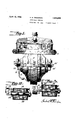
- Fig. 1 i a side elevation, with parts broken away, of the Sperry type compass with my invention appliedthereto.
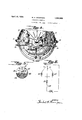
- Fig. 2 is a section of the weight-shifting device which I employ on the compass.
- Fig. 3 is acorresponding section of the modified form of weight-shifting device.
- Fig. 4 is a side elevation, partly in section, of the gyroscopic portion of the compass with my invention applied thereto.
- Fig. 5 is a detail showing the adjusting means for different latitudes.
- Fig. 6 is a simplifiedwiring diagram of my invention.
- the drawings show in simple form a standard Sperry compass consisting of the usual gyro rotor casing 1, vertical ring 2, follow-up supporting ring 3, gimbal support 4, and spider 5.
- the correction device employed on such compasses usually consists of two dials 6 and 7 the former being for latitude and the latter for ships speed.
- the gravitational factor is illustrated as a frame work 10, pivoted ,on the follow-up ring 3 on pivots 11 and 12 and carrying, in this instance, two pairs of mercury containers 13 and 14, the units of each pair being connected by pipes 15 and 16.
- the said gravitational factor is connected to the gyro case by an arm 17 normally placed slightly eccentrically to the vertical line passing through the center of the case.
- the switch has three one for north latitude, one for the equator, and one for the south latitude. north latitude the solenoid 29 is employed. On the equator, where there is no latitude error, neither solenoid is employed, and in south latitude the solenoid 29 is employed.
- an adjustable screw the weight 26 to provide a variable stop against the top 33 of the solenoid'housing so that the amount that the core 28 is drawn within the solenoid may be varied, according to' the latitude.
- a pointer P may be provided on'the knurled head 34 of the screw which may be read on graduations 35 on the top 33' indicating the degree of latitude.
- FIG. '3 A modified method of varying the amount that the weight moves in different latitudes is shown in Fig. '3.
- I provide slots 36- 36'-36" etc. in the stem or core 28' attached to the weight 37
- a pin 38 slidably mounted on the face of the solenoid 39 is adapted to take in one of said slots or grooves'and when so positioned limits the amount that the weight '37 may be shifted and at the same time prevents turning of the weight.
- the operator withdraws the pin 38 by means of the knob 40 thereon, ives the weight 37 a quarter turn, for examp e, and drops the pin back in the slot under the same at thattime.
- the handle 31 is set for north or south latitude or the equator, depending on the approximate location of the ship at the 32 threaded within 37 in Fig. 3, according to the degree of latitude. Therefore, when the ship turns or accelerates current is sent-only through.
- a gyro compass having a damper for applying a damping torque on said compass, of means for temporarily eliminating the damping, means for also applying a temporarytorque on the compass while the damping is eliminated for maintaining the natural settling point of the compasses unchanged, and means for varying the amount of the torque in accordance with the latitude.
- I means for also applying a torque on the compass at the time the (lamp ing is eliminated for maintaining the natural settling point of the compasses unchanged,
- means for temporarily shifting the center of gravity thereof comprising an electro-magnetic device mounted thereon, a core or armature slidablyand rotatably mounted with respect thereto and adapted to be moved thereby, said core having a plurality of longitudinally extending slots of variable length therein, and a stop pin for taking in the one of said slots which is mass movably brought thereunder by rotation of said core.
Landscapes
- Life Sciences & Earth Sciences (AREA)
- Environmental & Geological Engineering (AREA)
- General Life Sciences & Earth Sciences (AREA)
- Geology (AREA)
- Physics & Mathematics (AREA)
- Engineering & Computer Science (AREA)
- General Physics & Mathematics (AREA)
- Radar, Positioning & Navigation (AREA)
- Remote Sensing (AREA)
- Vibration Prevention Devices (AREA)
Description
, April 19, 193 2- H. H. "fi-I MPsQN GYROSCOPIC COMPASS 2 Sheets-Sheet 1 Filed Nov. 20, 1925 Patented Apr. 19, 1932 UNITED STATES HERBERT H. THOMPSON, OI MOUNTAIN PATENT OFFICE LAKES, NEW JERSEY, ASSIGNOR, BY MESNE ASSIGNMENTS, T SPERRY GYROSCOPE COMPANY, INC., OF BROOKLYN, NEW YORK,
A. CORPORATION 01 YORK GYROSCOPIC COMPASS Application filled November 20, 1925. Serial No. 70,346.
This invention relates to gyroscopic compasses in which means are employed to elimie nate the error or oscillations otherwise caused when the ship on which the compass is mounted changes its speed or course. It has been found that oscillations are set up at this time by the damping factor of the compass and to overcome this it has been proposed to substantially eliminate .or greatly reduce the damping during this time.
however, that while the elimination of the damping lessens such oscillations, it does not entirely cure them unless further and other means are employed in connection therewith.
ll This becomes especially important where the damping means acts around the vertical axis of the compass as it does in the Sperry type compasses wherein the damping is effected by an eccentric connection between the gravi- 80 tational or pendulous factor and the gyro casing.
It has long been known that this eccentric connection gives rise to a known and computable error in the settling point of the compassfknoyvn as the latitude error, wh1ch varies with the latitude and, of course, is an opposite error in north latitudes from the error in south latitudes. It is the practice in the Sperry compass to automatically cor 80 rect the readings of-the compass 'for this error so that the readings of the compass do not disclose the existence of the same provided the correction device is set for approximately the latitude in which the compass is at the time. The theory and mechanismof suchcorrection devices are now well understood in the art and one form of such mechanism is described in the patent to Elmer A. Sperry, No. 1,255,480 dated February 5, 1918. If, however, the damping is eliminated by eliminating the eccentricity of the connection between the gravitational factor and the compass, it will readily be seen that this will result in a changed settling point of the compass so that even though the dampi-ngcomes on again, when the turn of the ship is completed, an oscillation will have been set up by this temporary change in the settling point. In addition, of course, during the time of the turn, the reading of the compass I have found,
may be incorrect as the reading at that time present.
It is the object of the present invention to overcome the above difiiculties and to prevent the setting up of oscillations by the above de scribed cause by providing means to keep the settling point of the compass the same whether the damping is on or off.
While I have illustrated my invention as applied to a Sperry type compass employing a liquid gravitational factor, it will readily be apparent that my invention is applicable to gyroscopic compasses in general.
Referring to the drawings in which I now consider the preferred forms of my invention are shown, z
Fig. 1 i a side elevation, with parts broken away, of the Sperry type compass with my invention appliedthereto.
Fig. 2 is a section of the weight-shifting device which I employ on the compass.
Fig. 3 is acorresponding section of the modified form of weight-shifting device.
Fig. 4 is a side elevation, partly in section, of the gyroscopic portion of the compass with my invention applied thereto.
Fig. 5 is a detail showing the adjusting means for different latitudes.
Fig. 6 is a simplifiedwiring diagram of my invention.
The drawings show in simple form a standard Sperry compass consisting of the usual gyro rotor casing 1, vertical ring 2, follow-up supporting ring 3, gimbal support 4, and spider 5. The correction device employed on such compasses usually consists of two dials 6 and 7 the former being for latitude and the latter for ships speed. There is employed in connection. with the correction device a cosine cam ring 8 which automatically applies a correction for changes in heading. By means of the setting of dial 6, the proper latitude correctionis' is corrected for a latitude error which is not plication now Patent The gravitational factor is illustrated as a frame work 10, pivoted ,on the follow-up ring 3 on pivots 11 and 12 and carrying, in this instance, two pairs of mercury containers 13 and 14, the units of each pair being connected by pipes 15 and 16. The said gravitational factor is connected to the gyro case by an arm 17 normally placed slightly eccentrically to the vertical line passing through the center of the case.
To eliminate the damping upon change of course or speed, I have shown the same means as is described in my copending ap- 22 of the bell crank arm 17 is attracted by the magnet and the arm moves slightly counterclockwise to a central position so that the damping is, by this means, eliminated. The magnet may. be excited by any suitable means which can be controlled by a change in course or speed, but as this invention is independent of the specific means employed, I merely represent a switch 25 for this purpose (Fig. 6).
' As above explained when the damping .iseliminated the settling point of the com pass would be changed since the source of the latitude error would no longer be present. To prevent this I mount on the compass one or more shiftable masses or weights 26, 26'. which are shown as placed on oppo site sides of the compass and are shiftable toward or away from the horizontal axis 11-12 of the compass. I also provide means to shift automatically at least one of these weights when the damping is eliminated. For this purpose I have shown the weight as secured to movable core 28 of solenoid 29 which is preferably placed in the same circuit as the magnet 21. When the solenoid is excited, therefore, the mass willbe drawn inwardly compressing the spring 30 but as soon as the solenoid is deenergized, the mass will be moved outwardly by the spring, It will be understood that the mass of the member 26 and the distance through which it moves is so proportioned as to exert about the horizontal axis just sufiicient torque to' cause the settling point of the compass with the damping eliminated to remain the same" as it was with thedampmg on but with the weight in its original position.
The arrangement so far described could be used with accuracy in one latitude only,
for the latitude error, as. explained above, varies withthe latitude and it is opposite in the north and south latitudes. To make the positions, No. 1,773,412, dated.
of universal application, I for shifting the center of the opposite didevice, however, have shown means gravity of the compass in rection for north and south latitudes. method of accomplishing this is to have the two weights 26 and 26' independently controllable. The weights are mounted on each side of the compass and a switch 31 (see Figs. 1 and 6). governs which weight'shall be moved by its connected solenoid when the ship turns or accelerates.
5' shown in Fig.1, the switchhas three one for north latitude, one for the equator, and one for the south latitude. north latitude the solenoid 29 is employed. On the equator, where there is no latitude error, neither solenoid is employed, and in south latitude the solenoid 29 is employed.
One
To provide means wherebythe weight is shifted a variable amount, dependent upon the degree of latitude, there is shown in Fig. 2 an adjustable screw the weight 26 to provide a variable stop against the top 33 of the solenoid'housing so that the amount that the core 28 is drawn within the solenoid may be varied, according to' the latitude. If desired a pointer P may be provided on'the knurled head 34 of the screw which may be read on graduations 35 on the top 33' indicating the degree of latitude. These graduations need not be finely divided since the latitude error is small and changes in the latitude occur slowly,
A modified method of varying the amount that the weight moves in different latitudes is shown in Fig. '3. Here, instead of employingthe screw. 32, I provide slots 36- 36'-36" etc. in the stem or core 28' attached to the weight 37 A pin 38 slidably mounted on the face of the solenoid 39 is adapted to take in one of said slots or grooves'and when so positioned limits the amount that the weight '37 may be shifted and at the same time prevents turning of the weight. When the latitude has changed sufiieiently, the operator withdraws the pin 38 by means of the knob 40 thereon, ives the weight 37 a quarter turn, for examp e, and drops the pin back in the slot under the same at thattime. It
' will be understood that the length of the slots is varied according to the amount necessary to shift the weight for a given latitude, and that graduations similar to those in Fig. 5 may be provided on this form of the invention also. This form of the invention is somewhat superior to that shown in Fig. 2 for the reason that the adjustment for different latitudes does not effect the balance of the compass, whereas the screwing in and out of the screw 32 would have a very slight effect in that respect.
As my invention is employed it will be understood that the handle 31 is set for north or south latitude or the equator, depending on the approximate location of the ship at the 32 threaded within 37 in Fig. 3, according to the degree of latitude. Therefore, when the ship turns or accelerates current is sent-only through. the
magnet-flit the compass is'near-the equator.
On the other hand, if it is in north latitude it-is sent through s0len0id 29 and magnet 21 simultaneously, and when in south latitude it, will be sent through solenoid 29 and magnet 21; By this means" the center of gravity ofthe compass is shifted temporarily so as to maintain the settling point the same at allt1mes and, therefore, prevent oscillations in the compass from being set up.
It will'be understood that the above described method of preventing deviation is applicable whether the damping be entirely eliminated or whether it be greatly reduced or whether it be merely. lessened by an appreci'able amount. In the latter cases obviously the amount ofweight it is necessary to shift to apply the correcting torque is correspondingly reduced. In reading the word eliminate, therefore, in theappended claims I wish the word to be interpreted broadly in i the sense of substantially eliminating or eliminating a whole or a part of the damping.-
In accordance with'the provisions of the patent statutes, I have'herein described the principle and operation of my invention, to-
' gether with the apparatus which I now mm sider to represent the best embodiment thereof, but I desire to have it understood that the apparatus shown is only illustrative and that the invention can be carried out by other means. Also,'while it is designed to use the various -features and elements in the combination and relations described, some of these may be altered and others omitted without interfering with the more general results outlined, and the invention extends'to such use. I
'Having described my invention, what I claim and desire to secure by Letters Patent 1. In a gyro compass having a damper for applying a damping torque on said compass, of means for temporarily eliminating said damping torque, and means for simultane- 2. In a gyro compass having a damping means, of means for temporarily eliminating the damping, and means for, shifting in a N-S direction the center of gravity of the compass while the damping is eliminated and for returning it to normal upon resumption of damping, for the purpose specified.
3. In a gyro-compass, the combination of damping means therefor normally acting about the vertical axis-of the compass, of
means for temporarily eliminatingthe damp- -ing, and means for temporarily applying a point when the damping is eliminated.
4. In a gyro compass having a damper for applying a damping torque on said compass, of means for temporarily eliminating the damping, means for also applying a temporarytorque on the compass while the damping is eliminated for maintaining the natural settling point of the compasses unchanged, and means for varying the amount of the torque in accordance with the latitude.
In a gyro compass having a dampingmeans, of means for temporarily'eliminating the damping, I means for also applying a torque on the compass at the time the (lamp ing is eliminated for maintaining the natural settling point of the compasses unchanged,
- and means for reversing the direction of the torque in north and south'latitudes;
.6. In a gyro-compass, the combination of dampingmeans therefornormally actingabout the vertical axis of the compass, of means for temporarily eliminating the damping, means for temporarily applying a corrective torque about the horizontal axis of the compass to amount of such movement for the purpose specified.
8. In a gyro-compass having a correction device for correcting the readings for the latitude/error, of means for temporarily eliminating the damping, and means brought into action by said first named means for giving the compass proper substantially the same error as was caused by the damping means whereby the readings of the compass remain correct.
9. In a gyro-compass, means for temporarily shifting the center of gravity thereof comprising an electro-magnetic device mounted thereon, a core or armature slidablyand rotatably mounted with respect thereto and adapted to be moved thereby, said core having a plurality of longitudinally extending slots of variable length therein, and a stop pin for taking in the one of said slots which is mass movably brought thereunder by rotation of said core.
In testimony whereof I have afiixed my signature. 4
HERBERT H. THOMPSON.
Priority Applications (1)
| Application Number | Priority Date | Filing Date | Title |
|---|---|---|---|
| US70346A US1854869A (en) | 1925-11-20 | 1925-11-20 | Gyroscopic compass |
Applications Claiming Priority (1)
| Application Number | Priority Date | Filing Date | Title |
|---|---|---|---|
| US70346A US1854869A (en) | 1925-11-20 | 1925-11-20 | Gyroscopic compass |
Publications (1)
| Publication Number | Publication Date |
|---|---|
| US1854869A true US1854869A (en) | 1932-04-19 |
Family
ID=22094734
Family Applications (1)
| Application Number | Title | Priority Date | Filing Date |
|---|---|---|---|
| US70346A Expired - Lifetime US1854869A (en) | 1925-11-20 | 1925-11-20 | Gyroscopic compass |
Country Status (1)
| Country | Link |
|---|---|
| US (1) | US1854869A (en) |
Cited By (2)
| Publication number | Priority date | Publication date | Assignee | Title |
|---|---|---|---|---|
| US2739390A (en) * | 1951-02-28 | 1956-03-27 | Sperry Rand Corp | Damping error eliminator for gyro compasses |
| US2811786A (en) * | 1953-04-23 | 1957-11-05 | Sperry Rand Corp | Dual period gyro-compass |
-
1925
- 1925-11-20 US US70346A patent/US1854869A/en not_active Expired - Lifetime
Cited By (2)
| Publication number | Priority date | Publication date | Assignee | Title |
|---|---|---|---|---|
| US2739390A (en) * | 1951-02-28 | 1956-03-27 | Sperry Rand Corp | Damping error eliminator for gyro compasses |
| US2811786A (en) * | 1953-04-23 | 1957-11-05 | Sperry Rand Corp | Dual period gyro-compass |
Similar Documents
| Publication | Publication Date | Title |
|---|---|---|
| US1854869A (en) | Gyroscopic compass | |
| US3292269A (en) | Gyroscopic compasses | |
| US2178306A (en) | Course device for vehicles | |
| US2278379A (en) | Control means for gyroscopes | |
| US2492244A (en) | Leveling support | |
| US1978425A (en) | Ball gyroscopic compass | |
| US1971510A (en) | Damping error preventing means | |
| US1545479A (en) | Apparatus for stabilizing bodies exposed to external forces | |
| US1380336A (en) | Gyroscopic device and method | |
| US2236340A (en) | Damping means for gyroscopic instruments | |
| US1372184A (en) | Angular-velocity-indicating apparatus | |
| US2802279A (en) | Gyrocompass | |
| US2046998A (en) | Gyroscopic pendulum | |
| GB162304A (en) | Tilting and turning indicator for aircraft | |
| US1709395A (en) | Gyroscopic compass | |
| US2499238A (en) | Erecting system for gyroscopes | |
| US2968953A (en) | Stabilizing system correcting mechanism | |
| US2224732A (en) | Directional instrument | |
| US2406879A (en) | Damping eliminator for gyroscopic compasses | |
| US1685762A (en) | Latitude indicator | |
| US1917017A (en) | Gyrocompass transmission system | |
| US2110766A (en) | Gyrocompass | |
| US2478839A (en) | Instrument for controlling the firing of ordnance | |
| US2464592A (en) | Electrical gyroscopically actuated control device | |
| US1886606A (en) | Constant period gyrocompass |