US1854856A - Fluid pressure tool - Google Patents
Fluid pressure tool Download PDFInfo
- Publication number
- US1854856A US1854856A US353927A US35392729A US1854856A US 1854856 A US1854856 A US 1854856A US 353927 A US353927 A US 353927A US 35392729 A US35392729 A US 35392729A US 1854856 A US1854856 A US 1854856A
- Authority
- US
- United States
- Prior art keywords
- valve
- piston
- chamber
- ports
- exhaust
- Prior art date
- Legal status (The legal status is an assumption and is not a legal conclusion. Google has not performed a legal analysis and makes no representation as to the accuracy of the status listed.)
- Expired - Lifetime
Links
- 239000012530 fluid Substances 0.000 title description 15
- 230000006978 adaptation Effects 0.000 description 1
- 238000012986 modification Methods 0.000 description 1
- 230000004048 modification Effects 0.000 description 1
- 238000013022 venting Methods 0.000 description 1
Images
Classifications
-
- B—PERFORMING OPERATIONS; TRANSPORTING
- B25—HAND TOOLS; PORTABLE POWER-DRIVEN TOOLS; MANIPULATORS
- B25D—PERCUSSIVE TOOLS
- B25D9/00—Portable percussive tools with fluid-pressure drive, i.e. driven directly by fluids, e.g. having several percussive tool bits operated simultaneously
- B25D9/14—Control devices for the reciprocating piston
- B25D9/16—Valve arrangements therefor
- B25D9/20—Valve arrangements therefor involving a tubular-type slide valve
-
- B—PERFORMING OPERATIONS; TRANSPORTING
- B25—HAND TOOLS; PORTABLE POWER-DRIVEN TOOLS; MANIPULATORS
- B25D—PERCUSSIVE TOOLS
- B25D2209/00—Details of portable percussive tools with fluid-pressure drive, i.e. driven directly by fluids, e.g. having several percussive tool bits operated simultaneously
- B25D2209/007—Details of portable percussive tools with fluid-pressure drive, i.e. driven directly by fluids, e.g. having several percussive tool bits operated simultaneously having a tubular-slide valve, which is not coaxial with the piston
Definitions
- This invention relates to fluid pressure motors and tools and to the control and distribution of motive fluid in the same through the action of an automatically thrown valve which is arranged to move in timed relation with the reciprocations of the piston.
- One object ofthe invention isto provide an improved valve and porting arrangement for a fluid pressure tool having a piston controlled exhaust. Another object is to make the valve positive in its movement and minimize or entirely avoid fluttering of the valve and of the piston. Other objects will be apparent from the detailed description which follows.
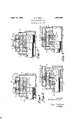
- a cylinder 5 providing a piston chamber with a main exhaust groove and port 6 intermediate its ends adapted to be overrun by a piston 7 reciprocating within the chamber. Movement of piston 7 is controlled by a spool valve 8 supported in a valve chest adjacent to, and in parallelism with, the piston chamber.
- the valve controls the distribution of motive fluid from inlet chamber 9 to the opposite ends of the piston chamber by opening or cutting off with its ends chambers 10 and 11 respectively.
- the valve is provided with spaced, radially-projecting flanges 12 and 13 which provide opposed pressure areas 14 and 15 which are of less extent than the end areas of the valve. Continuously open vent ports 16 and 17 communicate with areas 14 and 15 respectively. Cross passages 18 and 19 lead to areas 1 and 15 respectively from ports 20 and 21 in the 1829. Serial No. 353,927.
- piston chamber under control of piston head if communicate with the piston chamber byports 26 and 27 at either side of main exhaust 6 and provide auxiliary exhausts for the piston chamber.
- the span between auxiliary exhaust ports 26 and 27 is greater than the length of the controlling piston head 7.
- piston 7 As the piston moves rearwardly, it first closes main exhaust 6 whereupon the air in the rear end of the piston chamber continues to escape through auxiliary exhaust 26, passage 24, chamber 22, passage 23, and exhaust 6. Shortly thereafter piston 7 uncovers ports 20 and 27, the latter with its connecting passage 25 is sealed by flange 13 of the valve but motive fluid from the piston chambers enters port 20 and passes through passage 18 to be effective against area 14 in spite of the small vent 16. However, since the extent of area 14 is less than the opposed end area of the valve, the latter does not move. In its further movement, piston 7 closes auxiliary exhaust 2% whereupon the air trapped in the rearward end of the piston chamber and compressed by the piston develops pressure upon the rear loo end of the valve and shifts the latter to the forward position shown in Fig.
- valve 8 may have restricted ports therethrough, as indicated at a".
- Figs. 3 and 4 show an alternative design of the valve in which the smaller balancing valve faces or areas 14a and 15a are placed on opposite sides of a single, central, radial flange 12a and the auxiliary exhaust means on the valve consist of annular grooves or recesses 22a and 22?) which establish communication between auxiliary exhaust passages 24a and 28 when the valve is in its rearward position (Fig. 3) and between auxiliary exhaust passages 25a and 29 when the valve is in its forward position, respectively Fig. 4).
- the cycle of operation of the motor shown in Figs. 3 and 4 is the same as that shown in Figs. 1 and 2 and corresponding parts, ports, and passages are indicated by the same numerals as used in Figs. 1 and 2 with the addition of the letter a.
- piston controlled ports 21 and 24., as well as 20 and 27 of the form shown in Figs. 1 and 2, and ports 26a and 21a, as well as 2700 and 20a of the form shown in Figs. 3 and 4, are in line with one another transversely on the opposite sides of main exhaust 6 and 6a.
- the spread of auxiliary exhaust ports 26, 27 or 26a, 27a or at least the outer edges of the same shall be greater than the length of the piston head, so that both cannot be covered thereby simultaneously.
- leading to the small balancing areas of the valve may be greater, equal to, or less than the length of the piston head depending upon the desired timing of the throw of the valve.
- a fluid pressure tool comprising a cylinder providing a piston chamber having an exhaust port, a piston reciprocable in said chamber and arranged to overrun said port in both directions, a valve chest, a valve re.- ciprocable in said chest and controlling with its ends the distribution of motive fluid to said piston chamber, said valve having a central radial flange providing opposed areas less in extent than the end areas, continuously open vents of limited size for said smaller areas, cross ports under control of said piston extending from said piston chamber to said smaller areas, auxiliary exhaust means for said piston chamber under control of both said valve and said piston including grooves in the exterior of said valve on opposite sides of said flange and ports in said piston chamber on either side of said main. exhaust port, the span of said auxiliary exhaust ports being greater than the length of the control head of said piston and spaced from the ends of the piston chamber to cause the valve to be shifted by air trapped and compressed by the piston at the end of itsstroke.
Landscapes
- Physics & Mathematics (AREA)
- Fluid Mechanics (AREA)
- Engineering & Computer Science (AREA)
- Mechanical Engineering (AREA)
- Multiple-Way Valves (AREA)
Description
April 19, 1932.
ca. M. N-ELL FLUID PRESSURE TOOL Filed April 10, 1929 v wm INVENTOR. 0Jf0Ve M /1/e// ATTORNEY.
Patented Apr. 19, 1932 UNITED STATES PATENT OFFICE GUSTAVE M. NELL, F DETROIT, MICHIGAN, ASSIGNOR T0 CHICAGO PNEUMATIC TOOL 2 COMPANY, OF NEW YORK, N. Y., A CORPORATION OF NEW JERSEY FLUID PRESSURE TOOL Application filed April 10,
This invention relates to fluid pressure motors and tools and to the control and distribution of motive fluid in the same through the action of an automatically thrown valve which is arranged to move in timed relation with the reciprocations of the piston.
One object ofthe invention isto provide an improved valve and porting arrangement for a fluid pressure tool having a piston controlled exhaust. Another object is to make the valve positive in its movement and minimize or entirely avoid fluttering of the valve and of the piston. Other objects will be apparent from the detailed description which follows.
4 comprises a cylinder 5 providing a piston chamber with a main exhaust groove and port 6 intermediate its ends adapted to be overrun by a piston 7 reciprocating within the chamber. Movement of piston 7 is controlled by a spool valve 8 supported in a valve chest adjacent to, and in parallelism with, the piston chamber. The valve controls the distribution of motive fluid from inlet chamber 9 to the opposite ends of the piston chamber by opening or cutting off with its ends chambers 10 and 11 respectively. In addition to the opposed pressure areas formed by the ends of the valve, the valve is provided with spaced, radially-projecting flanges 12 and 13 which provide opposed pressure areas 14 and 15 which are of less extent than the end areas of the valve. Continuously open vent ports 16 and 17 communicate with areas 14 and 15 respectively. Cross passages 18 and 19 lead to areas 1 and 15 respectively from ports 20 and 21 in the 1829. Serial No. 353,927.
piston chamber under control of piston head if communicate with the piston chamber byports 26 and 27 at either side of main exhaust 6 and provide auxiliary exhausts for the piston chamber. I The span between auxiliary exhaust ports 26 and 27 is greater than the length of the controlling piston head 7.
The operation of the motor is as follows: With the parts in the position shown in Fig. 1., live motive fluid from inlet 9 moves past the forward end of the valve into a chamber 111. and thence into the forward end of the piston chamber driving piston 7 rearwardly, the rear end of the valve shutting off communication between inlet 9 and chamber 10. The rear end of the piston chamber is open to exhaust both through the main exhaust 6 and auxiliary port 26. Accordingly, low or substantially atmospheric pressure obtains upon the opposed areas 14:, 15, and the rear end of the valve, the valve being held in its position by the pressure of the entering motive fluid on the forward end of the valve. As the piston moves rearwardly, it first closes main exhaust 6 whereupon the air in the rear end of the piston chamber continues to escape through auxiliary exhaust 26, passage 24, chamber 22, passage 23, and exhaust 6. Shortly thereafter piston 7 uncovers ports 20 and 27, the latter with its connecting passage 25 is sealed by flange 13 of the valve but motive fluid from the piston chambers enters port 20 and passes through passage 18 to be effective against area 14 in spite of the small vent 16. However, since the extent of area 14 is less than the opposed end area of the valve, the latter does not move. In its further movement, piston 7 closes auxiliary exhaust 2% whereupon the air trapped in the rearward end of the piston chamber and compressed by the piston develops pressure upon the rear loo end of the valve and shifts the latter to the forward position shown in Fig. 2, ust before, or at about the time when, piston 7 overruns main exhaust 6, thereby venting the forward end of the pistgn chamber. Motive fluid from inlet 9 then passes the rear end of the valve through chamber 10 into the rear end of the piston chamber driving the piston forwardly. As piston 7 on its forward movement closes main exhaust 6, the pressure ahead of the piston continues to escape through auxiliary exhaust port 27, passage 25, valve chamber 22, passage 23', and main exhaust 6. Shortly thereafter port 21 is uncovered admitting motive fluid from the rear end of the piston chamber through passage 19 against valve area 15 but by reason of the smallness of the same the valve does not move but is partially placed in balance. On closing auxiliary exhaust port 27, the piston compresses the air trapped in the forward end. of the piston chamber and this pressure on the forward end of the valve, plus the pressure already on area 15, throws the valve to the position shown in Fig. 1 at about the time that the piston strikes its blow and opens main exhaust port 6, thus completing the cycle. If necessary or desirable to provide a greater quantity of fluid to be trapped and compressed, valve 8 may have restricted ports therethrough, as indicated at a".
Figs. 3 and 4 show an alternative design of the valve in which the smaller balancing valve faces or areas 14a and 15a are placed on opposite sides of a single, central, radial flange 12a and the auxiliary exhaust means on the valve consist of annular grooves or recesses 22a and 22?) which establish communication between auxiliary exhaust passages 24a and 28 when the valve is in its rearward position (Fig. 3) and between auxiliary exhaust passages 25a and 29 when the valve is in its forward position, respectively Fig. 4). The cycle of operation of the motor shown in Figs. 3 and 4 is the same as that shown in Figs. 1 and 2 and corresponding parts, ports, and passages are indicated by the same numerals as used in Figs. 1 and 2 with the addition of the letter a.
It is to be noted that piston controlled ports 21 and 24., as well as 20 and 27 of the form shown in Figs. 1 and 2, and ports 26a and 21a, as well as 2700 and 20a of the form shown in Figs. 3 and 4, are in line with one another transversely on the opposite sides of main exhaust 6 and 6a. For the purpose of preventing a tendency to dead centering or fluttering of either the piston or the valve, or both, it is one of the important features of this invention that the spread of auxiliary exhaust ports 26, 27 or 26a, 27a or at least the outer edges of the same shall be greater than the length of the piston head, so that both cannot be covered thereby simultaneously. The spread of the ports 20, 21 or 20a, 21a
leading to the small balancing areas of the valve, may be greater, equal to, or less than the length of the piston head depending upon the desired timing of the throw of the valve.
While the invention has been herein disclosed in what are now considered to be pre ferred forms, it is to be understood that the invention is not limited to the specific details thereof but covers all changes, modifications, and adaptations within the scope of the appended claim.
I claim as my invention:
A fluid pressure tool comprising a cylinder providing a piston chamber having an exhaust port, a piston reciprocable in said chamber and arranged to overrun said port in both directions, a valve chest, a valve re.- ciprocable in said chest and controlling with its ends the distribution of motive fluid to said piston chamber, said valve having a central radial flange providing opposed areas less in extent than the end areas, continuously open vents of limited size for said smaller areas, cross ports under control of said piston extending from said piston chamber to said smaller areas, auxiliary exhaust means for said piston chamber under control of both said valve and said piston including grooves in the exterior of said valve on opposite sides of said flange and ports in said piston chamber on either side of said main. exhaust port, the span of said auxiliary exhaust ports being greater than the length of the control head of said piston and spaced from the ends of the piston chamber to cause the valve to be shifted by air trapped and compressed by the piston at the end of itsstroke.
Signed by me at Detroit, in the county of Wayne and State of Michigan, this 4 day of April, 1929.
GUSTAVE. M NELL.
Priority Applications (1)
| Application Number | Priority Date | Filing Date | Title |
|---|---|---|---|
| US353927A US1854856A (en) | 1929-04-10 | 1929-04-10 | Fluid pressure tool |
Applications Claiming Priority (1)
| Application Number | Priority Date | Filing Date | Title |
|---|---|---|---|
| US353927A US1854856A (en) | 1929-04-10 | 1929-04-10 | Fluid pressure tool |
Publications (1)
| Publication Number | Publication Date |
|---|---|
| US1854856A true US1854856A (en) | 1932-04-19 |
Family
ID=23391178
Family Applications (1)
| Application Number | Title | Priority Date | Filing Date |
|---|---|---|---|
| US353927A Expired - Lifetime US1854856A (en) | 1929-04-10 | 1929-04-10 | Fluid pressure tool |
Country Status (1)
| Country | Link |
|---|---|
| US (1) | US1854856A (en) |
-
1929
- 1929-04-10 US US353927A patent/US1854856A/en not_active Expired - Lifetime
Similar Documents
| Publication | Publication Date | Title |
|---|---|---|
| US1854856A (en) | Fluid pressure tool | |
| US1690126A (en) | Reciprocating engine | |
| US1832432A (en) | Pneumatic hammer | |
| US1986084A (en) | Controlling means for double-acting reciprocating engines without flywheel | |
| US2003121A (en) | Percussive tool valve | |
| US2398992A (en) | Pneumatic tool | |
| US1913916A (en) | Controlling apparatus for pneumatic tools and the like | |
| US1711811A (en) | Valve for rock drills | |
| US1871726A (en) | Fluid pressure tool | |
| US1969539A (en) | Pneumatic and like tool | |
| US2307866A (en) | Rock drill | |
| US1637001A (en) | Fluid-operated tool | |
| US2448875A (en) | Valve for rock drills | |
| US1760277A (en) | Fluid-pressure tool | |
| US1660528A (en) | Rock drill | |
| US806128A (en) | Rock-boring machine. | |
| US1589295A (en) | Reciprocatory hammer tool | |
| US1348280A (en) | Rock-drill or impact engine | |
| US1078188A (en) | Percussive tool. | |
| US1615890A (en) | Pneumatic hammer | |
| US1920763A (en) | Valve controlled fluid pressure tool | |
| US932124A (en) | Mining-machine. | |
| US1898494A (en) | Fluid pressure tool | |
| US1352191A (en) | Pneumatic tool | |
| US589354A (en) | Fluid-pressure engine |