US1854855A - Pipe joint - Google Patents
Pipe joint Download PDFInfo
- Publication number
- US1854855A US1854855A US517615A US51761531A US1854855A US 1854855 A US1854855 A US 1854855A US 517615 A US517615 A US 517615A US 51761531 A US51761531 A US 51761531A US 1854855 A US1854855 A US 1854855A
- Authority
- US
- United States
- Prior art keywords
- pipes
- packing ring
- pipe joint
- coupled
- seam
- Prior art date
- Legal status (The legal status is an assumption and is not a legal conclusion. Google has not performed a legal analysis and makes no representation as to the accuracy of the status listed.)
- Expired - Lifetime
Links
- 238000012856 packing Methods 0.000 description 16
- 239000012530 fluid Substances 0.000 description 4
- 238000010276 construction Methods 0.000 description 2
- 239000000428 dust Substances 0.000 description 2
- 238000005192 partition Methods 0.000 description 2
Images
Classifications
-
- F—MECHANICAL ENGINEERING; LIGHTING; HEATING; WEAPONS; BLASTING
- F16—ENGINEERING ELEMENTS AND UNITS; GENERAL MEASURES FOR PRODUCING AND MAINTAINING EFFECTIVE FUNCTIONING OF MACHINES OR INSTALLATIONS; THERMAL INSULATION IN GENERAL
- F16L—PIPES; JOINTS OR FITTINGS FOR PIPES; SUPPORTS FOR PIPES, CABLES OR PROTECTIVE TUBING; MEANS FOR THERMAL INSULATION IN GENERAL
- F16L17/00—Joints with packing adapted to sealing by fluid pressure
- F16L17/02—Joints with packing adapted to sealing by fluid pressure with sealing rings arranged between outer surface of pipe and inner surface of sleeve or socket
- F16L17/04—Joints with packing adapted to sealing by fluid pressure with sealing rings arranged between outer surface of pipe and inner surface of sleeve or socket with longitudinally split or divided sleeve
Definitions
- This invention relates to improvements in pipe joints of the kind wherein a tight joint between an elastic packing ring applied to the seam between coupled pipes to embrace the parts and the body of the pipes is insured by the pressure of fluid in the pipes, and has for its object to provide an improved pipe joint of the kind above referred to.
- the application is less easy and the elastic packing ring is liable to be more or less damaged upon inserting therein the pipes to be coupled, or relative movement between the packing ring and the pipes, so that its tight fit with thepipes is not insured, and dust or other foreign matter may deposit on its inner side, the inner side being directly exposed to fluid in the pipes.
- the elastic packing ring is made in a tube form and its inner side communicates with fluid in the pipes through an opening, so that the application is easy and dust or other foreign matterv will not deposit on inner side of the elastic packing ring.
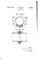
- Fig. 1 is a side view, partly in section, the pipe joint embodying the invention.
- Fig. 2 is a vertical section thereof.
- pipes to be coupled 1 and 2 are abutted end to end.
- 3 is an opening formed at jointing seam of the pipes, one half of which is formed at the end of the pipe 1 and other half at the end of the pipe 2.
- An elastic packing ring 4 substantially of a tube form with two bores is put on the seam of the pipes to extend to both sides of said seamthrough a suitable distance to embrace the parts.
- Ehe packing ring is provided with 5 for making a communication between its bores and the inner side of the pipes through the opening 3.
- the elastic packing ring is tightly grasped by means of a clamp 6 which may be of twO or more sections adapted to be secured by means of bolts 7 and nut 8 as shown.
- a pipe joint comprising an elastic packing ring substantially of a tube form with an opening and adapted to embrace over a seam I of coupled pipes abutted end to end and a clamp for grasping the packing ring, said opening being adapted to communicate with another opening formed at the seam of the coupled pipes and consequently with inside as shown and described.
- a pipe joint comprising an elastic packing ring having substantially the form of a double tube with a central longitudinal partition therein, means defining an opening for the said tube common to the two portions divided by the partition, the said packing ring embracing the seam of coupled pipes abutting end to end, and a clamp fitting about and grasping the packing ring, an opening being formed at the seam of the coupled pipes and consequently with the interior of the pipes, whereby the pressure occasioned by the fluid flowing through the pipes will flow through the said tubular portions and will insure a tight seal.
Landscapes
- Engineering & Computer Science (AREA)
- General Engineering & Computer Science (AREA)
- Physics & Mathematics (AREA)
- Fluid Mechanics (AREA)
- Mechanical Engineering (AREA)
- Joints With Sleeves (AREA)
Description
April 19, 1932.
k. NAKASHIMA PIPE JOINT Filed Feb. 21, 1951 A TTORNE Y.
an opening Patented Apr. 1 9, 1932 PATENT OFFICE KISABURO NAKASHIMA, OF KOISHIKAWA-KU, TOKYO-SKI, JAPAN PIPE JOINT Application filed February 21, 1931, Serial No. 517,615, and in Japan March 30, 1930.
This invention relates to improvements in pipe joints of the kind wherein a tight joint between an elastic packing ring applied to the seam between coupled pipes to embrace the parts and the body of the pipes is insured by the pressure of fluid in the pipes, and has for its object to provide an improved pipe joint of the kind above referred to.
In some well known constructions of the pipe oint of the said kind, the application is less easy and the elastic packing ring is liable to be more or less damaged upon inserting therein the pipes to be coupled, or relative movement between the packing ring and the pipes, so that its tight fit with thepipes is not insured, and dust or other foreign matter may deposit on its inner side, the inner side being directly exposed to fluid in the pipes.
In the pipe joint according to the invention, the elastic packing ring is made in a tube form and its inner side communicates with fluid in the pipes through an opening, so that the application is easy and dust or other foreign matterv will not deposit on inner side of the elastic packing ring.
In the accompanying drawings;
Fig. 1 is a side view, partly in section, the pipe joint embodying the invention.
Fig. 2 is a vertical section thereof.
Referring to the drawings, pipes to be coupled 1 and 2 are abutted end to end. 3 is an opening formed at jointing seam of the pipes, one half of which is formed at the end of the pipe 1 and other half at the end of the pipe 2. An elastic packing ring 4 substantially of a tube form with two bores is put on the seam of the pipes to extend to both sides of said seamthrough a suitable distance to embrace the parts. Ehe packing ring is provided with 5 for making a communication between its bores and the inner side of the pipes through the opening 3. j
The elastic packing ring is tightly grasped by means of a clamp 6 which may be of twO or more sections adapted to be secured by means of bolts 7 and nut 8 as shown.
With this construction, pressure in the tubes will be transmitted to air in inside of the packing ring through openin s 3 and 5, whereby the packing ring ten s to be expanded and is tightly pressed against the outer walls adjacent the seam of the coupled pipes to insure a tight joint between the-packing ring and the body of the coupled ipes.
Having now particularly describes and ascertained the nature of my said invention and in what manner the same is to be performed, I claim:
1, A pipe joint comprising an elastic packing ring substantially of a tube form with an opening and adapted to embrace over a seam I of coupled pipes abutted end to end and a clamp for grasping the packing ring, said opening being adapted to communicate with another opening formed at the seam of the coupled pipes and consequently with inside as shown and described.
of the pipes,
2. A pipe joint comprising an elastic packing ring having substantially the form of a double tube with a central longitudinal partition therein, means defining an opening for the said tube common to the two portions divided by the partition, the said packing ring embracing the seam of coupled pipes abutting end to end, and a clamp fitting about and grasping the packing ring, an opening being formed at the seam of the coupled pipes and consequently with the interior of the pipes, whereby the pressure occasioned by the fluid flowing through the pipes will flow through the said tubular portions and will insure a tight seal.
In testimony whereof I aflix my signature.
KISABURO NAKASHIMA.
Applications Claiming Priority (1)
| Application Number | Priority Date | Filing Date | Title |
|---|---|---|---|
| JP1854855X | 1930-03-30 |
Publications (1)
| Publication Number | Publication Date |
|---|---|
| US1854855A true US1854855A (en) | 1932-04-19 |
Family
ID=16171584
Family Applications (1)
| Application Number | Title | Priority Date | Filing Date |
|---|---|---|---|
| US517615A Expired - Lifetime US1854855A (en) | 1930-03-30 | 1931-02-21 | Pipe joint |
Country Status (1)
| Country | Link |
|---|---|
| US (1) | US1854855A (en) |
Cited By (11)
| Publication number | Priority date | Publication date | Assignee | Title |
|---|---|---|---|---|
| US2424810A (en) * | 1944-08-11 | 1947-07-29 | Serew Conveyor Corp | Housing and conveyor connections for screw conveyors |
| US2513363A (en) * | 1945-10-25 | 1950-07-04 | Robert A Richter | Oil cooler |
| US2753074A (en) * | 1950-03-06 | 1956-07-03 | Interpa Corp Registered Trust | Container seals or closures |
| US3038732A (en) * | 1958-04-07 | 1962-06-12 | Texas Pipe Line Company | Inflatable seal bushing for pipeline casing |
| US3589753A (en) * | 1968-08-05 | 1971-06-29 | Quartz And Silice | Coupling apparatus |
| FR2399604A1 (en) * | 1977-08-05 | 1979-03-02 | Durapipe Ltd | Pipes clamp on coupling arrangement - uses end flanged tubular parts, and clamping ring with groove having sloping side wall for forming wedging action between flanges |
| US4163571A (en) * | 1977-07-18 | 1979-08-07 | Durapipe Limited | Pipe couplings |
| US4344720A (en) * | 1979-07-04 | 1982-08-17 | Piesold David D A | Decants of tailings dams |
| US20040154142A1 (en) * | 2003-02-12 | 2004-08-12 | David Capra | Sight gauge hose clamp |
| US20110079018A1 (en) * | 2009-10-01 | 2011-04-07 | Tania Pucovsky | Bleed air transfer tube |
| US10975992B1 (en) | 2017-07-01 | 2021-04-13 | Principle CNC Mfg, Inc. | Liquid manure hose coupler |
-
1931
- 1931-02-21 US US517615A patent/US1854855A/en not_active Expired - Lifetime
Cited By (12)
| Publication number | Priority date | Publication date | Assignee | Title |
|---|---|---|---|---|
| US2424810A (en) * | 1944-08-11 | 1947-07-29 | Serew Conveyor Corp | Housing and conveyor connections for screw conveyors |
| US2513363A (en) * | 1945-10-25 | 1950-07-04 | Robert A Richter | Oil cooler |
| US2753074A (en) * | 1950-03-06 | 1956-07-03 | Interpa Corp Registered Trust | Container seals or closures |
| US3038732A (en) * | 1958-04-07 | 1962-06-12 | Texas Pipe Line Company | Inflatable seal bushing for pipeline casing |
| US3589753A (en) * | 1968-08-05 | 1971-06-29 | Quartz And Silice | Coupling apparatus |
| US4163571A (en) * | 1977-07-18 | 1979-08-07 | Durapipe Limited | Pipe couplings |
| FR2399604A1 (en) * | 1977-08-05 | 1979-03-02 | Durapipe Ltd | Pipes clamp on coupling arrangement - uses end flanged tubular parts, and clamping ring with groove having sloping side wall for forming wedging action between flanges |
| US4344720A (en) * | 1979-07-04 | 1982-08-17 | Piesold David D A | Decants of tailings dams |
| US20040154142A1 (en) * | 2003-02-12 | 2004-08-12 | David Capra | Sight gauge hose clamp |
| US20110079018A1 (en) * | 2009-10-01 | 2011-04-07 | Tania Pucovsky | Bleed air transfer tube |
| US8490409B2 (en) | 2009-10-01 | 2013-07-23 | Pratt & Whitney Canada Corp. | Bleed air transfer tube |
| US10975992B1 (en) | 2017-07-01 | 2021-04-13 | Principle CNC Mfg, Inc. | Liquid manure hose coupler |
Similar Documents
| Publication | Publication Date | Title |
|---|---|---|
| US1854855A (en) | Pipe joint | |
| US1876455A (en) | inshaw | |
| US1571343A (en) | Pipe union | |
| FR2349782A1 (en) | Pipe couplings with axially compressed annular polyurethane seals - for butt joint seals which can tolerate vibration | |
| US1302022A (en) | Expansion-joint. | |
| US3499666A (en) | Seal arrangement for lined tubular members | |
| US963248A (en) | Pipe-fitting. | |
| US365425A (en) | Pipe-joint | |
| US1993372A (en) | Screwed pipe joint and in fittings relating thereto | |
| US1512219A (en) | Condenser joint | |
| US1720912A (en) | Heat interchanger | |
| US2828979A (en) | Flanged pipes coupled by resilient sealing gasket having venturi-like fluid passage | |
| US3404906A (en) | Expansion joint | |
| US1779902A (en) | Expansible pipe joint | |
| US123954A (en) | Improvement in pipe-joints | |
| SU64440A1 (en) | Pipe seal | |
| US1339739A (en) | Boiler-tube end section | |
| US927659A (en) | Flexible metallic pipe-coupling. | |
| US870200A (en) | Angle-pipe coupling. | |
| US1847837A (en) | Method of connecting pipes | |
| US1837490A (en) | Expansible joint for pipe lines | |
| USD1108589S1 (en) | Sealing sleeve for pipe connection | |
| US378150A (en) | Pipe-coupling | |
| CN206513962U (en) | A kind of high sensitivity bellows | |
| US1664941A (en) | Pipe joint |