US1854854A - Amplifier system - Google Patents
Amplifier system Download PDFInfo
- Publication number
- US1854854A US1854854A US337147A US33714729A US1854854A US 1854854 A US1854854 A US 1854854A US 337147 A US337147 A US 337147A US 33714729 A US33714729 A US 33714729A US 1854854 A US1854854 A US 1854854A
- Authority
- US
- United States
- Prior art keywords
- filament
- grid
- tube
- circuit
- plate
- Prior art date
- Legal status (The legal status is an assumption and is not a legal conclusion. Google has not performed a legal analysis and makes no representation as to the accuracy of the status listed.)
- Expired - Lifetime
Links
- 230000008878 coupling Effects 0.000 description 9
- 238000010168 coupling process Methods 0.000 description 9
- 238000005859 coupling reaction Methods 0.000 description 9
- 238000004804 winding Methods 0.000 description 6
- 230000001276 controlling effect Effects 0.000 description 2
- 238000010438 heat treatment Methods 0.000 description 2
- 230000003472 neutralizing effect Effects 0.000 description 1
- 230000001105 regulatory effect Effects 0.000 description 1
- 239000013589 supplement Substances 0.000 description 1
Images
Classifications
-
- H—ELECTRICITY
- H04—ELECTRIC COMMUNICATION TECHNIQUE
- H04B—TRANSMISSION
- H04B15/00—Suppression or limitation of noise or interference
- H04B15/005—Reducing noise, e.g. humm, from the supply
Definitions
- an amplifier system including two three-electrode vacuum tubes VT1 and VT2 connected in cascade relation for amplifying audio frequency currents supplied to the system'through an input device, such as a transformer T1.
- a source of potential S having positive and negative terminals as indicated for energizing the plate and grid electrodes of i the tubes, which source may be any source of unidirectional current, such as the unidirectional pulsating output from an lalternating current rectifier followed .byv a suitable filter system in accordance with general practice.
- the filaments of the tubes are indicated as supplied with raw alternating current for heating through transformers T3 and T2, though a single transformer may be used for the filaments of several tubes, or any other )E suitable source of current supply and system for filament heating may be employed.
- I show the filament of tube VT1 connected to the negative terminal of source S by way of a center-tap potentiometer P1 and the primary winding of transformer T2, Aand therefore in series with the plate circuit, so that the connection of the grid of this tube to the negative side of the primary winding of T2 permits of employingr the difference of potential developed therein as a grid biasing potential.
- the winding of the primary of the transformer may be chosen to give such d1- rect current resistance that the normal direct current component of plate current employed in tube VT1 results in developing the desired grid biasing potential for the tube.
- transformer T2 does not interfere with the signal current variations flowing through the primary Winding, and thus exciting the secondary winding for transfer of signal current energy to the succeeding tube VT2.
- the condenser C1 of low impedance-to signal currents and high resistance Rl form a filter system for by-passing grid circuits signal currents directly to the filament and reducing and regulating signal current coupling between plate and grid circuits.
- association witlrtube VT2 I show a choke and condenser form of output couplingfor a loud speaker or other sound reproducer LS, the choke and condenser comlination comprising the coil L and condenser 3. tion between the filament of tube VT2, shunted by a center-tap potentiometer P2, and the negative terminal of source S,*thus employing as before the difference of potential developed therein for energizing the grid of tube VT2 ⁇ .
- I may supplement the direct current resistance of the choke coil by a resistance R3 in order .to develop therequired biasing potential, which may be desirable in case the tube VT2 is a so-called power amplifier requiring potential for biasing too large to be satisfactorily developed in coil Ii.'
- the arrangement maybe the same for tube VT2 as shown for tube VTl.
- a filter system comprising condenser C2 and resistance R2 is shownV for the same purpose as outlined in connection with tube VTl.
- An amplifier system having a plurality of amplifier tubes, each of said tubes having grid-filament and plate-filament circuits, each of said plate-filament circuits having a source of power and an inductance of known resistance between said source of power and said filament, said grid-filament circuits also including said inductance, whereby the average potentials of said grids are maintained at known values relative to those of said filaments, at least one of said inductances constituting the primary of a transformer, the secondary of which is included in the gridfilament circuit of a succeeding tube whereby energy is transferred between the tubes.
- An amplifier system including an amplifier tube having grid-filament and plate-filament circuits, said plateefilament circuit including a source of power and aA reactive impedance between said source and said filament, the grid-filament Vcircuit of said tube including said reactive impedance whereby the average potential of said grid is maintained at a known value relative to that of said filament, said impedance constituting the primary of an output transformer for the plate-filament circuit of said tube.
- An amplier system including a plurality of amplifier tubes in cascade, each tubehaving grid-filament and plate-filament circuits, each of said plate-filament circuits including a source of power, inductances and resistances between said source of power and said filaments, said grid-filament circuits also includingsaid inductances and resistances, and filter resistances and condensers also included in said grid-filament circuit whereby the average potentials of said grids are maintained at known potentials relative to said filaments.
- An amplifier system including a plurality of amplifier tubes in cascade, each tube having grid-filament and plate-filament circuits at least one of said plate-filament circuits including an inductance of known resistance, the grid-filament circuit of said tube also including said induetanee and an indicator and condenser series connected between the plate of said tube and the filament terminal of one of said inductances, whereby said induetance both shunts signal Acurrent through said indicator and maintains the average potential of said grid at a known value relative to that of said filament.
- An amplifier system including a plurality of amplifier tubes in cascade, each tube having grid-filament and plate-filament circuits, at least one of said plate-filament circuits including a source of power, a reactive impedance and a variable resistance between said source of power and said filament, the grid-filament circuit of said tube also including said impedance and resistance, and an indicator and condenser series connected between the plate of said tube and a point between the said impedance and resistance and the said filament whereby said inductance both shunts signal current through said indicator and maintains the average potential of said grid at a known value relative to that of said filament.
- An amplifier system including a plurality of amplifier tubes in cascade, each tube having grid-filament and plate-filament circuits, each of said plate-filament circuits including a source of power and reactive impedances between said source of power and said filaments, the grid-filament circuits of each of said tubes also including said impedances whereby the average potentials of said grids are maintained at known values relative to those of said filaments, at least one of said impedances constituting the primary of a transformer, the secondary of which is included in the grid-filament circuit of a succeeding tube, whereby energy is transferred between tubes and the plate-filament circuit of at least one of said tubes having an indicator and condenser series connected between the plate of said tube and a point between the impedance and the filament in its respective plate-filament circuit.
- An amplifier system having a plurality of amplifier tubes, each of said tubes having grid-filament and plate-filament circuits, each of said plate-filament circuits having a source of power andan inductance of known resistance between said source of power and said filament, said grid-filament circuits also including said inductances, whereby the average potential of said grids are maintained at known values relative to that tube also including said induetance, means for shunting the signal energy in said grid-lilainent circuit around said inductance, and an indicator and a condenser series connected between the plate of said tube and the filament terminal of one of said inductances, whereby said inductance both shunts signal current through said indicator and 1naintains the average potential of said grid at a known value relative to that of said iilament.
- An ampliier system including a plurality of ampliner tubes in cascade each oi' said tubes having grid-iilament and plateiilament circuits, at least one oit said plateilament circuits including a source ci power and an inductance and a variable resistance between said source of power and said fila'- inent, the grid-filament circuit ci said tube also including said inductance and resistance, means for shunting the signal energy in said grid-iilainent circuit around said impedance, and an indicator and condenser series connected between the plate of said tube and a point between said inductance and resistance and the said lilament wherebli,7 said inductance both shunts signal current through said indicator and maintains the average potential of said grid at a known value, relative to that of said filament.
- An ampliier system including a plurality of amplifier tubes in cascade, cach tube having grid-filament and plate-iilament circuits, each of said plate-filament circuits including a source of power and an inductance between said source of power and said filam nts, the grid-filament circuit of each of said tubes also including one of said inductances, whereby the average potentials ot.' aid grids are maintained at known values relative to those of said filaments, at leait one of said inductances constituting the primary of a transformer, they secondary ot which is included in the grid-filament ci 1cuit of a succeeding tube, whereby energy is trans Jferred between the tubes, means for shunting the signal energy in said grid-filament circuit around said inductance, and thc plateilanient circuit of at least one oi said tubes having an indicator and a condenser series connected between the plate of said tube and the point between the inductance and the lilament in
- An amplifier system including a plurality of amplifier tubes in cascade, each tube having grid-fila1nent and plate-filament circuits, each of said plate-filament circuits including a source of power and an inductance between said source of power and said iilaments, the grid-iilainent circuit of each ot said tubes alsoincluding one oi said inductances, whereby the average potentials of said grids are maintained at known values relative to those of said filaments, at one ci said inductances constituting the primary of a transformer, the secondary of input circuit tor coupling said first named Youtput circuit to the input circuit of said input circuit and anoutput circuitior said and the filament in its respective plate lila-T ment circuit, and means for shunting the signal energy in the grid-lilament circuit of said last mentioned tube around the inductance in said grid-iilament circuit.
- a space discharge device comprising a cathode, a grid 'electrode and an anode so inter-related as to torni an input circuit and an output circuit for said device, a second space discharge dcvice having an input circuit and an output circuit, means included iii said nrst named second mentioned space discharge device, said means being adapted to maintain the average potential of said grid electrode at known potential relative to said cathode.
- ll. ln an ampliiier system, a space discharge device having aV cathode, a grid electrode and an anode related so as to form an input circuit and an output circuit, a second space discharge device having au input circuit and an output circuit, coupling means comprising a transformer having its primary included in both said first named input and output circuits and its secondary in the input circuit of said second named space discharge device, said transformer being adapted to couple said first named output circuit to the input of said second spaced discharge device, said primary beine ⁇ adapted to maintain the average potential of said grid electrode at L5 known potential relative to said cathode.
- a space discharge device having a cathode, a grid electrode and an anode related so as to form an device
- a second space discharge device having an input circuit and an output circuit
- a coupling means comprising a transformer having its primary included in both said irst named input and output circuits and its secondary in the input circuit of said second named space discharge device, said transformer being adapted to couple said first named output circuit to the input of said second space discharge device, a condenser connected between said cathode and said grid electrode, a resistance connected between the grid terminal of said condenser and one end of said primary, said primary being adapted to maintain the average potential of said grid electrode at known potential relative to said cathode.
- a space discharge device comprising a cathode, an auX- iliary electrode and an anode so inter-related as to form an input circuit and an output circuit for said device, an energy utilizing means having an input circuit, means included in said iirst-named input circuit for coupling said output circuit to the input circuit of said utilizing means, said coupling .means being adapted to maintain said auX- iliary electrode at a known average potential relative to said cathode.
- a space discharge device comprising a cathode, a grid electrode and an anode so inter-related as to .form an input circuit and an output circuit for said device, a source of uni-directional pulsating current connected in said output circuit, an energy utilizing means having an input circuit, means included in said iirstnamed input circuit for coupling said output circuit to the input circuit of said utiliziing means, and means Jfor impressing the potential developed in said coupling means, from the iiow of current therein from said source, upon the grid electrode of said device and means for controlling the degree of the fluctuating component of said grid impressed potential.
Landscapes
- Engineering & Computer Science (AREA)
- Computer Networks & Wireless Communication (AREA)
- Signal Processing (AREA)
- Amplifiers (AREA)
Description
April 19, 1932. B. F. MlEssNER AMPLIFIER SYSTEM Filed Feb. 2, 1929 Patented Apr. 19, 1932 UNITED STATES IM'IEN'r OFFICE BENJAMIN F. MIESSNER,'OF SHORT HILLS, NEW JERSEY, ASSIGNOR, BY MESNE AS- SIGNMENTS, TO RADIO CORPORATION OF AMERICA, OF NEW YORK, N. Y., A CORPO- RATION OF DELAW'ABE AMPLIFIER SYSTEM Application filed February 2,V 1929. Serial No. 337,147.
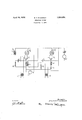
* reference to the one figure of the accompanying drawings in which isV shown an amplifier system including two three-electrode vacuum tubes VT1 and VT2 connected in cascade relation for amplifying audio frequency currents supplied to the system'through an input device, such as a transformer T1. There is shown a source of potential S, having positive and negative terminals as indicated for energizing the plate and grid electrodes of i the tubes, which source may be any source of unidirectional current, such as the unidirectional pulsating output from an lalternating current rectifier followed .byv a suitable filter system in accordance with general practice.
The filaments of the tubes are indicated as supplied with raw alternating current for heating through transformers T3 and T2, though a single transformer may be used for the filaments of several tubes, or any other )E suitable source of current supply and system for filament heating may be employed. Y
I show the filament of tube VT1 connected to the negative terminal of source S by way of a center-tap potentiometer P1 and the primary winding of transformer T2, Aand therefore in series with the plate circuit, so that the connection of the grid of this tube to the negative side of the primary winding of T2 permits of employingr the difference of potential developed therein as a grid biasing potential. The winding of the primary of the transformer may be chosen to give such d1- rect current resistance that the normal direct current component of plate current employed in tube VT1 results in developing the desired grid biasing potential for the tube.
It is seen that this connection of transformer T2 does not interfere with the signal current variations flowing through the primary Winding, and thus exciting the secondary winding for transfer of signal current energy to the succeeding tube VT2.
The condenser C1 of low impedance-to signal currents and high resistance Rl form a filter system for by-passing grid circuits signal currents directly to the filament and reducing and regulating signal current coupling between plate and grid circuits.
In association witlrtube VT2 I show a choke and condenser form of output couplingfor a loud speaker or other sound reproducer LS, the choke and condenser comlination comprising the coil L and condenser 3. tion between the filament of tube VT2, shunted by a center-tap potentiometer P2, and the negative terminal of source S,*thus employing as before the difference of potential developed therein for energizing the grid of tube VT2`. If needed I may supplement the direct current resistance of the choke coil by a resistance R3 in order .to develop therequired biasing potential, which may be desirable in case the tube VT2 is a so-called power amplifier requiring potential for biasing too large to be satisfactorily developed in coil Ii.'
If a two-winding output transformer is used for connecting the translating device LS to the system in lieu of the choke and condenser coupling, the arrangement maybe the same for tube VT2 as shown for tube VTl. A filter system comprising condenser C2 and resistance R2 is shownV for the same purpose as outlined in connection with tube VTl.
It is seen that bythe connections I employ it is possible to dispense with the usual grid Vbiasing batteries or biasing resistors employed I insert the choke coil L in the connec-V these elements. The fluctuating or alternating current component passing through inductance L and resistance R3 introduces fluctuating potentials on the grid out of phase with those on the plate, so that selecting the values of resistance R2 and condenser C2 to control the degree of these fluctuating grid potentials permits of neutralizing wholly or in part as desired the residual fluctuations through translating device LS.
Having thus described my invention, what I claim is:
1. An amplifier system having a plurality of amplifier tubes, each of said tubes having grid-filament and plate-filament circuits, each of said plate-filament circuits having a source of power and an inductance of known resistance between said source of power and said filament, said grid-filament circuits also including said inductance, whereby the average potentials of said grids are maintained at known values relative to those of said filaments, at least one of said inductances constituting the primary of a transformer, the secondary of which is included in the gridfilament circuit of a succeeding tube whereby energy is transferred between the tubes.
2. An amplifier system including an amplifier tube having grid-filament and plate-filament circuits, said plateefilament circuit including a source of power and aA reactive impedance between said source and said filament, the grid-filament Vcircuit of said tube including said reactive impedance whereby the average potential of said grid is maintained at a known value relative to that of said filament, said impedance constituting the primary of an output transformer for the plate-filament circuit of said tube.
3. An amplier system including a plurality of amplifier tubes in cascade, each tubehaving grid-filament and plate-filament circuits, each of said plate-filament circuits including a source of power, inductances and resistances between said source of power and said filaments, said grid-filament circuits also includingsaid inductances and resistances, and filter resistances and condensers also included in said grid-filament circuit whereby the average potentials of said grids are maintained at known potentials relative to said filaments. l
4. An amplifier system including a plurality of amplifier tubes in cascade, each tube having grid-filament and plate-filament circuits at least one of said plate-filament circuits including an inductance of known resistance, the grid-filament circuit of said tube also including said induetanee and an indicator and condenser series connected between the plate of said tube and the filament terminal of one of said inductances, whereby said induetance both shunts signal Acurrent through said indicator and maintains the average potential of said grid at a known value relative to that of said filament.
5. An amplifier system including a plurality of amplifier tubes in cascade, each tube having grid-filament and plate-filament circuits, at least one of said plate-filament circuits including a source of power, a reactive impedance and a variable resistance between said source of power and said filament, the grid-filament circuit of said tube also including said impedance and resistance, and an indicator and condenser series connected between the plate of said tube and a point between the said impedance and resistance and the said filament whereby said inductance both shunts signal current through said indicator and maintains the average potential of said grid at a known value relative to that of said filament.
6. An amplifier system including a plurality of amplifier tubes in cascade, each tube having grid-filament and plate-filament circuits, each of said plate-filament circuits including a source of power and reactive impedances between said source of power and said filaments, the grid-filament circuits of each of said tubes also including said impedances whereby the average potentials of said grids are maintained at known values relative to those of said filaments, at least one of said impedances constituting the primary of a transformer, the secondary of which is included in the grid-filament circuit of a succeeding tube, whereby energy is transferred between tubes and the plate-filament circuit of at least one of said tubes having an indicator and condenser series connected between the plate of said tube and a point between the impedance and the filament in its respective plate-filament circuit.
7. An amplifier system having a plurality of amplifier tubes, each of said tubes having grid-filament and plate-filament circuits, each of said plate-filament circuits having a source of power andan inductance of known resistance between said source of power and said filament, said grid-filament circuits also including said inductances, whereby the average potential of said grids are maintained at known values relative to that tube also including said induetance, means for shunting the signal energy in said grid-lilainent circuit around said inductance, and an indicator and a condenser series connected between the plate of said tube and the filament terminal of one of said inductances, whereby said inductance both shunts signal current through said indicator and 1naintains the average potential of said grid at a known value relative to that of said iilament.
9. An ampliier system including a plurality of ampliner tubes in cascade each oi' said tubes having grid-iilament and plateiilament circuits, at least one oit said plateilament circuits including a source ci power and an inductance and a variable resistance between said source of power and said fila'- inent, the grid-filament circuit ci said tube also including said inductance and resistance, means for shunting the signal energy in said grid-iilainent circuit around said impedance, and an indicator and condenser series connected between the plate of said tube and a point between said inductance and resistance and the said lilament wherebli,7 said inductance both shunts signal current through said indicator and maintains the average potential of said grid at a known value, relative to that of said filament.
10. An ampliier system including a plurality of amplifier tubes in cascade, cach tube having grid-filament and plate-iilament circuits, each of said plate-filament circuits including a source of power and an inductance between said source of power and said filam nts, the grid-filament circuit of each of said tubes also including one of said inductances, whereby the average potentials ot.' aid grids are maintained at known values relative to those of said filaments, at leait one of said inductances constituting the primary of a transformer, they secondary ot which is included in the grid-filament ci 1cuit of a succeeding tube, whereby energy is trans Jferred between the tubes, means for shunting the signal energy in said grid-filament circuit around said inductance, and thc plateilanient circuit of at least one oi said tubes having an indicator and a condenser series connected between the plate of said tube and the point between the inductance and the lilament in its respective plate-filament circuit.
ll. An amplifier system including a plurality of amplifier tubes in cascade, each tube having grid-fila1nent and plate-filament circuits, each of said plate-filament circuits including a source of power and an inductance between said source of power and said iilaments, the grid-iilainent circuit of each ot said tubes alsoincluding one oi said inductances, whereby the average potentials of said grids are maintained at known values relative to those of said filaments, at one ci said inductances constituting the primary of a transformer, the secondary of input circuit tor coupling said first named Youtput circuit to the input circuit of said input circuit and anoutput circuitior said and the filament in its respective plate lila-T ment circuit, and means for shunting the signal energy in the grid-lilament circuit of said last mentioned tube around the inductance in said grid-iilament circuit.
12. The combination of a three electrode r9.0 vacuum tube, input and output circuits, a source oiE unidirectional pulsating current having its positive terminal connected to said Voutput circuit, an impedance connected between the iilament ot said tube and the nega- @Q5 Vtive terminal of said source, a connection including a condenser and translating device between the positive terminal of said source and said filament, a connection for impressing the potential developed in said impedance?"o upon the grid of said tube, and means for controlling Lhe degree ci the fluctuating component of said grid impressed potential, said impedance shunting signal current through said indicator and maintaining the averagei potentialfoi said grid at a predetermined value relative to that of said filament.
13. ln an amplifier system, a space discharge device comprising a cathode, a grid 'electrode and an anode so inter-related as to torni an input circuit and an output circuit for said device, a second space discharge dcvice having an input circuit and an output circuit, means included iii said nrst named second mentioned space discharge device, said means being adapted to maintain the average potential of said grid electrode at known potential relative to said cathode.
ll. ln an ampliiier system, a space discharge device having aV cathode, a grid electrode and an anode related so as to form an input circuit and an output circuit, a second space discharge device having au input circuit and an output circuit, coupling means comprising a transformer having its primary included in both said first named input and output circuits and its secondary in the input circuit of said second named space discharge device, said transformer being adapted to couple said first named output circuit to the input of said second spaced discharge device, said primary beine` adapted to maintain the average potential of said grid electrode at L5 known potential relative to said cathode.
l5. In an ainpliiier system, a space discharge device having a cathode, a grid electrode and an anode related so as to form an device, a second space discharge device having an input circuit and an output circuit, a coupling means comprising a transformer having its primary included in both said irst named input and output circuits and its secondary in the input circuit of said second named space discharge device, said transformer being adapted to couple said first named output circuit to the input of said second space discharge device, a condenser connected between said cathode and said grid electrode, a resistance connected between the grid terminal of said condenser and one end of said primary, said primary being adapted to maintain the average potential of said grid electrode at known potential relative to said cathode.
16. In an amplifier system a. space discharge device comprising a cathode, an auX- iliary electrode and an anode so inter-related as to form an input circuit and an output circuit for said device, an energy utilizing means having an input circuit, means included in said iirst-named input circuit for coupling said output circuit to the input circuit of said utilizing means, said coupling .means being adapted to maintain said auX- iliary electrode at a known average potential relative to said cathode.
17. In an amplifier system a space discharge device comprising a cathode, a grid electrode and an anode so inter-related as to .form an input circuit and an output circuit for said device, a source of uni-directional pulsating current connected in said output circuit, an energy utilizing means having an input circuit, means included in said iirstnamed input circuit for coupling said output circuit to the input circuit of said utiliziing means, and means Jfor impressing the potential developed in said coupling means, from the iiow of current therein from said source, upon the grid electrode of said device and means for controlling the degree of the fluctuating component of said grid impressed potential.
In witness whereof, I have hereunto subscribed my name this 30th day of January,
BENJAMIN F. MIESSNER.
Priority Applications (1)
| Application Number | Priority Date | Filing Date | Title |
|---|---|---|---|
| US337147A US1854854A (en) | 1929-02-02 | 1929-02-02 | Amplifier system |
Applications Claiming Priority (1)
| Application Number | Priority Date | Filing Date | Title |
|---|---|---|---|
| US337147A US1854854A (en) | 1929-02-02 | 1929-02-02 | Amplifier system |
Publications (1)
| Publication Number | Publication Date |
|---|---|
| US1854854A true US1854854A (en) | 1932-04-19 |
Family
ID=23319312
Family Applications (1)
| Application Number | Title | Priority Date | Filing Date |
|---|---|---|---|
| US337147A Expired - Lifetime US1854854A (en) | 1929-02-02 | 1929-02-02 | Amplifier system |
Country Status (1)
| Country | Link |
|---|---|
| US (1) | US1854854A (en) |
Cited By (1)
| Publication number | Priority date | Publication date | Assignee | Title |
|---|---|---|---|---|
| US3173097A (en) * | 1960-12-06 | 1965-03-09 | Union Carbide Corp | Direct current amplifier |
-
1929
- 1929-02-02 US US337147A patent/US1854854A/en not_active Expired - Lifetime
Cited By (1)
| Publication number | Priority date | Publication date | Assignee | Title |
|---|---|---|---|---|
| US3173097A (en) * | 1960-12-06 | 1965-03-09 | Union Carbide Corp | Direct current amplifier |
Similar Documents
| Publication | Publication Date | Title |
|---|---|---|
| US1854854A (en) | Amplifier system | |
| US2383867A (en) | Power output amplifier circuit | |
| US2073038A (en) | Radio receiving system | |
| US1401644A (en) | Method of and apparatus for amplification of small gurrents | |
| US1542381A (en) | Discharge-device system | |
| US1975834A (en) | Vacuum tube circuit | |
| US2141944A (en) | Automatic volume control for amplifiers | |
| US2372101A (en) | Feedback circuits | |
| US2408242A (en) | Regenerative bass compensation circuit | |
| US1806813A (en) | Electron tube energizing method and apparatus | |
| US2052730A (en) | Direct coupled tube system | |
| US1823837A (en) | Method of and apparatus for changing voltage | |
| US1954779A (en) | Electron tube system | |
| US1487451A (en) | Circuits for electric discharge devices | |
| US1982777A (en) | Current amplifying system | |
| US2340443A (en) | Controlled degenerative feedback circuits | |
| US2004294A (en) | Automatic volume controls for radio receiving sets | |
| US2077139A (en) | Automatic gain control circuit | |
| US2119694A (en) | Amplifier tube arrangement | |
| US1904272A (en) | Vacuum tube amplifier circuit | |
| US1975270A (en) | Transmitter and receiver | |
| US1530981A (en) | System of space discharge devices | |
| US2004368A (en) | Radio power supply system | |
| US1820059A (en) | Radio apparatus | |
| US1129959A (en) | System for amplifying electric waves. |