US185484A - Improvement in steam-plows - Google Patents
Improvement in steam-plows Download PDFInfo
- Publication number
- US185484A US185484A US185484DA US185484A US 185484 A US185484 A US 185484A US 185484D A US185484D A US 185484DA US 185484 A US185484 A US 185484A
- Authority
- US
- United States
- Prior art keywords
- diggers
- cutters
- steam
- shaft
- soil
- Prior art date
- Legal status (The legal status is an assumption and is not a legal conclusion. Google has not performed a legal analysis and makes no representation as to the accuracy of the status listed.)
- Expired - Lifetime
Links
- 239000002689 soil Substances 0.000 description 10
- 230000000694 effects Effects 0.000 description 1
- 239000004744 fabric Substances 0.000 description 1
- 230000004048 modification Effects 0.000 description 1
- 238000012986 modification Methods 0.000 description 1
- 238000002360 preparation method Methods 0.000 description 1
- 230000000979 retarding effect Effects 0.000 description 1
- 230000002459 sustained effect Effects 0.000 description 1
Images
Classifications
-
- A—HUMAN NECESSITIES
- A01—AGRICULTURE; FORESTRY; ANIMAL HUSBANDRY; HUNTING; TRAPPING; FISHING
- A01B—SOIL WORKING IN AGRICULTURE OR FORESTRY; PARTS, DETAILS, OR ACCESSORIES OF AGRICULTURAL MACHINES OR IMPLEMENTS, IN GENERAL
- A01B33/00—Tilling implements with rotary driven tools, e.g. in combination with fertiliser distributors or seeders, with grubbing chains, with sloping axles, with driven discs
- A01B33/02—Tilling implements with rotary driven tools, e.g. in combination with fertiliser distributors or seeders, with grubbing chains, with sloping axles, with driven discs with tools on horizontal shaft transverse to direction of travel
- A01B33/021—Tilling implements with rotary driven tools, e.g. in combination with fertiliser distributors or seeders, with grubbing chains, with sloping axles, with driven discs with tools on horizontal shaft transverse to direction of travel with rigid tools
Definitions
- the diggers are so constructed and arranged as to begin their cut in the slits formed by the rotary cutters, (which precede them,) and continue their cut across the strips or slices into which the rotary cutters have divided the soil.
- the rotary blades, placed in rear of the diggers, complete the work, producing the effect on the soil of both a harrow and chopper, and thus reducingit to a fine tilth.
- Figure 1 is a side eleva:
- FIG. 3 shows a modification of the form of the circular cutters.
- Fig. 4 shows the manner of attaching plow-shares in place of rotary diggers.
- A indicates the circular cutters, B the rotary or sod cutting and turning devices, and O the rotary cutters or blades, these several devices being arranged in the machine, from front to rear, in the order or succession named.
- a steam-boiler, D is placed directly over the circular cutters A, and a crank-shaft, E, is arranged immediately in front of said cutters, at the rear end of the platform F.
- the crankshaft is operated by suitable pitman-connection with the pistons of the steam-cylinders G, as shown.
- the cutter A are in the form of disks with beveled edges, and keyed or otherwise suitably secured upon a shaft at a distance (in practice) of about nine inches apart.
- the spaces between the cutters are filled by narrow flanged drums, so that the cutters and drums together constitute alarger drum, having annular cutting ribs or teeth.
- Chains K K connect the small pulleys I with the crank-shaft E of the engine
- chains L L connect the larger pulleys I with the shaft of the rotary diggers B, which is in turn similarly connected with the shaft of the radial cutters M.
- Broad-tread transportingwheels N are mounted loose on the journals of the bent axle 0, from which the main frame of the machine is supported.
- Pulleys P of nearly the same size as the larger drum-pulleys I, are attached to the Wheels N, on the inner side thereof. Rotation is imparted to the said wheels by chains Q, which pass around pulleys on the crank-shaft E.
- the rotation of the latter causes the rotation of the wheels N, and thereby the advance of the machine, as when proceeding along a highway, or from or to the lield, the machine being then supported entirely upon the said wheels N, and a front guiding-wheel, It, the several cutters and diggers being held olf the ground by raising the rear end of the supplementary frame S, in which their shafts have their bearings.
- the said frame is composed of parallel bars which are hinged at their front end to the crank-shaft E, and provided at the middle with vertical rack-bars T, which work in guides 0, attached to the main frame U.
- rack-bars mesh with pinions on a cross-shaft, T, which may be rotated to raise or lower the frame S, by means of a wormgear, U, on a rod or shaft, V.
- the latter has a hand-wheel, W, attached to its front end, which is in suitable proximity to the platform F, upon which the engineer or operator stands.
- the worm and pinions will lock the rackbars in any adjustment, and thereby hold the frame S elevated or lowered.
- the weight of the machine is mainly supported upon the circular cutters, choppers, and diggers or shares and blades, and they are then brought into action upon the soil. Suitable provision is made for remov- I boards or plow-shares.
- the diggers are essentially rectangular in outline, and the upper left-hand corner is bent or curved inward on the face side. They are also attached to disks Y by means of forked arms, so as to range in spiral lines around the shaft A.
- the form and arrangement of the diggers enable them, as they revolve, to severally make, in regular succession, a diagonal drawcut across the strips or slices into which the ground has been cut by the circular cutters which precede them, and also to dislodge the pieces so cut and turn them over in the same manner as the mold-board of a plow turns a continuous furrow slice.
- the form of the diggers also enables them to clear themselves of the severed pieces of earth, so that they are not impeded in their revolution by earrying up the weight of said pieces, as they would be if made flat or straight on the face.
- the diggers begin to cut at one end, and continue to do so until the entire cutting-edge has entered the soil, and they at the same time press against the piece being cut, acting thus in the'nature of both a colter and plowshare.
- the diggers are so arranged that they begin their cut in the slits made by the circular cutters, and act upon the sod or earth in the manner of shears upon cloth, the out being begun by the corner of the digger at one edge of the strip of sod, and gradually carried across the strip, thus severing a piece of sod or earth with comparatively small expenditure of force.
- the rear cutters or blades are set radially around their shaft, and have a thin curved edge and thick back. They rotate at much higher speed, and following. as they do, immediately behind the diggers, they cut, tear, and pulverize the pieces of soil thrown up by the latter.
- the earth is cut into strips or slices by the circular cutters; that the diggers, following immediately after and rotating more rapidly than said circular cutters, divide the strips, or slices, or sod, or soil into small pieces, which are simultaneously dislodged, raised, and turned over, the diggers operating first as draw-knives, and next as mold-
- the soil is thus left in condition to be acted on by the radial blades, which, rotating with much greater rapidity than the diggers, divide and tear the pieces cut off by the diggers, and reduce the soil to an approximatelypulverulent condi tion, thus leavingit; in fine tilth, and render-Q ing the use of a harrow, orfurther processof cultivation, entirely unnecessary as a prepara tion for any kind of crop.
- drum properwill 1 prevent the cutters A sinking too deep in soft earth while cultivating the soil, performing in. I such case the function of transporting-wheels. having a broad tread. To enable the circular cutters to take a better hold in the earth,
Landscapes
- Life Sciences & Earth Sciences (AREA)
- Engineering & Computer Science (AREA)
- Mechanical Engineering (AREA)
- Soil Sciences (AREA)
- Environmental Sciences (AREA)
- Soil Working Implements (AREA)
Description
G. F. BROTT.
' v STEAM-FLOWS. v No.185,484. Patented 1m. 19, 1876.
law/.2614- W (/3 BY ATTBBNEYS.
UNIT D STATES- PATENT OFFICE.
GEORGE F. BROTT, OF NEW ORLEANS, LOUISIANA.
IMPROVEMENT IN STEAM-FLOWS.
Specification forming part of Letters Patent No. 185,484, dated December 19, 1876; application filed November 15, 1876.
To all whom it may concern:
Be it known that I, GEORGE F. BRo'TT, of New Orleans, parish of Orleans and State of Louisiana, have invented a new and Improved Steam-Plow and I do hereby declare that the following is a full, clear, and exact descripweight of the machine may be imposed on them when the nature of the soil requires it.
The diggers are so constructed and arranged as to begin their cut in the slits formed by the rotary cutters, (which precede them,) and continue their cut across the strips or slices into which the rotary cutters have divided the soil. The rotary blades, placed in rear of the diggers, complete the work, producing the effect on the soil of both a harrow and chopper, and thus reducingit to a fine tilth.
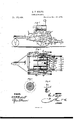
In the accompanying drawing, forming part of this specification, Figure 1 is a side eleva:
, tion of my improved steam-plow, and Fig. 2
is a plan view of the same. Fig. 3 shows a modification of the form of the circular cutters. Fig. 4 shows the manner of attaching plow-shares in place of rotary diggers.
A indicates the circular cutters, B the rotary or sod cutting and turning devices, and O the rotary cutters or blades, these several devices being arranged in the machine, from front to rear, in the order or succession named. A steam-boiler, D, is placed directly over the circular cutters A, and a crank-shaft, E, is arranged immediately in front of said cutters, at the rear end of the platform F. The crankshaft is operated by suitable pitman-connection with the pistons of the steam-cylinders G, as shown. The cutter A are in the form of disks with beveled edges, and keyed or otherwise suitably secured upon a shaft at a distance (in practice) of about nine inches apart. The spaces between the cutters are filled by narrow flanged drums, so that the cutters and drums together constitute alarger drum, having annular cutting ribs or teeth.
Large and small chain-pulleys I l are attached concentrically to each end of the drum. Chains K K connect the small pulleys I with the crank-shaft E of the engine, and chains L L connect the larger pulleys I with the shaft of the rotary diggers B, which is in turn similarly connected with the shaft of the radial cutters M. Broad-tread transportingwheels N are mounted loose on the journals of the bent axle 0, from which the main frame of the machine is supported. Pulleys P, of nearly the same size as the larger drum-pulleys I, are attached to the Wheels N, on the inner side thereof. Rotation is imparted to the said wheels by chains Q, which pass around pulleys on the crank-shaft E. Thus the rotation of the latter causes the rotation of the wheels N, and thereby the advance of the machine, as when proceeding along a highway, or from or to the lield, the machine being then supported entirely upon the said wheels N, and a front guiding-wheel, It, the several cutters and diggers being held olf the ground by raising the rear end of the supplementary frame S, in which their shafts have their bearings. The said frame is composed of parallel bars which are hinged at their front end to the crank-shaft E, and provided at the middle with vertical rack-bars T, which work in guides 0, attached to the main frame U. These rack-bars mesh with pinions on a cross-shaft, T, which may be rotated to raise or lower the frame S, by means of a wormgear, U, on a rod or shaft, V. The latter has a hand-wheel, W, attached to its front end, which is in suitable proximity to the platform F, upon which the engineer or operator stands.
The worm and pinions will lock the rackbars in any adjustment, and thereby hold the frame S elevated or lowered. When it is lowered, the weight of the machine is mainly supported upon the circular cutters, choppers, and diggers or shares and blades, and they are then brought into action upon the soil. Suitable provision is made for remov- I boards or plow-shares.
.ing the supplementary frame S and its attachments, in order to convert the machine into a portable engine to be utilized for various purposes or operations upon the farm. The diggers are essentially rectangular in outline, and the upper left-hand corner is bent or curved inward on the face side. They are also attached to disks Y by means of forked arms, so as to range in spiral lines around the shaft A.
The form and arrangement of the diggers enable them, as they revolve, to severally make, in regular succession, a diagonal drawcut across the strips or slices into which the ground has been cut by the circular cutters which precede them, and also to dislodge the pieces so cut and turn them over in the same manner as the mold-board of a plow turns a continuous furrow slice. The form of the diggers also enables them to clear themselves of the severed pieces of earth, so that they are not impeded in their revolution by earrying up the weight of said pieces, as they would be if made flat or straight on the face.
The diggers begin to cut at one end, and continue to do so until the entire cutting-edge has entered the soil, and they at the same time press against the piece being cut, acting thus in the'nature of both a colter and plowshare. The diggers are so arranged that they begin their cut in the slits made by the circular cutters, and act upon the sod or earth in the manner of shears upon cloth, the out being begun by the corner of the digger at one edge of the strip of sod, and gradually carried across the strip, thus severing a piece of sod or earth with comparatively small expenditure of force. The rear cutters or blades are set radially around their shaft, and have a thin curved edge and thick back. They rotate at much higher speed, and following. as they do, immediately behind the diggers, they cut, tear, and pulverize the pieces of soil thrown up by the latter.
From the foregoing description it will be understood that the earth is cut into strips or slices by the circular cutters; that the diggers, following immediately after and rotating more rapidly than said circular cutters, divide the strips, or slices, or sod, or soil into small pieces, which are simultaneously dislodged, raised, and turned over, the diggers operating first as draw-knives, and next as mold- The soil is thus left in condition to be acted on by the radial blades, which, rotating with much greater rapidity than the diggers, divide and tear the pieces cut off by the diggers, and reduce the soil to an approximatelypulverulent condi tion, thus leavingit; in fine tilth, and render-Q ing the use of a harrow, orfurther processof cultivation, entirely unnecessary as a prepara tion for any kind of crop.
It is apparentflthat the drum properwill 1 prevent the cutters A sinking too deep in soft earth while cultivating the soil, performing in. I such case the function of transporting-wheels. having a broad tread. To enable the circular cutters to take a better hold in the earth,
and have more tractive power without in pairing the performance of their function, they maybe constructed with a scalloped edge, as shown in-Fig. 3. The advance of the ma chine when at work is caused mainly by the rotation of the rotary diggers or plows, but the circular cutters and blades aid to a certain extent. Thus all the cultivating devices co-operate in propelling the machine in place of retarding it. I am hence enabled to propel th'e machine with 'less expenditure of power than has been heretofore required for 1 machines of this class, and no more weight need be sustained by the main transportingwheels than may be desired, as that eanbe periphery of the'drum which is geared or connected with the driving-shaft, the adjustable frame S, the transporting-wheels, and main frame A, said partsbeing combined, as shown and described, to operate as and for the pur-I pose specified.
2. The rotary diggers arranged in relation to the circularcutters, as shown and described,
so as to begin theircut in the slit made'by said cutters, as specified.
3. The combination; of the adjustable frame S, hinged at the front end, and carrying the rotary cutters A, diggers B, and blades 0, and i the rack-bars. and worm-gear combined, as
shown and described,ffor the purpose speci- Witnesses: A. W. HART,"
SoLoN C. KEMON.
Publications (1)
| Publication Number | Publication Date |
|---|---|
| US185484A true US185484A (en) | 1876-12-19 |
Family
ID=2254890
Family Applications (1)
| Application Number | Title | Priority Date | Filing Date |
|---|---|---|---|
| US185484D Expired - Lifetime US185484A (en) | Improvement in steam-plows |
Country Status (1)
| Country | Link |
|---|---|
| US (1) | US185484A (en) |
Cited By (2)
| Publication number | Priority date | Publication date | Assignee | Title |
|---|---|---|---|---|
| US4051902A (en) * | 1975-01-07 | 1977-10-04 | Lely Cornelis V D | Soil cultivating implements |
| US20100003687A1 (en) * | 2008-07-01 | 2010-01-07 | 454 Life Sciences Corporation | System and method for detection of HIV tropism variants |
-
0
- US US185484D patent/US185484A/en not_active Expired - Lifetime
Cited By (2)
| Publication number | Priority date | Publication date | Assignee | Title |
|---|---|---|---|---|
| US4051902A (en) * | 1975-01-07 | 1977-10-04 | Lely Cornelis V D | Soil cultivating implements |
| US20100003687A1 (en) * | 2008-07-01 | 2010-01-07 | 454 Life Sciences Corporation | System and method for detection of HIV tropism variants |
Similar Documents
| Publication | Publication Date | Title |
|---|---|---|
| US2455148A (en) | Motor-driven rotary digging apparatus | |
| US2228389A (en) | Basin machine | |
| US185484A (en) | Improvement in steam-plows | |
| EP0074778A1 (en) | Soil working apparatus | |
| US1301043A (en) | Agricultural implement. | |
| US1088075A (en) | Cultivating-machine. | |
| US2669067A (en) | Method of cultivating row crops | |
| US1566471A (en) | Rotary plowshare pulverizer | |
| US1349858A (en) | Soil-pulverizer | |
| US1740321A (en) | Chopper and cultivator | |
| US2514395A (en) | Tilling implement with concentric helical cutters | |
| US1328800A (en) | Soil-pulverizer | |
| US2364449A (en) | Agricultural implement | |
| US1360868A (en) | Cultivator | |
| US2040068A (en) | Apparatus for preparing soil for seeding | |
| US3130796A (en) | Earth conditioning implement | |
| US738597A (en) | Ditching-machine. | |
| US349807A (en) | Steam plowing | |
| US2483767A (en) | Soil pulverizer | |
| US1023043A (en) | Soil-tilling machine. | |
| US2092553A (en) | Plow | |
| US259894A (en) | Oren b | |
| RU2622737C1 (en) | Combined unit for preparation of soils | |
| US2694967A (en) | Row crop cultivator | |
| US335082A (en) | Combined plow and harrow |