US1854844A - Pulverizer - Google Patents
Pulverizer Download PDFInfo
- Publication number
- US1854844A US1854844A US395545A US39554529A US1854844A US 1854844 A US1854844 A US 1854844A US 395545 A US395545 A US 395545A US 39554529 A US39554529 A US 39554529A US 1854844 A US1854844 A US 1854844A
- Authority
- US
- United States
- Prior art keywords
- paddle
- trunnions
- pulverizer
- hook
- trunnion
- Prior art date
- Legal status (The legal status is an assumption and is not a legal conclusion. Google has not performed a legal analysis and makes no representation as to the accuracy of the status listed.)
- Expired - Lifetime
Links
- 230000035939 shock Effects 0.000 description 7
- 239000000463 material Substances 0.000 description 6
- 238000010276 construction Methods 0.000 description 4
- 230000002159 abnormal effect Effects 0.000 description 2
- 238000010298 pulverizing process Methods 0.000 description 2
- 229910000851 Alloy steel Inorganic materials 0.000 description 1
- 238000003754 machining Methods 0.000 description 1
- 239000002184 metal Substances 0.000 description 1
- 229910052751 metal Inorganic materials 0.000 description 1
- 238000006467 substitution reaction Methods 0.000 description 1
Images
Classifications
-
- B—PERFORMING OPERATIONS; TRANSPORTING
- B02—CRUSHING, PULVERISING, OR DISINTEGRATING; PREPARATORY TREATMENT OF GRAIN FOR MILLING
- B02C—CRUSHING, PULVERISING, OR DISINTEGRATING IN GENERAL; MILLING GRAIN
- B02C13/00—Disintegrating by mills having rotary beater elements ; Hammer mills
- B02C13/26—Details
- B02C13/28—Shape or construction of beater elements
Definitions
- the present invention is particularly directed to the improvement of the mounting and construction of revolving paddles used in pulverizers. It is desirable that the paddles be of simple construction and capable of opposing the shock and centrifugal force and of such geometrical form that they may be either cast, or forged and require no machining in order to put them 1n use, thereby permitting the use of chilled lron, alloy steel, or any other material of which the resistance to wear is such as to make it not readily machinable.
- paddles be readily removable so that substitution of paddles may be made as they become worn.
- Fig. 1 is a side elevation of a pulverizer, partly in section to better show construction.
- Fig. 2 a section on the line 22 in Fig. 3.
- Fig. 3 a section on the line 3-3 in Fig. 2.
- Fig. 4a section of a detached paddle on the line 3-3 in Fig. 2.
- 1 marks the pulverizer base, 2 the pulverizer case, 3 the rotating shaft, ands discs on which the pulverizer paddles are mounted, these discs being fixed on the shaft.
- Paddles 5 are provided with slots 6, said slots receiving the discs 4..
- Each paddle has hooks 7.
- the books are formed by notches 7a which are arranged in the walls of the paddle at the sides of the slots.
- Trunnions 8 are fixed on the discs and the books 7 are hooked on to these trunnions.
- the base 9 of the slot is outwardly inclined from the front face of the paddle.
- the outwardly extending facing edge 10 of the hook 7 is so directed with relation to the base 9 that when the paddle is turned to the rear the edge 10 does not extend outwardly from a direction parallel with the edge of the disc.
- the disc is cut away at 4a providing a flattened portion opposite the trunnions 8 so that when the paddle is swung to the rear the edge 10 may be brought at least parallel with this flattened portion so that the hooks may be readily assembled on the trunnions 8.
- the paddles may be readily assembled by merely inclining them to the rear and moving the hooks into place and may then be swung out to their operative, or radial position, as shown in Fig.3, the front part of the base 9 engaging the disc and limiting this forward movement of the paddles.
- a cotter pin 11 extends through the discs and forms a stop opposing the backward movement of the paddle from this operative position.
- projections 12 are provided at the rear of the paddle which engage the cotter pin.
- the cotter pin is purposely made of rather fragile construction so that if the paddle meets with any obstruction such as would be apt to injure the apparatus the cotter pin is sheared off, thus permitting the paddle to swing back and clear the obstruction.
- the cotter pin is also provided with means by which it may be readily removed so as to permit of the paddle being swung back and thus unhooked.
- the walls 13 are provided outside the hooks, thus covering the trunnions and fully protecting them against the impact of material as the paddle is moved forward.
- the cotter pin is also arranged directly in the rear of the proj ecting walls of the paddle and is, therefore,
- a pulverizer the combination of a rotating carrier plate; trunnions projecting from the plate; and a paddle having a slot receiving the carrier plate, the sides of the slot having hooks formed therein engaging the trunnion, the base of the slot and the face of the hook having a distance apart corresponding to the distance between the trunnion and the edge of the plate permitting the engagement of the hook on the trunnion.
- apulverizer the combination of a rotating carrier plate; trunnions projecting from the plate; and a paddle having a slot receiving the carrier plate, the sides of the slot having hooks formed therein. engaging the trunnion, the base of the slot being illclined and the face of the hook similarily inclined to the face of the paddle and having a distance apart corresponding to the distance between the edge of the plate and the trunnion to permit the engagement of the hook on the trunnion with the paddle inclined to the radial position, said hook and base having a relation locking the paddle against disengagement with the paddle radially disose a.
- a pulverizer In a pulverizer, thecombination of a rotating carrier plate; trunnions projecting from the plate; a paddle having a slot receiving the carrier plate, the sides of the slot having hooks formed therein engaging the trunnion, the base of the slot being inclined and the face of the hook similarly inclined to the face of the paddle and having a distance apart corresponding to the distance between the edge of the plate and the trunnion to permit the engagement of the hook on the trunnion with the paddle inclined to the radial position, said hook and base having a relation locking the paddle against disengagement with the paddle radially disposed; and means locking the paddle in a radial position.
- a pulverizer the combination of a rotating carrier plate; trunnions projecting from the plate; a paddle having a slot receiving the carrier plate, the sides of the slot having hooks formed therein engaging the trunnion, the base of the slot being inclined and the face of the hook similarly inclined to the face of the paddle and having a distance apart corresponding to the distance between the edge of the plate and the trunnion to permit the engagement of the hook on the trunnion with the paddle inclined to the radial position, said hook and base having a relation locking the paddle against disengagement with the paddle radially disposed; and means readily breakable locking the paddle in a radial position.
- a rotating carrier plate trunnions projecting from the plate; a paddle having a slot receiving the carrier plate, the sides of the slot having hooks formed therein engaging the trunnion, the base of the slot being inclined and the face of the hook similarly inclined to the face of the paddle and having a distance apart corresponding to the distance between the edge of the plate and the trunnion to permit the engagement of thehook on the trunnion with the paddle inclined to the radial position, said hook and base having a relation locking the paddle against disengagement with the paddle radially disposed; and a cotter pin extending through the plate locking the paddle in a radial position.
- a pulverizer the combination of a rotating carrier plate; trunnions projecting from the plate; and a paddle having a slot receiving the carrier plate, the sides of the slot having hooks formed therein engaging the trunnion, the walls at the sides of the paddle joining the sides of the hooks and covering the ends of the trunnion.
- a rotating carrier trunnions extending from the carrier; a paddle straddling the carrier and pivotally mounted on the trunnions and removable with the trunnions in place, said trunnions sustaining the entire centrifugal force; and a removable means locking the paddle in operative position.
- a pulverizer the combination of arotating carrier; trunnions extending from the carrier; a paddle pivotally mounted on the trunnions and removable with the trunnions in place, said trunnions sustainingv the entire centrifugal force; and a readily breakable means locking the paddle in operative position.
- a pulverizer the combination of a rotating carrier; trunnions extending from the carrier; a paddle pivotally mounted on the trunnions, said trunnions sustaining the centrifugal force on the paddle, said paddle engaging the carrier to limit its forward position; and a removable means engaging the paddle to limit its rearward movement.
- a paddle for pulverizing machines having a hook for engagement with a rotating carrier, the openings to the hook being closed by the walls of the paddle except at the rear.
- a paddle for pulverizing machines having a hook adapted to straddle a rotating carrier and engage the same,'the openings to the hook being closed by the walls of the paddle except at the rear.
- a pulverizer the combination of a rotating carrier; a paddle; a pivotal connection between the carrier and paddle, said connection'permitting the removal of the paddle when inwardly swung; and removable means loclnng the paddle on the connection, said means permitting a pivotal movement of the paddle when subjected to abnormal shock, said paddle having walls protecting the connection and locking means from wear through impact on the paddle.
- a pulverizer the combination of a rotating carrier; trunnions extending from the carrier; a paddle straddling the carrier pivotally mounted on the trunnions and removable therefrom with the trunnions in place, said trunnions sustaining the entire centrifugal force; and removable means locking the paddle in operative position, said paddle having walls protecting the trunnions and the removable locking means from wear through impact on the paddle as the carrier rotates.
Landscapes
- Engineering & Computer Science (AREA)
- Food Science & Technology (AREA)
- Crushing And Pulverization Processes (AREA)
- Crushing And Grinding (AREA)
Description
April 19, 1932. G. H. KAEMMERLING PULVERI ZER Filed Sept. 27, 1929 INVENTOR AT ORNEYS.
Patented Apr. 19, 1932 UNITED STATES PATENT OFFICE mm-ems...
GUSTAV H. KAEMMERLING, OF ERIE, PENNSYLVANIA, ASSIGNOR TO ERIE CITY IRON WORKS, OF ERIE, PENNSYLVANIA, A CORPORATION OF PENNSYLVANIA PULVERIZER Application filed September 27, 1929. Serial No. 395,545.
The present invention is particularly directed to the improvement of the mounting and construction of revolving paddles used in pulverizers. It is desirable that the paddles be of simple construction and capable of opposing the shock and centrifugal force and of such geometrical form that they may be either cast, or forged and require no machining in order to put them 1n use, thereby permitting the use of chilled lron, alloy steel, or any other material of which the resistance to wear is such as to make it not readily machinable.
It is also desirable to pivotally mount such paddles and lock them in operative position as against normal shocks, but permit them to swing under abnormal shocks so as to relieve the stress on the material under such shocks.
This may be accomplished, and is accom-' plished in the present invention by making such operative locking means readily breakable under shock.
It is also desirable to house the operating parts by the material of the paddle so that materials readily machined and of ordinary hardness may be used, the wear thus being confined in a large measure to the paddle itself.
It is also desirable that such paddles be readily removable so that substitution of paddles may be made as they become worn.
Features and details of the invention will appear from the specification and claims.
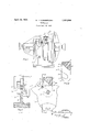
A preferred embodiment of the invention is illustrated in the accompanying drawings as follows Fig. 1 is a side elevation of a pulverizer, partly in section to better show construction.
Fig. 2 a section on the line 22 in Fig. 3.
Fig. 3 a section on the line 3-3 in Fig. 2. i Fig. 4a section of a detached paddle on the line 3-3 in Fig. 2.
1 marks the pulverizer base, 2 the pulverizer case, 3 the rotating shaft, ands discs on which the pulverizer paddles are mounted, these discs being fixed on the shaft.
Paddles 5 are provided with slots 6, said slots receiving the discs 4.. Each paddle has hooks 7. The books are formed by notches 7a which are arranged in the walls of the paddle at the sides of the slots.
Trunnions 8 are fixed on the discs and the books 7 are hooked on to these trunnions. The base 9 of the slot is outwardly inclined from the front face of the paddle. The outwardly extending facing edge 10 of the hook 7 is so directed with relation to the base 9 that when the paddle is turned to the rear the edge 10 does not extend outwardly from a direction parallel with the edge of the disc. Preferably the disc is cut away at 4a providing a flattened portion opposite the trunnions 8 so that when the paddle is swung to the rear the edge 10 may be brought at least parallel with this flattened portion so that the hooks may be readily assembled on the trunnions 8.
The paddles, therefore, may be readily assembled by merely inclining them to the rear and moving the hooks into place and may then be swung out to their operative, or radial position, as shown in Fig.3, the front part of the base 9 engaging the disc and limiting this forward movement of the paddles.
In order to hold the paddle in this operative position as against normal shocks a cotter pin 11 extends through the discs and forms a stop opposing the backward movement of the paddle from this operative position. Preferably projections 12 are provided at the rear of the paddle which engage the cotter pin. The cotter pin is purposely made of rather fragile construction so that if the paddle meets with any obstruction such as would be apt to injure the apparatus the cotter pin is sheared off, thus permitting the paddle to swing back and clear the obstruction. The cotter pin is also provided with means by which it may be readily removed so as to permit of the paddle being swung back and thus unhooked.
In order to protect the ends of the trunnions which ordinarily would be of softer or more machinable metal than the paddle the walls 13 are provided outside the hooks, thus covering the trunnions and fully protecting them against the impact of material as the paddle is moved forward. The cotter pin is also arranged directly in the rear of the proj ecting walls of the paddle and is, therefore,
fully protected against the action of material on which the paddle is operating. With this construction, therefore, the hook openings are closed in every direction except toward the rear so that the operating parts are fully protected.
What I claim as new is 1. In a pulverizer, the combination of a rotating carrier plate; trunnions projecting from the plate; and a paddle having a slot receiving the carrier plate, the sides of the slot having hooks formed therein engaging the trunnion.
2. In a pulverizer, the combination of a rotating carrier plate; trunnions projecting from the plate; and a paddle having a slot receiving the carrier plate, the sides of the slot having hooks formed therein engaging the trunnion, the base of the slot and the face of the hook having a distance apart corresponding to the distance between the trunnion and the edge of the plate permitting the engagement of the hook on the trunnion.
3. In apulverizer, the combination of a rotating carrier plate; trunnions projecting from the plate; and a paddle having a slot receiving the carrier plate, the sides of the slot having hooks formed therein. engaging the trunnion, the base of the slot being illclined and the face of the hook similarily inclined to the face of the paddle and having a distance apart corresponding to the distance between the edge of the plate and the trunnion to permit the engagement of the hook on the trunnion with the paddle inclined to the radial position, said hook and base having a relation locking the paddle against disengagement with the paddle radially disose a. In a pulverizer, thecombination of a rotating carrier plate; trunnions projecting from the plate; a paddle having a slot receiving the carrier plate, the sides of the slot having hooks formed therein engaging the trunnion, the base of the slot being inclined and the face of the hook similarly inclined to the face of the paddle and having a distance apart corresponding to the distance between the edge of the plate and the trunnion to permit the engagement of the hook on the trunnion with the paddle inclined to the radial position, said hook and base having a relation locking the paddle against disengagement with the paddle radially disposed; and means locking the paddle in a radial position.
5. In a pulverizer, the combination of a rotating carrier plate; trunnions projecting from the plate; a paddle having a slot receiving the carrier plate, the sides of the slot having hooks formed therein engaging the trunnion, the base of the slot being inclined and the face of the hook similarly inclined to the face of the paddle and having a distance apart corresponding to the distance between the edge of the plate and the trunnion to permit the engagement of the hook on the trunnion with the paddle inclined to the radial position, said hook and base having a relation locking the paddle against disengagement with the paddle radially disposed; and means readily breakable locking the paddle in a radial position.
6. In a pulverizer, the combination of a rotating carrier plate; trunnions projecting from the plate; a paddle having a slot receiving the carrier plate, the sides of the slot having hooks formed therein engaging the trunnion, the base of the slot being inclined and the face of the hook similarly inclined to the face of the paddle and having a distance apart corresponding to the distance between the edge of the plate and the trunnion to permit the engagement of thehook on the trunnion with the paddle inclined to the radial position, said hook and base having a relation locking the paddle against disengagement with the paddle radially disposed; and a cotter pin extending through the plate locking the paddle in a radial position.
7 In a pulverizer, the combination of a rotating carrier plate; trunnions projecting from the plate; and a paddle having a slot receiving the carrier plate, the sides of the slot having hooks formed therein engaging the trunnion, the walls at the sides of the paddle joining the sides of the hooks and covering the ends of the trunnion.
8. In a pulverizer, the combination of a rotating carrier; trunnions extending from the carrier; a paddle straddling the carrier and pivotally mounted on the trunnions and removable with the trunnions in place, said trunnions sustaining the entire centrifugal force; and a removable means locking the paddle in operative position.
9. In a pulverizer, the combination of arotating carrier; trunnions extending from the carrier; a paddle pivotally mounted on the trunnions and removable with the trunnions in place, said trunnions sustainingv the entire centrifugal force; and a readily breakable means locking the paddle in operative position. v
10. In a pulverizer, the combination of a rotating carrier; trunnions extending from the carrier; a paddle pivotally mounted on the trunnions, said trunnions sustaining the centrifugal force on the paddle, said paddle engaging the carrier to limit its forward position; and a removable means engaging the paddle to limit its rearward movement.
11. A paddle for pulverizing machines having a hook for engagement with a rotating carrier, the openings to the hook being closed by the walls of the paddle except at the rear.
12. A paddle for pulverizing machines having a hook adapted to straddle a rotating carrier and engage the same,'the openings to the hook being closed by the walls of the paddle except at the rear.
13. In a pulverizer, the combination of a rotating carrier; a paddle; a pivotal connection between the carrier and paddle, said connection'permitting the removal of the paddle when inwardly swung; and removable means loclnng the paddle on the connection, said means permitting a pivotal movement of the paddle when subjected to abnormal shock, said paddle having walls protecting the connection and locking means from wear through impact on the paddle.
14;. In a pulverizer, the combination of a rotating carrier; trunnions extending from the carrier; a paddle straddling the carrier pivotally mounted on the trunnions and removable therefrom with the trunnions in place, said trunnions sustaining the entire centrifugal force; and removable means locking the paddle in operative position, said paddle having walls protecting the trunnions and the removable locking means from wear through impact on the paddle as the carrier rotates.
In testimony whereof I have hereunto set my hand.
GUSTAV H. KAEMMERLING.
Priority Applications (1)
| Application Number | Priority Date | Filing Date | Title |
|---|---|---|---|
| US395545A US1854844A (en) | 1929-09-27 | 1929-09-27 | Pulverizer |
Applications Claiming Priority (1)
| Application Number | Priority Date | Filing Date | Title |
|---|---|---|---|
| US395545A US1854844A (en) | 1929-09-27 | 1929-09-27 | Pulverizer |
Publications (1)
| Publication Number | Publication Date |
|---|---|
| US1854844A true US1854844A (en) | 1932-04-19 |
Family
ID=23563494
Family Applications (1)
| Application Number | Title | Priority Date | Filing Date |
|---|---|---|---|
| US395545A Expired - Lifetime US1854844A (en) | 1929-09-27 | 1929-09-27 | Pulverizer |
Country Status (1)
| Country | Link |
|---|---|
| US (1) | US1854844A (en) |
Cited By (22)
| Publication number | Priority date | Publication date | Assignee | Title |
|---|---|---|---|---|
| US2705596A (en) * | 1950-10-23 | 1955-04-05 | H R Marsden Ltd | Machine for breaking stone and similar material by means of impact |
| US3473742A (en) * | 1966-10-25 | 1969-10-21 | Jacksonville Blow Pipe Co | Machine for the punching and cutting of wood |
| US4146185A (en) * | 1977-11-23 | 1979-03-27 | Waste Management, Inc. | Shredder hammer |
| US20070023554A1 (en) * | 2005-06-11 | 2007-02-01 | Young Robert T | Hammermill hammer |
| US20080011890A1 (en) * | 2005-06-11 | 2008-01-17 | Young Roger T | Hammermill hammer |
| US20110042498A1 (en) * | 2004-08-11 | 2011-02-24 | Young Roger T | Hammer |
| US8033490B1 (en) | 2004-08-11 | 2011-10-11 | Genesis Iii, Inc. | Hammer |
| US8141804B1 (en) | 2009-05-22 | 2012-03-27 | Genesis Iii, Inc. | Curved hammer |
| US8800903B1 (en) | 2011-08-03 | 2014-08-12 | Roger T. Young | Multi-connector hammer and protective arm |
| RU179319U1 (en) * | 2017-10-02 | 2018-05-08 | Открытое акционерное общество "НПО Центр" | WORKING BODY OF THE DEVICE FOR SHOCK AND CENTRIFUGAL GRINDING |
| USD839934S1 (en) | 2017-12-06 | 2019-02-05 | Roger Young | Swing hammer |
| USD840447S1 (en) | 2017-12-06 | 2019-02-12 | Roger Young | Swing hammer |
| US10201814B1 (en) | 2004-08-11 | 2019-02-12 | Genesis Iii, Inc. | Hammer |
| US10207274B1 (en) | 2017-08-21 | 2019-02-19 | Roger Young | Non-forged hammermill hammer |
| USD861048S1 (en) | 2017-12-06 | 2019-09-24 | Roger Young | Swing hammer |
| US10478824B2 (en) | 2017-08-21 | 2019-11-19 | Bliss Industries, Llc | System and method for installing hammers |
| US10486160B2 (en) | 2017-08-21 | 2019-11-26 | Bliss Industries, Llc | Method of replacing hammers and spacers |
| US10610870B2 (en) | 2017-08-21 | 2020-04-07 | Bliss Industries, Llc | Hot and cold forming hammer and method of assembly |
| USD905136S1 (en) | 2018-03-05 | 2020-12-15 | Bliss Industries, Llc | Hammermill hammer |
| US11839879B2 (en) | 2020-10-09 | 2023-12-12 | Genesis Iii, Inc. | Hammer |
| US12138630B2 (en) | 2017-08-21 | 2024-11-12 | Bliss Industries, Llc | Hammermill hammer |
| US12319388B2 (en) | 2020-04-08 | 2025-06-03 | JJB Solutions LLC | Load lifter assembly |
-
1929
- 1929-09-27 US US395545A patent/US1854844A/en not_active Expired - Lifetime
Cited By (39)
| Publication number | Priority date | Publication date | Assignee | Title |
|---|---|---|---|---|
| US2705596A (en) * | 1950-10-23 | 1955-04-05 | H R Marsden Ltd | Machine for breaking stone and similar material by means of impact |
| US3473742A (en) * | 1966-10-25 | 1969-10-21 | Jacksonville Blow Pipe Co | Machine for the punching and cutting of wood |
| US4146185A (en) * | 1977-11-23 | 1979-03-27 | Waste Management, Inc. | Shredder hammer |
| US8960581B1 (en) | 2004-08-11 | 2015-02-24 | Genesis Iii, Inc. | Hammer |
| US11103875B1 (en) | 2004-08-11 | 2021-08-31 | Genesis Iii, Inc. | Hammer |
| US10201814B1 (en) | 2004-08-11 | 2019-02-12 | Genesis Iii, Inc. | Hammer |
| US11185866B2 (en) | 2004-08-11 | 2021-11-30 | Genesis Iii, Inc. | Hammer |
| US20110042498A1 (en) * | 2004-08-11 | 2011-02-24 | Young Roger T | Hammer |
| US8033490B1 (en) | 2004-08-11 | 2011-10-11 | Genesis Iii, Inc. | Hammer |
| US9737894B1 (en) | 2004-08-11 | 2017-08-22 | Genesis Iii, Inc. | Hammer |
| US8708263B2 (en) | 2004-08-11 | 2014-04-29 | Roger T. Young | Hammer |
| US9566584B2 (en) | 2004-08-11 | 2017-02-14 | Genesis Iii, Inc. | Hammer |
| US7621477B2 (en) * | 2005-06-11 | 2009-11-24 | Genesis Iii, Inc. | Hammermill hammer |
| US7559497B2 (en) * | 2005-06-11 | 2009-07-14 | Genesis Iii, Inc. | Hammermill hammer |
| US20080011890A1 (en) * | 2005-06-11 | 2008-01-17 | Young Roger T | Hammermill hammer |
| US20070023554A1 (en) * | 2005-06-11 | 2007-02-01 | Young Robert T | Hammermill hammer |
| US8998120B1 (en) | 2009-05-22 | 2015-04-07 | Genesis Iii, Inc. | Curved hammer |
| US8141804B1 (en) | 2009-05-22 | 2012-03-27 | Genesis Iii, Inc. | Curved hammer |
| US11759789B1 (en) | 2009-05-22 | 2023-09-19 | Genesis Iii, Inc. | Curved hammer |
| US10857540B1 (en) | 2009-05-22 | 2020-12-08 | Genesis Iii, Inc. | Curved hammer |
| US9358546B1 (en) | 2011-08-03 | 2016-06-07 | Genesis Iii, Inc. | Multi-connector hammer and protective arm |
| US8800903B1 (en) | 2011-08-03 | 2014-08-12 | Roger T. Young | Multi-connector hammer and protective arm |
| US11396021B2 (en) | 2011-08-03 | 2022-07-26 | Genesis Iii, Inc. | Multi-connector hammer |
| US10486159B2 (en) | 2011-08-03 | 2019-11-26 | Genesis Iii, Inc. | Multi-connector hammer |
| US10507468B2 (en) | 2017-08-21 | 2019-12-17 | Bliss Industries, Llc | Non-forged hammermill hammer |
| US10207274B1 (en) | 2017-08-21 | 2019-02-19 | Roger Young | Non-forged hammermill hammer |
| US10478824B2 (en) | 2017-08-21 | 2019-11-19 | Bliss Industries, Llc | System and method for installing hammers |
| US12138630B2 (en) | 2017-08-21 | 2024-11-12 | Bliss Industries, Llc | Hammermill hammer |
| US10610870B2 (en) | 2017-08-21 | 2020-04-07 | Bliss Industries, Llc | Hot and cold forming hammer and method of assembly |
| US10486160B2 (en) | 2017-08-21 | 2019-11-26 | Bliss Industries, Llc | Method of replacing hammers and spacers |
| RU179319U1 (en) * | 2017-10-02 | 2018-05-08 | Открытое акционерное общество "НПО Центр" | WORKING BODY OF THE DEVICE FOR SHOCK AND CENTRIFUGAL GRINDING |
| USD857066S1 (en) | 2017-12-06 | 2019-08-20 | Roger Young | Swing hammer |
| USD840447S1 (en) | 2017-12-06 | 2019-02-12 | Roger Young | Swing hammer |
| USD839934S1 (en) | 2017-12-06 | 2019-02-05 | Roger Young | Swing hammer |
| USD861048S1 (en) | 2017-12-06 | 2019-09-24 | Roger Young | Swing hammer |
| USD905136S1 (en) | 2018-03-05 | 2020-12-15 | Bliss Industries, Llc | Hammermill hammer |
| US12319388B2 (en) | 2020-04-08 | 2025-06-03 | JJB Solutions LLC | Load lifter assembly |
| US11839879B2 (en) | 2020-10-09 | 2023-12-12 | Genesis Iii, Inc. | Hammer |
| US12186759B2 (en) | 2020-10-09 | 2025-01-07 | Genesis Iii, Inc. | Hammer |
Similar Documents
| Publication | Publication Date | Title |
|---|---|---|
| US1854844A (en) | Pulverizer | |
| US2663505A (en) | Rotary impact hammer for pulverizers | |
| US3367585A (en) | Replaceable tip member for a two-part hammer | |
| US2015581A (en) | Pulverizer hammer | |
| US3074657A (en) | Impact crushing apparatus | |
| US1761083A (en) | Pulverizing apparatus | |
| USRE14865E (en) | Rotary hammer | |
| US2534301A (en) | Impact hammer with attached wear member | |
| US3146961A (en) | Impact hammer | |
| US4821970A (en) | Impact crusher | |
| US4136833A (en) | Renewable tip hammer for a crusher | |
| US1717759A (en) | Hammer for rotary crushers | |
| US2310758A (en) | Impact member for impact crushers | |
| US3058679A (en) | Impact crusher | |
| US3236463A (en) | Centrifugal hammer and renewable tip | |
| US2716526A (en) | Renewable tip pulverizer hammer | |
| US2588900A (en) | Crusher-roll covering element | |
| US3352064A (en) | Lock system for blasting-machine blades | |
| US1456987A (en) | Hammer | |
| US3355113A (en) | Striking plate for disintegrating mill | |
| US2844331A (en) | Impact crusher | |
| US4397426A (en) | Shoe bracket assembly for vertical shaft impact crushing machines | |
| US1925806A (en) | Pulverizer | |
| US2325605A (en) | Impact member for impact crushers and securing means therefor | |
| US3110449A (en) | Breaker plate structure |