US1854835A - Treating hydrocarbon oils - Google Patents
Treating hydrocarbon oils Download PDFInfo
- Publication number
- US1854835A US1854835A US252071A US25207128A US1854835A US 1854835 A US1854835 A US 1854835A US 252071 A US252071 A US 252071A US 25207128 A US25207128 A US 25207128A US 1854835 A US1854835 A US 1854835A
- Authority
- US
- United States
- Prior art keywords
- coil
- oil
- line
- cracking
- gasoline
- Prior art date
- Legal status (The legal status is an assumption and is not a legal conclusion. Google has not performed a legal analysis and makes no representation as to the accuracy of the status listed.)
- Expired - Lifetime
Links
Images
Classifications
-
- C—CHEMISTRY; METALLURGY
- C10—PETROLEUM, GAS OR COKE INDUSTRIES; TECHNICAL GASES CONTAINING CARBON MONOXIDE; FUELS; LUBRICANTS; PEAT
- C10G—CRACKING HYDROCARBON OILS; PRODUCTION OF LIQUID HYDROCARBON MIXTURES, e.g. BY DESTRUCTIVE HYDROGENATION, OLIGOMERISATION, POLYMERISATION; RECOVERY OF HYDROCARBON OILS FROM OIL-SHALE, OIL-SAND, OR GASES; REFINING MIXTURES MAINLY CONSISTING OF HYDROCARBONS; REFORMING OF NAPHTHA; MINERAL WAXES
- C10G9/00—Thermal non-catalytic cracking, in the absence of hydrogen, of hydrocarbon oils
- C10G9/14—Thermal non-catalytic cracking, in the absence of hydrogen, of hydrocarbon oils in pipes or coils with or without auxiliary means, e.g. digesters, soaking drums, expansion means
Definitions
- the invention seeks to provide a process by which an oil containing gasoline or naphtha fractions may be treated to recover these fractions as well as to convert other higher boiling fractions contained in the oil into gasoline or naphtha,products.
- the invention contemplates a process wherein crude petroleum is stripped of its natural gasoline or naphtha content, the resultant crude residuum subjected to cracking for the production of lower boiling products, and the tar or residue produced in the cracking operation subjected to vaporization to recover therefrom any gasoline or other light products contained therein and also to recover therefrom a distillate suitable for use 1n the cracking operation.
- the invention furthermore contemplates a process wherein crude oil is stripped of its gasoline or naphtha content, the resultant residue subjected to cracking to yield lower boiling products, the tar or residue produced in the cracln'ng operation distilled to free it of any gasoline or naphtha contained therein, and to distill off a heavier condensate, such as gas oil, and this heavier condensate cyclio ly returned to the cracking zone.
- crude oil is heated to vaporize off a given distillate such as gasoline, and the resultant crude residuum is subjected to cracking temperatures -under superatmospheric pressures to thereby efiect conversion of higher boiling hydrocarbons into lower boiling ones.
- a gasoline distillate is obtained from the evolved vaporsproduced' in the cracking operation-,and liquid or residue is withdrawn from the oil whichhas been subjected to cracking and this liquid is then subjected to a reduction in pressure and the contained heat in the liquid, with or with" out additional heating, such" as steam, operates to distill ofi any gasoline contained in the liquid and also additional distillates suitable for treatment latter distillate may cyclicly returned for conversion to gasoline 6, 1928.
- One method of operation the invention consists in obtaining hot condensate from the vapors evolved in distilling the residue or liquid from the cracln'ng operation, withdrawing the condensate from the dephlegmator at temperatures, preferably not substantially below its boiling point and conducting the hot condensate to the cracking zone.
- the invention furthermore vcontem lates a process wherein a hydrocarbon oil is slibjected to cracking under a superatmospheric pressure, the charge or a portion thereof formed by stripping a crude oil of its more volatile constituents to thereby form a residual oil which is charged to the cracking zone, the evolved vapors from'the cracking zone subjected to dephlegmation or fractionation to separate out the gasoline or naphtha distillate desired and a heavier condensate wwhich is to the cracking zone.
- the invention also has in view the provision of a heating coil for heating the initial crude charge, a vaporizing chamber into which this coil discharges, a second coil which is adapted to raise to a cracking temperature an oil charge which may include liquid obtained from the vaporizing chamber employed in treating the initial crude charge and a drum, orstill adapted to receive the oil from the second coil and in which the oil may be maintained at a cracking temperature for a time suflicient for the desired molecular transformation.
- the invention also, contemplates a process ,in which an expanslon or vaporizing contemplated by r chamber is provided for distilling ofi vaporizable constituents from residue drawn from the cracking still and the cyclic return of distillates obtained from such distillation to the heating coil in which the oil is raised to a cracking temperature.
- the invention furthermore contemplates theprovision of a suitable process and apparatus adapted for commercial operation on a large scale whereby a crude oil is charged. to the system, distilled to free itof its natural gasoline or naphtha content, the residue thus obtained subjected to cracking for the production of further quantities of gasoline, the residue obtained from the cracking operation distilled under reduced pressure to recover gasoline therefrom and to form heavier distillates, and the introduction of these distillates to the cracking zone, so as to thus sections of the obtain from a given crude charge a maximum production of gasoline.
- a pump serves to introduce'the charging stock, such as crude petroleum or other oil containing gasoline or naphtha constituents, through a charging line 11 into a heating coil 12.
- the Iatter coil isshown located in an economizer section or lower temperature portion of a furnace 13.
- the coil 12 -terminates in a transfer line 14 by which the heated oil is removed from the coil and discharged into a vaporizing chamber 15.
- Bafiles 16 are indicated in the chamber for assisting in the separation of the vapors from the liquid portions of the oil.
- the still 15 is provided with a fractionating or rectifying tower 17.
- a vapor line 18 conducts vapors from the still 15 to the fractionating tower 17 and a conducts liquid from the tower 17 back to the vaporizing chamber 15.
- a cooling coil 20 is shown for supplying cooling to the tower 17, and a vapor line 21 serves .to remove vapors from the tower and conduct them to a condenser 22 having an outlet pipe 23 by which the gasoline or naphtha fraction is discharged from the condenser.
- the stripped crude is removed from the still 15 and by means of a pipe 24 is conducted to a pump. 25 which forces the oil through a pipe 26 into a coil 27 located in the furnace 13.
- a burner 28 is indicated for supplying heat to the furnace, and the arrangement is such that the oil in transit through the coil 27 I'na be raised to a cracking temperature un er superatmospheric reflux condensate line 19 chambers as illusstripping still and the frach pressure. It is to be understood that the coil 12 is in a lower temperature section of the furnace 13 and does not receive the high temperature applied to the'coil 27.
- An auxiliary burner 29 is indicated for supplying additional heat to the coil 12 in case the waste gases that have'been employed in heating the coil 27 are inadequate for raising the temperture of the oil in the coil 12 to the desired egree.
- a transfer line 30 conducts the oil which has been heated to a cracking temperature in the coil 27 to a still or converted 31 wherein the oil is subjected to cracking or decomposition for the production of lower boiling point products. If desired a plurality or battery of stills or converters may be employed in lieu of the single still shown in the drawing.
- a vaporline 32 conducts evolved vapors from the still to a fractionating or rectifying tower 33.
- the tower is shown equipped with a coil 34 for supplying cooling thereto, and a vapor line 35 conducts the vapor fraction to a condenser coil 36" having an outlet pipe 37 communicating with a receiving drum 38.
- the receiving drum is preferably maintained under superatmospheric pressure, although the pressure in the drum may be reduced from that obtaining in the condenser 36.
- A'pipe 39 conducts the cracked gasoline or naphtha distillate to a tank 40.
- the condensate separated out in the-fractionating column 33 is conducted by a pipe 41'to a hot oil pump 42 which forces the hot condensate through a line 43 and thence into the coil 27, the line 43 preferably g with the coil 27 at a midpoint thereof so that the hot condensate may be combined with the charge introduced to the first part of the coil 27 at a temperature approximating the temperature of the charge with which it is combined.
- the tar or residue 31 is removed by a pipe 44 to a vaporizing or expansion chamber 45 which operates at a pressure reduced from that obtaining in the still 31.
- the line 44 is provided with a pressure reducing valve 46 so that the pressure on the oil may be reduced in the c amber 45 preferably to substantially atmospheric pressure.
- the chamber 45 is preferably insulated to prevent loss of heat and does not ordinarily require any heating means other than the hot oil entering thereinto.
- the evolved vapors pass through a vapor line 47 to a fraetionating or rectifying column 48 from which the gasoline or naphtha fraction is taken off through a vapor line 49 to a condenser coil 50.
- An outlet pipe 51 conducts the gasoline or naphtha condensate to the tank 40.
- Th the tower 48 constitutes what may be termed a light gas oil fraction and is removed by a pipe 52 to a heat exchanger 53 having a coolingLcoil 54.
- the liquid is conducted by a line 55 to a cooling coil 56 from which the e liquid separated out in formed in "the cracking 1 maybe readily w1 cooled liquid delivered through a transfer line 57 to a tank 58.
- Liquid or residue is drawn off from the vaporizing chamber '45 by a line 59 to a secondary distilling chamber 60.
- the va orizing chamber at a pressure slightly a ove atmospheric, say about ten pounds, so that the liquid residue drawn therefrom into the vaporizing chamber 60 which is held at substantiagiy atmospheric pressure.
- Live steam is intr uced into the chamber 60 by a pipe 61.
- the steam is preferably superheated and the gas oil fractions or other constituents which it is desired to distill off from the tar or residue, and which have not been vaporized in the chamber 45, are vaporized in the chamber 60.
- the vapors pass through a line 62 are combined with the strip tanks.
- the liquid collected in the separator 63 may be said to constitute a heavy gas oil fraction. It is drawn off through a plpe 68 and passed through a cooling coil 69 from which an outlet pipe 70 conducts the liquid to a tank 72.
- the residue which may be referred to as fuel oil, is drawn off from the vaporizing chamber 60 by a line 73 to a cooling coil 74 and passes thence into a fuel oil tank 75.
- the gas oil distillates contained in the tanks 58 and 72 are cycled back to the cracking system for retreatm'ent for conversion into asoline and to accomplish thista pump 7 6 is provided having its inlet line'7 7 arranged with branch lines 78 and .7 9 communicating respectively with the tanks 58 and 72.
- the branch lines are valved so that the pump may draw oil from either of the tanks or it may draw a mixture consisting of oil from bot line 80 of the pump oil constituents which have been recovere from the residue from the cracking system tained from the vaporizing c amber 15 and the combined stripped crude and recovered gas oil wherein they are raised to' a cracking temrature.
- the line 77 is shown extendin to the line 52 and provided with a branch dine 87 connected to the line 68 so that the gas oil fractions may be drawn directly from the fractionating tower 48 and the separator 63 and introduced into the coil 27 in a heated condition.
- condensate may from either or both of the separators 48 and 63 at temperatures not substantially below its boiling point and the hot oil combined liquid obtained in the crude d charge obdistillates are forced into the pipe 27 be withdrawn stripping apparatus for passage directly into the coil 27.
- the pipe 23 which receives the gasoline or naphtha distillate obtained from the crude stripping apparatus, or in other words, the natural gasoline content of the crude charge, is shown extending to the tank 40 so that the natural gasoline may be combined with the cracked gasoline obtained from the crackin system and the'cracked gasoline recovered from the tar stripping operation, but if, desired these distillates may be received in separate tanks. In some cases it is advantaeous to form several cuts or fractions from e vapors'from the stripping still 15. Thus a gas line and a kerosene cut may be made in ad "tion to the gas oil cut.
- distillate may be drawn from the receiving drum 38 or from the condenser coil 36 and admitted to the tower or serve as areflux medium.
- a pump 81 is provided havin a discharge line 82 entering the top of' the fractionating tower 33.
- the inlet line 83 of the pump communicates with a line 84 which has a branch line 85 connected to the line 37, preferably at a point therein before the pressure has been reduced by the valve indicated in this line, and the line 85 has another branch line 86 extending to. the pipe 39, so that distillate may thus be drawn either directly from the condenser outlet 36 or from the outlet of the receiving drum 38 and introduced into tower 33 as a reflux medium.
- the line 84 is shown extending to the tower 17 so that if desired the distillate drawn 01? either fromthe condenser 36 or from the relates from the condenser coil or receiving drum are thereby forced under pressure into I the tower 17
- the cooling medium supplied to the coils 20, 34, 54 and 64 ma consist of water or other extraneous fluid but I prefer to employ the oil charge or some of the distillates obtained-in the. process to serve as the cooling medium in these several coils.
- naphtha or gasoline condensate may be pumped from the tank 40 through the coil 20, or may be drawn off from either the condenser coil 36 .or the receiving drum 38 and passed into the coil 20.
- the oil after passing through the coil 20 may be discharged into the tower 17 at a point therein below the coil 20. If desired the crude charge or a portion thereof may be passed through the coil20.
- the line 11 may be similarly connectedto the coil 34 so that crude charge may be used as a cooling medium in the top of the pressure fractionating tower 33.
- the line 80 may be provided with valved branch lines extending to the coil 34 and with a valve in the line 80 intermediate the point of juncture of the lines extending to the coil 34.
- the coils 54 and 64 may be "con-- nected in series and branch lines installed connecting the line 11 with the coils 54 and 64 and with a valve in the line 11 intermediate the point of juncture of the branch lines so that the crude charge may thus be introduced into the coil 54 passed thence into the coil 64' and then returned to the charging line 11 and introduced into the heating coil 12.
- a preferred arrangement is to employ distillate from either the condenser 36 or the receiver 38 or the tank 40 as a cooling medium in the coil 20, to employ cycle charge to the cracking system as obtained from line 80 as the cooling medium for the coil 34 and to employ the crude oil charge as introduced to the line 11- as the cooling medium in the If desired instead of having the two distilling chambers 45 and the entire residue stripping operation may be carried on in a which the contained heatof thehot residue together with such additional heating, such as steam, as may be required, is the residue.
- the vapors from the stripping stillpass to a dephlegmator or fractionating a column from which an overhead fIflCtlOIPlS conducted to a condenser and the resultant naphtha or gasoline condensate conducted to storage may be drawn off and cycled back to the pressure cracking system.
- Apparatus for treating hydrocarbon oils comprising a high pressure heating coil, a furnace in which the coil is mounted and which is adapted to heat the oil to a cracking temperature,
- a cracking still into which the coil discharges
- a dephlegmator arranged to receive vapors from the cracking still
- a lower temperature heating coil mounted in an economizer section of the furnace so that it may be heated by Waste gases employed in heating the high, temperature coil
- means for introducing charging stock into the low temperature heating coil a vaporizing chamber into which said coil discharges, means for removing liquid from the vaporizing chamber and introducing it into the high temperature heating coil, a residual oil vaporizing chamber, means for conducting residue from the cracking still to the residual oil vaporizing chamber and means associated therewith for reducing pressure in the residual oil vaporizing chamber, means for drawing ofi vapors from said vaporizing chamber and obtaining a condensate therefrom, and means for conducting the condensate to the high pressure heating coil.
Landscapes
- Chemical & Material Sciences (AREA)
- Oil, Petroleum & Natural Gas (AREA)
- Physics & Mathematics (AREA)
- Thermal Sciences (AREA)
- Engineering & Computer Science (AREA)
- Chemical Kinetics & Catalysis (AREA)
- General Chemical & Material Sciences (AREA)
- Organic Chemistry (AREA)
- Production Of Liquid Hydrocarbon Mixture For Refining Petroleum (AREA)
Description
April 19, 1932. 6. WV GRAY TREATING HYDROCARBON OILS Filed Feb. 6, 1928 oh mm 3a m? aw /Z, jag" eutoz 83 Gum Qm. mm 53 Q8 Q 38 gkwmfi U Q QRRKERQQE 8 um\ wEEEk QEEKEHW MASS 2 mm E Patented App 19, 1932 PATENT ounce GEORGE w. GRAY, or NEW YORK, 11.
Y., ASSIGNOB TO THE 'rExAs comm, roux, n. Y., A conroaurron or DELAWARE or NEW TREATING mnochrmon OILS Application filed February oline or naphtha from a given oil.- The invention seeks to provide a process by which an oil containing gasoline or naphtha fractions may be treated to recover these fractions as well as to convert other higher boiling fractions contained in the oil into gasoline or naphtha,products.
The invention contemplates a process wherein crude petroleum is stripped of its natural gasoline or naphtha content, the resultant crude residuum subjected to cracking for the production of lower boiling products, and the tar or residue produced in the cracking operation subjected to vaporization to recover therefrom any gasoline or other light products contained therein and also to recover therefrom a distillate suitable for use 1n the cracking operation. v
The invention furthermore contemplates a process wherein crude oil is stripped of its gasoline or naphtha content, the resultant residue subjected to cracking to yield lower boiling products, the tar or residue produced in the cracln'ng operation distilled to free it of any gasoline or naphtha contained therein, and to distill off a heavier condensate, such as gas oil, and this heavier condensate cyclio ly returned to the cracking zone.
In a preferred manner of practicing the invention crude oil is heated to vaporize off a given distillate such as gasoline, and the resultant crude residuum is subjected to cracking temperatures -under superatmospheric pressures to thereby efiect conversion of higher boiling hydrocarbons into lower boiling ones. A gasoline distillate is obtained from the evolved vaporsproduced' in the cracking operation-,and liquid or residue is withdrawn from the oil whichhas been subjected to cracking and this liquid is then subjected to a reduction in pressure and the contained heat in the liquid, with or with" out additional heating, such" as steam, operates to distill ofi any gasoline contained in the liquid and also additional distillates suitable for treatment latter distillate may cyclicly returned for conversion to gasoline 6, 1928. Serial 1T0. 252,071.
or other light hydrocarbon products. The be cycled back to the cracking zone.
One method of operation the invention consists in obtaining hot condensate from the vapors evolved in distilling the residue or liquid from the cracln'ng operation, withdrawing the condensate from the dephlegmator at temperatures, preferably not substantially below its boiling point and conducting the hot condensate to the cracking zone.
The invention furthermore vcontem lates a process wherein a hydrocarbon oil is slibjected to cracking under a superatmospheric pressure, the charge or a portion thereof formed by stripping a crude oil of its more volatile constituents to thereby form a residual oil which is charged to the cracking zone, the evolved vapors from'the cracking zone subjected to dephlegmation or fractionation to separate out the gasoline or naphtha distillate desired and a heavier condensate wwhich is to the cracking zone.
The invention also has in view the provision of a heating coil for heating the initial crude charge, a vaporizing chamber into which this coil discharges, a second coil which is adapted to raise to a cracking temperature an oil charge which may include liquid obtained from the vaporizing chamber employed in treating the initial crude charge and a drum, orstill adapted to receive the oil from the second coil and in which the oil may be maintained at a cracking temperature for a time suflicient for the desired molecular transformation. The invention also, contemplates a process ,in which an expanslon or vaporizing contemplated by r chamber is provided for distilling ofi vaporizable constituents from residue drawn from the cracking still and the cyclic return of distillates obtained from such distillation to the heating coil in which the oil is raised to a cracking temperature.
The invention furthermore contemplates theprovision of a suitable process and apparatus adapted for commercial operation on a large scale whereby a crude oil is charged. to the system, distilled to free itof its natural gasoline or naphtha content, the residue thus obtained subjected to cracking for the production of further quantities of gasoline, the residue obtained from the cracking operation distilled under reduced pressure to recover gasoline therefrom and to form heavier distillates, and the introduction of these distillates to the cracking zone, so as to thus sections of the obtain from a given crude charge a maximum production of gasoline.
he invention also has in view the provision d of various modifications described hereinafter involving various arrangements and assemblies of elements and various methods of operation as more completelyset forth hereinafter.
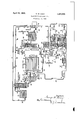
In order to more fully disclose the invention reference will now be had to the accompanying drawing which is a flow diagram of apparatus constructed in accordance with the invention, and constituting an embodiment thereof.
In the apparatus thus illustrated a pump serves to introduce'the charging stock, such as crude petroleum or other oil containing gasoline or naphtha constituents, through a charging line 11 into a heating coil 12. The Iatter coil isshown located in an economizer section or lower temperature portion of a furnace 13. The coil 12 -terminates in a transfer line 14 by which the heated oil is removed from the coil and discharged into a vaporizing chamber 15. Bafiles 16 are indicated in the chamber for assisting in the separation of the vapors from the liquid portions of the oil. The still 15 is provided with a fractionating or rectifying tower 17. A vapor line 18 conducts vapors from the still 15 to the fractionating tower 17 and a conducts liquid from the tower 17 back to the vaporizing chamber 15. In some cases the vaporizing or stripping chamber 15 and the introducted into a lower, and preferably a bafiled, section of a column still while fractionation of the vapors takes place in upper column; but it is often desirable to provide separate trated for the tionating vessel. A cooling coil 20 is shown for supplying cooling to the tower 17, and a vapor line 21 serves .to remove vapors from the tower and conduct them to a condenser 22 having an outlet pipe 23 by which the gasoline or naphtha fraction is discharged from the condenser. I
The stripped crude is removed from the still 15 and by means of a pipe 24 is conducted to a pump. 25 which forces the oil through a pipe 26 into a coil 27 located in the furnace 13. A burner 28 is indicated for supplying heat to the furnace, and the arrangement is such that the oil in transit through the coil 27 I'na be raised to a cracking temperature un er superatmospheric reflux condensate line 19 chambers as illusstripping still and the frach pressure. It is to be understood that the coil 12 is in a lower temperature section of the furnace 13 and does not receive the high temperature applied to the'coil 27. An auxiliary burner 29 is indicated for supplying additional heat to the coil 12 in case the waste gases that have'been employed in heating the coil 27 are inadequate for raising the temperture of the oil in the coil 12 to the desired egree. A transfer line 30 conducts the oil which has been heated to a cracking temperature in the coil 27 to a still or converted 31 wherein the oil is subjected to cracking or decomposition for the production of lower boiling point products. If desired a plurality or battery of stills or converters may be employed in lieu of the single still shown in the drawing. A vaporline 32 conducts evolved vapors from the still to a fractionating or rectifying tower 33. The tower is shown equipped with a coil 34 for supplying cooling thereto, and a vapor line 35 conducts the vapor fraction to a condenser coil 36" having an outlet pipe 37 communicating with a receiving drum 38. The receiving drum is preferably maintained under superatmospheric pressure, although the pressure in the drum may be reduced from that obtaining in the condenser 36. A'pipe 39 conducts the cracked gasoline or naphtha distillate to a tank 40. The condensate separated out in the-fractionating column 33 is conducted by a pipe 41'to a hot oil pump 42 which forces the hot condensate through a line 43 and thence into the coil 27, the line 43 preferably g with the coil 27 at a midpoint thereof so that the hot condensate may be combined with the charge introduced to the first part of the coil 27 at a temperature approximating the temperature of the charge with which it is combined.
The tar or residue 31 is removed by a pipe 44 to a vaporizing or expansion chamber 45 which operates at a pressure reduced from that obtaining in the still 31. The line 44 is provided with a pressure reducing valve 46 so that the pressure on the oil may be reduced in the c amber 45 preferably to substantially atmospheric pressure. The chamber 45 is preferably insulated to prevent loss of heat and does not ordinarily require any heating means other than the hot oil entering thereinto. The evolved vapors pass through a vapor line 47 to a fraetionating or rectifying column 48 from which the gasoline or naphtha fraction is taken off through a vapor line 49 to a condenser coil 50. An outlet pipe 51 conducts the gasoline or naphtha condensate to the tank 40. Th the tower 48 constitutes what may be termed a light gas oil fraction and is removed by a pipe 52 to a heat exchanger 53 having a coolingLcoil 54. The liquid is conducted by a line 55 to a cooling coil 56 from which the e liquid separated out in formed in "the cracking 1 maybe readily w1 cooled liquid delivered through a transfer line 57 to a tank 58.
Liquid or residue is drawn off from the vaporizing chamber '45 by a line 59 to a secondary distilling chamber 60. n It is convenient to have the va orizing chamber at a pressure slightly a ove atmospheric, say about ten pounds, so that the liquid residue drawn therefrom into the vaporizing chamber 60 which is held at substantiagiy atmospheric pressure. Live steam is intr uced into the chamber 60 by a pipe 61. The steam is preferably superheated and the gas oil fractions or other constituents which it is desired to distill off from the tar or residue, and which have not been vaporized in the chamber 45, are vaporized in the chamber 60. The vapors pass through a line 62 are combined with the strip tanks. The discharge -"-"e' t hl" thth connected 0 t 6 me 26 a t e g:- recelver 38 being under pressure, the distilwith the hot into a separator 63 provided with a cooling coil 64. Vapors-are taken off the separator by line 65 by which they are conducted to a condenser coil 66, and an outlet pipe 67 com ducts the condensate to the line 57 onto the tank 58. The liquid collected in the separator 63 may be said to constitute a heavy gas oil fraction. It is drawn off through a plpe 68 and passed through a cooling coil 69 from which an outlet pipe 70 conducts the liquid to a tank 72. The residue, which may be referred to as fuel oil, is drawn off from the vaporizing chamber 60 by a line 73 to a cooling coil 74 and passes thence into a fuel oil tank 75.
The gas oil distillates contained in the tanks 58 and 72 are cycled back to the cracking system for retreatm'ent for conversion into asoline and to accomplish thista pump 7 6 is provided having its inlet line'7 7 arranged with branch lines 78 and .7 9 communicating respectively with the tanks 58 and 72. The branch lines are valved so that the pump may draw oil from either of the tanks or it may draw a mixture consisting of oil from bot line 80 of the pump oil constituents which have been recovere from the residue from the cracking system tained from the vaporizing c amber 15 and the combined stripped crude and recovered gas oil wherein they are raised to' a cracking temrature. The line 77 is shown extendin to the line 52 and provided with a branch dine 87 connected to the line 68 so that the gas oil fractions may be drawn directly from the fractionating tower 48 and the separator 63 and introduced into the coil 27 in a heated condition. Thus condensate may from either or both of the separators 48 and 63 at temperatures not substantially below its boiling point and the hot oil combined liquid obtained in the crude d charge obdistillates are forced into the pipe 27 be withdrawn stripping apparatus for passage directly into the coil 27.
The pipe 23 which receives the gasoline or naphtha distillate obtained from the crude stripping apparatus, or in other words, the natural gasoline content of the crude charge, is shown extending to the tank 40 so that the natural gasoline may be combined with the cracked gasoline obtained from the crackin system and the'cracked gasoline recovered from the tar stripping operation, but if, desired these distillates may be received in separate tanks. In some cases it is advantaeous to form several cuts or fractions from e vapors'from the stripping still 15. Thus a gas line and a kerosene cut may be made in ad "tion to the gas oil cut.
,As stated the fractionating tower. 33 is equipped with a cooling coil 34 but if desired in lieu of this coil or in addition thereto distillate may be drawn from the receiving drum 38 or from the condenser coil 36 and admitted to the tower or serve as areflux medium. Thus a pump 81 is provided havin a discharge line 82 entering the top of' the fractionating tower 33. The inlet line 83 of the pump communicates with a line 84 which has a branch line 85 connected to the line 37, preferably at a point therein before the pressure has been reduced by the valve indicated in this line, and the line 85 has another branch line 86 extending to. the pipe 39, so that distillate may thus be drawn either directly from the condenser outlet 36 or from the outlet of the receiving drum 38 and introduced into tower 33 as a reflux medium. r
The line 84 is shown extending to the tower 17 so that if desired the distillate drawn 01? either fromthe condenser 36 or from the relates from the condenser coil or receiving drum are thereby forced under pressure into I the tower 17 The cooling medium supplied to the coils 20, 34, 54 and 64 ma consist of water or other extraneous fluid but I prefer to employ the oil charge or some of the distillates obtained-in the. process to serve as the cooling medium in these several coils. Thus naphtha or gasoline condensate may be pumped from the tank 40 through the coil 20, or may be drawn off from either the condenser coil 36 .or the receiving drum 38 and passed into the coil 20. "If desired the oil after passing through the coil 20 may be discharged into the tower 17 at a point therein below the coil 20. If desired the crude charge or a portion thereof may be passed through the coil20.
, tanks after having been cooled 'coils 54 and 64.
single still in utilized in vaporizing branch lines extending to the coil 20 with a valve in the line 11 intermediate the point of juncture of the two lines extending to the coil 20, so that-the crude charge on its Way to the heating coil 12 may thusbe preheated by passage through the coil 20 and thereby supply the required cooling to the tower 17. If desired the line 11 may be similarly connectedto the coil 34 so that crude charge may be used as a cooling medium in the top of the pressure fractionating tower 33. On the other hand, when the cycle gas oil fractions obtained from the tar stripping operation are introduced intoithepressure system down, as when being drawn off from either or both of the 58 and 72, the gas oil constitutes a good medium to be employed as a cooling agent in the top of the tower 33 and thus the line 80 may be provided with valved branch lines extending to the coil 34 and with a valve in the line 80 intermediate the point of juncture of the lines extending to the coil 34.
It is preferable to use the crude charging stock as the cooling agent in the coils 54 and 64. Thus the coils 54 and 64 may be "con-- nected in series and branch lines installed connecting the line 11 with the coils 54 and 64 and with a valve in the line 11 intermediate the point of juncture of the branch lines so that the crude charge may thus be introduced into the coil 54 passed thence into the coil 64' and then returned to the charging line 11 and introduced into the heating coil 12. v
. A preferred arrangement is to employ distillate from either the condenser 36 or the receiver 38 or the tank 40 as a cooling medium in the coil 20, to employ cycle charge to the cracking system as obtained from line 80 as the cooling medium for the coil 34 and to employ the crude oil charge as introduced to the line 11- as the cooling medium in the If desired instead of having the two distilling chambers 45 and the entire residue stripping operation may be carried on in a which the contained heatof thehot residue together with such additional heating, such as steam, as may be required, is the residue. In such an operation the vapors from the stripping stillpass to a dephlegmator or fractionating a column from which an overhead fIflCtlOIPlS conducted to a condenser and the resultant naphtha or gasoline condensate conducted to storage. The liquid condensate obtained from the dephlegmator or rectifying tower may be drawn off and cycled back to the pressure cracking system.
What I claim is:
Apparatus for treating hydrocarbon oils comprising a high pressure heating coil, a furnace in which the coil is mounted and which is adapted to heat the oil to a cracking temperature,
a cracking still into which the coil discharges, a dephlegmator arranged to receive vapors from the cracking still, means for conducting reflux condensate from the dephlegmator to the high pressure heating coil, a lower temperature heating coil mounted in an economizer section of the furnace so that it may be heated by Waste gases employed in heating the high, temperature coil, means for introducing charging stock into the low temperature heating coil, a vaporizing chamber into which said coil discharges, means for removing liquid from the vaporizing chamber and introducing it into the high temperature heating coil, a residual oil vaporizing chamber, means for conducting residue from the cracking still to the residual oil vaporizing chamber and means associated therewith for reducing pressure in the residual oil vaporizing chamber, means for drawing ofi vapors from said vaporizing chamber and obtaining a condensate therefrom, and means for conducting the condensate to the high pressure heating coil.
In witness whereof I have hereunto set my hand this 27th day of January, 1928.
- GEORGE W. GRAY.
Priority Applications (1)
| Application Number | Priority Date | Filing Date | Title |
|---|---|---|---|
| US252071A US1854835A (en) | 1928-02-06 | 1928-02-06 | Treating hydrocarbon oils |
Applications Claiming Priority (1)
| Application Number | Priority Date | Filing Date | Title |
|---|---|---|---|
| US252071A US1854835A (en) | 1928-02-06 | 1928-02-06 | Treating hydrocarbon oils |
Publications (1)
| Publication Number | Publication Date |
|---|---|
| US1854835A true US1854835A (en) | 1932-04-19 |
Family
ID=22954468
Family Applications (1)
| Application Number | Title | Priority Date | Filing Date |
|---|---|---|---|
| US252071A Expired - Lifetime US1854835A (en) | 1928-02-06 | 1928-02-06 | Treating hydrocarbon oils |
Country Status (1)
| Country | Link |
|---|---|
| US (1) | US1854835A (en) |
-
1928
- 1928-02-06 US US252071A patent/US1854835A/en not_active Expired - Lifetime
Similar Documents
| Publication | Publication Date | Title |
|---|---|---|
| US1854835A (en) | Treating hydrocarbon oils | |
| US1895081A (en) | Method for converting hydrocarbon materials | |
| US2073456A (en) | Method for treating crude oil | |
| US2198557A (en) | Cracking hydrocarbon oils | |
| US2023619A (en) | Treating hydrocarbon oils | |
| US2036968A (en) | Treatment of hydrocarbon oils | |
| US2142075A (en) | Conversion of hydrocarbon oil | |
| US2224570A (en) | Treatment of hydrocarbon oils | |
| US2246607A (en) | Conversion of hydrocarbon oils | |
| US2406312A (en) | Cracking and coking of hydrocarbon oils | |
| US2126204A (en) | Conversion of hydrocarbon oils | |
| US1933048A (en) | Cracking process | |
| US2102234A (en) | Distillation of oil | |
| US2219521A (en) | Conversion of hydrocarbon oils | |
| US1781884A (en) | Art of cracking hydrocarbons | |
| US1958959A (en) | Treating hydrocarbon oils | |
| US2094907A (en) | Treatment of hydrocarbon oils | |
| US1931757A (en) | Process for cracking hydrocarbon oils | |
| US1950058A (en) | Treating hydrocarbon oils | |
| US2276249A (en) | Conversion of hydrocarbon oils | |
| US2081348A (en) | Conversion of hydrocarbon oils | |
| US1923271A (en) | Process and apparatus for fractionating petroleum | |
| US2109631A (en) | Conversion of hydrocarbon oils | |
| US2127013A (en) | Conversion of hydrocarbon oils | |
| US1965074A (en) | Treating hydrocarbon oils |