US1854815A - Culvert - Google Patents
Culvert Download PDFInfo
- Publication number
- US1854815A US1854815A US544232A US54423231A US1854815A US 1854815 A US1854815 A US 1854815A US 544232 A US544232 A US 544232A US 54423231 A US54423231 A US 54423231A US 1854815 A US1854815 A US 1854815A
- Authority
- US
- United States
- Prior art keywords
- culvert
- units
- timbers
- unit
- rods
- Prior art date
- Legal status (The legal status is an assumption and is not a legal conclusion. Google has not performed a legal analysis and makes no representation as to the accuracy of the status listed.)
- Expired - Lifetime
Links
- 238000010276 construction Methods 0.000 description 7
- WHRZCXAVMTUTDD-UHFFFAOYSA-N 1h-furo[2,3-d]pyrimidin-2-one Chemical compound N1C(=O)N=C2OC=CC2=C1 WHRZCXAVMTUTDD-UHFFFAOYSA-N 0.000 description 2
- 235000006173 Larrea tridentata Nutrition 0.000 description 2
- 244000073231 Larrea tridentata Species 0.000 description 2
- 229960002126 creosote Drugs 0.000 description 2
- 239000007788 liquid Substances 0.000 description 2
- 101000916225 Schizosaccharomyces pombe (strain 972 / ATCC 24843) Cullin-4 Proteins 0.000 description 1
- 238000012512 characterization method Methods 0.000 description 1
- 239000011248 coating agent Substances 0.000 description 1
- 238000000576 coating method Methods 0.000 description 1
- 230000000295 complement effect Effects 0.000 description 1
- 239000000470 constituent Substances 0.000 description 1
- 239000003755 preservative agent Substances 0.000 description 1
- 238000007665 sagging Methods 0.000 description 1
- 239000007787 solid Substances 0.000 description 1
- 239000000126 substance Substances 0.000 description 1
- XLYOFNOQVPJJNP-UHFFFAOYSA-N water Substances O XLYOFNOQVPJJNP-UHFFFAOYSA-N 0.000 description 1
- 239000003171 wood protecting agent Substances 0.000 description 1
Images
Classifications
-
- F—MECHANICAL ENGINEERING; LIGHTING; HEATING; WEAPONS; BLASTING
- F16—ENGINEERING ELEMENTS AND UNITS; GENERAL MEASURES FOR PRODUCING AND MAINTAINING EFFECTIVE FUNCTIONING OF MACHINES OR INSTALLATIONS; THERMAL INSULATION IN GENERAL
- F16L—PIPES; JOINTS OR FITTINGS FOR PIPES; SUPPORTS FOR PIPES, CABLES OR PROTECTIVE TUBING; MEANS FOR THERMAL INSULATION IN GENERAL
- F16L9/00—Rigid pipes
- F16L9/01—Rigid pipes of wood
Definitions
- This invention relates to culvert construction and the object of the invention is to produce a culvert construction of exceptional strength particularly adapted for'use inlcul-
- the invention relates generally to the same general class of structure as disclosed in my Patent No. 1,403,063, issued January 10, 1922, but dilfers from the construction of that vert of my prior invention was composed of units of a plurality of plies in thickness whereas the culvert of the present invention is built up from a plurality of units each of which is, in the direction of its thickness, composed of a single ply.V
- the object of the invention is to provide a culvert of great strength which may be made of scrap timber.
- the ordinary scrap has been found to give viding the great strength which isrequired in some culvert constructions.
- the present invention is characterizedby the fact that the timbers which go to make up the respective units of the culvert, instead of being laid flat with respect to the face of the unit, are set on edge so that their greatest crosssectional dimensions are in the direction of the thickness of the unit. For example, if designed requires for the necessary strength a 6 make up the culvert are or lumber 6 wide and appropriate thickness such as two or four inches as may be convenient.
- the culvert of this invention is made up of a plurality of units of this character.
- the structure of this invention Vpermits me to ship units in knockdown form to the place where they are to be assembled and they lmay thus be set up and united to form a finished culvert of great strength, rigidity, and durability.
- the lumber entering into the construction may be treated with preservatlves against boring inseots or decay and such preservatives mayconveniently be creos'ote or any other similar Substance.
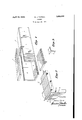
- Figure l is a perspective view of a portion of a culvertembodying the present invention. In this view two of the units are shown as removed from thecul-y vert to more clearly illustrate the manner in which the various units are assembled to form a complete structure. I
- Figure 2' is a perspective view showing'on somewhat enlarged scale the manner in which two of the culvert sections are fabricated and joined together.
- FIG. 3 shows an employ to secure the angle bar which I may units formingi the top as'desired. It will of course be apparent,
- all of the units of any of the four sides of the culvert should be of the same width but they may vary in length; It is desirable, however, that they be assembled in the manner shown so that the joints between the units of the top and bottom of the joints between bers in face abutting relation.
- culvert will be staggered with respect to the the units at the sides "of the culvert. This will give longitudinal strength Vto the culvert and will preclude sagging.
- All of the units are preferably individually fabricated in the same manner and in Figure 2 I have shown how they are built up.
- Each unit is made by arranging on edge a succession of boards, planks or timbers' 4 so that their edges preferably lie in the same plane with the faces of the consecutive timi The timbers are arranged in succession in the manner stated until the unit of the desired length has been obtained and then tie bolts or truss rods 5 are passed'through registering holes in the consecutive timbers after the manner shown in Figure 2 and these rods are of such length as to eXtend from one end of the unit to the other.
- each rod may be headed while the other end of each rod is preferably threaded to receive the end 6 which when screwed upon the rod eXerts sufficient tension on said rods to draw all of the timbers 4 into close intimate contact and bind them firmly together.
- the holes in the several timbers through which the rods 5 extend may be bored before assembly through the use of an appropriate templet orjig 'but if desired the timbers may first be assemble and the boring operation carried on for the entire length of the units.
- the terminal timbers of the units are preferably provided at their outer faces with recesses in the region of the holes which receive the rods and the heads and ends of the rods are received'in these recesses so that the ends o the units are flush.
- Threaded boltsl with nuts as described are preferably used to bind the timbers of the units together but the rods may be headed over at both ends if desired.
- Wood preservative such as creosote may be employed to advantage and timbersmay be creosoted either before or after assembly. In any event when these timbers are wholly drawn together Vwith a coating of creosote they provide. an absolutely liquid and air tight wall of great strength, the actual strigbled at the factory place of use there to be joined together to' strength of which depends upon the width of the timbers employed.
- tie rods 5 may be positioned in any suitable' place with respect to the thickness or width of the individual unit in which they are incorporated but I have found that three rods are entirely satisfactory for the majority of culverts and that these rods are best disposed' as shown in Figure 2 of the drawings wherein I have illustrated two rods adjacent the lateral edges of the unit and also adjaeent one face of the unit with the third rod positioned substantially midway of the the. unit and adj aeent the opposite face. This arrangement will effectually keep the timbers from warping and preclude the opening of the joints between consecutive timbers at any point or adjacent either face.
- the'units may be individually fabricated either at the place where they are to be ultimately used or they may be asand Shipped to the form the culvert.
- the timbers which make up the unit are cut to length at the factory and if they are to be joined at their ends this operation is also carried out at the same time so that there will be no actual carpenter work necessary on the job. This minimizes expense and expedites the actual building of the culvert.
- the units may be made to cooperate at their lateral edges with the contiguous edges of other units to form the four walls of the culvert of rectangular characterization and in the acc-ompanying drawings the units are provided at the edges with stepped joints. This is a Very satisfactory joint as it perthe culvert, i. e. the
- width of llO '35 culvert may be mits the units to be readily lined up in building the culvert.
- exampleI may use the angle bars such as illustrated in Figure 3 which angle bars after being placed over the edges of the culvert are secured to the walls which they overlap by means of spikes to bind the parts together.
- the units are staggered so as to break joints as shown in Figure 1 it is not necessary to actually secure to one another the consecutive units of any particular wall of the culvert, for obvious reasons, but they may be secured together by bolts or in any other suitable manner without departing from this invention.
- the culvert of this invention embodies many marked practical advantages.
- Men at the job may, without the use of derricks, lifts or other machinery necessary to handle great weights, pick up these easily handled weights and place them in the position which they are to occupy in a suflicient number, for example, to constitute one unit and the tie rods may then be drawn through the holes of the timbers of this unit and the nuts applied to bind the timbers together, and the unit which could not possibly be handled without the use of weight lifting machinery, is readily installed and yet no such machinery is necessary under the practice as I have outlined it. N evertheless, the resulting unit will be of great strength and thoroughly eflicient for its intended purposes.
- a culvert embodying a plurality of units each of which units is fabricated from pieces of lumber stood on edgeand extending transversely of the culvert with the longitudinal edges of said pieces of lumber forming inner and outer surfaces of the culvert and the faces of the consecutive pieces in face abutting relation, tie rods eXtending through the pieces of lumber of each particular unit from end to end of said unit in a direction longitudinal of the culvert and serving to bind all the pieces of lumber of each particular unit firmly together to form the unit, and additional means acting upon the several units independently of the tie rods for securing the several units to one another to form the culvert.
Landscapes
- Engineering & Computer Science (AREA)
- General Engineering & Computer Science (AREA)
- Life Sciences & Earth Sciences (AREA)
- Wood Science & Technology (AREA)
- Mechanical Engineering (AREA)
- Sewage (AREA)
Description
verts of large size.
' the culvert to be Patented Apr. 19, 1932 UNITED STATES WILLIAM J. TUR/NER, OF
KANSAS CITY, MISSOURI CUL-VERT Aypncafion fiiea June 13,
This inventionrelates to culvert construction and the object of the invention is to produce a culvert construction of exceptional strength particularly adapted for'use inlcul- The invention relates generally to the same general class of structure as disclosed in my Patent No. 1,403,063, issued January 10, 1922, but dilfers from the construction of that vert of my prior invention was composed of units of a plurality of plies in thickness whereas the culvert of the present invention is built up from a plurality of units each of which is, in the direction of its thickness, composed of a single ply.V
Speaking generally, the object of the invention is to provide a culvert of great strength which may be made of scrap timber. As no great lengths are required ordinarily, the ordinary scrap has been found to give viding the great strength which isrequired in some culvert constructions. The present invention is characterizedby the fact that the timbers which go to make up the respective units of the culvert, instead of being laid flat with respect to the face of the unit, are set on edge so that their greatest crosssectional dimensions are in the direction of the thickness of the unit. For example, if designed requires for the necessary strength a 6 make up the culvert are or lumber 6 wide and appropriate thickness such as two or four inches as may be convenient. These various timbers lare placed on edge in face abutt'ing relation and are securely bound together to form one of the units of the culvert by bolts or tie rods. These tie rods are associated with the units by boring holes from one end to the other through the units, by then passing the tie rods through these holes in Ithe consecutive planks and bolting the planks firmly together or heading over the end of the tie rods, as by riveting or in any other suitable way. The advantage of this construction is that the respective planks in any particular unit. are firmly'and positively bound together by the tension member which extends for composed of planks patent in that the cul-4 very satisfactory results while prowall, the units which they maybe of any 1931. SeraI No. 544,232.
the full length of the unit and my experience has shown that no matter how heavy the individual planks may be and no matter how large the units may individually be constructed said units will maintain their shape and form; They will no-t warp, bend or become distorted and will stand tremendous external as well as internal pressures.
The culvert of this invention is made up of a plurality of units of this character.
hat is to say, four walls of the culvert of rectangular cross-section are each composed of a succession of these units placed end to end and securedtoone another and laterally adjacent units of the other walls in any appropriate Vmanner.
The structure of this invention Vpermits me to ship units in knockdown form to the place where they are to be assembled and they lmay thus be set up and united to form a finished culvert of great strength, rigidity, and durability. The lumber entering into the construction may be treated with preservatlves against boring inseots or decay and such preservatives mayconveniently be creos'ote or any other similar Substance. i
'Features of the invention, other than those specified, will be apparent from the hereinafter detailed description and claims, when read iniconjunction with the accompanying drawings. i i
In the accompanying drawings, I have illustrated onepractical form of the invention but the showing herein made' is to be understood as illustrative only and Inot as defining the limits'of the invention.
In the drawings, Figure l is a perspective view of a portion of a culvertembodying the present invention. In this view two of the units are shown as removed from thecul-y vert to more clearly illustrate the manner in which the various units are assembled to form a complete structure. I
Figure 2' is a perspective view showing'on somewhat enlarged scale the manner in which two of the culvert sections are fabricated and joined together.
Figure 3 shows an employ to secure the angle bar which I may units formingi the top as'desired. It will of course be apparent,
however, that all of the units of any of the four sides of the culvert should be of the same width but they may vary in length; It is desirable, however, that they be assembled in the manner shown so that the joints between the units of the top and bottom of the joints between bers in face abutting relation.
culvert will be staggered with respect to the the units at the sides "of the culvert. This will give longitudinal strength Vto the culvert and will preclude sagging.
All of the units are preferably individually fabricated in the same manner and in Figure 2 I have shown how they are built up. Each unit is made by arranging on edge a succession of boards, planks or timbers' 4 so that their edges preferably lie in the same plane with the faces of the consecutive timi The timbers are arranged in succession in the manner stated until the unit of the desired length has been obtained and then tie bolts or truss rods 5 are passed'through registering holes in the consecutive timbers after the manner shown in Figure 2 and these rods are of such length as to eXtend from one end of the unit to the other. One end of each rod may be headed while the other end of each rod is preferably threaded to receive the end 6 which when screwed upon the rod eXerts sufficient tension on said rods to draw all of the timbers 4 into close intimate contact and bind them firmly together. The holes in the several timbers through which the rods 5 extend may be bored before assembly through the use of an appropriate templet orjig 'but if desired the timbers may first be assemble and the boring operation carried on for the entire length of the units. Furthermore the terminal timbers of the units are preferably provided at their outer faces with recesses in the region of the holes which receive the rods and the heads and ends of the rods are received'in these recesses so that the ends o the units are flush. Threaded boltsl with nuts as described are preferably used to bind the timbers of the units together but the rods may be headed over at both ends if desired. Wood preservative such as creosote may be employed to advantage and timbersmay be creosoted either before or after assembly. In any event when these timbers are wholly drawn together Vwith a coating of creosote they provide. an absolutely liquid and air tight wall of great strength, the actual seinbled at the factory place of use there to be joined together to' strength of which depends upon the width of the timbers employed. For various culvert constructions I have used in the past timbers Qi, X sll, 2,/ X ll, 21/ X 5,/7 2/1 X 61, according to the width of transverse span of the wall of which the unit is to form a part although it is entirely feasible to use thicker and wider timbers where the circumstances require greater strength. The particular dimensions given are those which I have mainly used and are for the purpose of illustration only. I do not bind myself to exact dimensions, the invention beingV directed in this connection to the setting of the timbers on edge and in face abutting relation to form the culvert walls, and being further directed to the use of tension bars such as tie rods extending the full length ofthe units and binding the various timbers firmly together.
If such a unit is built of ordinary lumber and is subsequently Operating in the ground or used to convey liquids, the moisture which will invariably work into the lumber would tend to slightly increase the thickness of the individual timbers and in so doing will make the joints even tighter than they were.
In carrying out this invention I may use any desired number of tie rods 5 as described and they may be positioned in any suitable' place with respect to the thickness or width of the individual unit in which they are incorporated but I have found that three rods are entirely satisfactory for the majority of culverts and that these rods are best disposed' as shown in Figure 2 of the drawings wherein I have illustrated two rods adjacent the lateral edges of the unit and also adjaeent one face of the unit with the third rod positioned substantially midway of the the. unit and adj aeent the opposite face. This arrangement will effectually keep the timbers from warping and preclude the opening of the joints between consecutive timbers at any point or adjacent either face. In'practice the'units may be individually fabricated either at the place where they are to be ultimately used or they may be asand Shipped to the form the culvert. In any event the timbers which make up the unit are cut to length at the factory and if they are to be joined at their ends this operation is also carried out at the same time so that there will be no actual carpenter work necessary on the job. This minimizes expense and expedites the actual building of the culvert.
The units may be made to cooperate at their lateral edges with the contiguous edges of other units to form the four walls of the culvert of rectangular characterization and in the acc-ompanying drawings the units are provided at the edges with stepped joints. This is a Very satisfactory joint as it perthe culvert, i. e. the
width of llO '35 culvert may be mits the units to be readily lined up in building the culvert. I am of course aware that other forms of joints such as a mitred joint may be employed and I do not limit the invention to the particular type of joint shown.
f course, the units which form the top, bottom and side walls of the culvert must be secured together. This may be accomplished as shown in my prior patent hereinbefore referred to or in any other suitable way.
or eXampleI may use the angle bars such as illustrated in Figure 3 which angle bars after being placed over the edges of the culvert are secured to the walls which they overlap by means of spikes to bind the parts together. VVhen the units are staggered so as to break joints as shown in Figure 1 it is not necessary to actually secure to one another the consecutive units of any particular wall of the culvert, for obvious reasons, but they may be secured together by bolts or in any other suitable manner without departing from this invention. The culvert of this invention embodies many marked practical advantages. For example, if a culvert of great strength is required to be built in some out of the way place it is entirely practical according to this invention to cut to size and shape the timbers which will necessarily be incorporated into each unit and to ship these timbers jointed and bored for the tie rods, in knockdown creosoted condition in a box car or by truck directly to the job, with an appropriate number of tie r-ods to bind the constituent parts of the several necessary units together. Men at the job may, without the use of derricks, lifts or other machinery necessary to handle great weights, pick up these easily handled weights and place them in the position which they are to occupy in a suflicient number, for example, to constitute one unit and the tie rods may then be drawn through the holes of the timbers of this unit and the nuts applied to bind the timbers together, and the unit which could not possibly be handled without the use of weight lifting machinery, is readily installed and yet no such machinery is necessary under the practice as I have outlined it. N evertheless, the resulting unit will be of great strength and thoroughly eflicient for its intended purposes. On the -other hand on j obs where derricks or hoists may be used with convenience the units may be completed at the factory and shipped in this condition on flat cars or otherwise to the job there to be picked up by derricks and lifted into place to complete the culvert. It will thus be apparent that I can employ the present invention in a manner thoroughly practical for any type of job and in either small or large building operations in a thoroughly convenient and practical way. I wish it also understood that the joints between the several units of the covered, calked or otherwise rendered Water tight to preclude leakage or seepage without departing from this invention.
The foregoing detailed description sets forth the invention in its preferred practical form, but the invention is to be understood as fully commensurate with the appended claims.
Having thus fully described my invention, what I claim as new and desire to secure by Letters Patent is:
1. A culvert embodying a plurality of units, each of which units is fabricated from pieces of lumber stood on edgeand extending transversely of the culvert with the longitudinal edges of said pieces of lumber forming inner and outer surfaces of the culvert and the faces of the consecutive pieces in face abutting relation, tie rods eXtending through the pieces of lumber of each particular unit from end to end of said unit in a direction longitudinal of the culvert and serving to bind all the pieces of lumber of each particular unit firmly together to form the unit, and additional means acting upon the several units independently of the tie rods for securing the several units to one another to form the culvert.
2. A culvert embodying a plurality of units each of which is individually built and may be handled separately, each unit comprising pieces of lumber set on edge with the faces of consecutive pieces in face abutting relation and with solid tie rods extending through all the pieces of each individual unit to secure said pieces to one another, each piece of lumber being jointed at its opposite ends to cooperate with complementary joints in the lumber of the laterally adjacent units of the culvert, and means, separate and independent of said tie rods, for fastening the several units together to form a finished culvert, the joints between the consecutive units of the top, bottom and side walls of the culvert breaking joints with respect to one another to render the culvert longitudinally rigid.
In testimony whercof, I have signed the foregoing specification.
WILLIAM J. TURNER.
Priority Applications (1)
| Application Number | Priority Date | Filing Date | Title |
|---|---|---|---|
| US544232A US1854815A (en) | 1931-06-13 | 1931-06-13 | Culvert |
Applications Claiming Priority (1)
| Application Number | Priority Date | Filing Date | Title |
|---|---|---|---|
| US544232A US1854815A (en) | 1931-06-13 | 1931-06-13 | Culvert |
Publications (1)
| Publication Number | Publication Date |
|---|---|
| US1854815A true US1854815A (en) | 1932-04-19 |
Family
ID=24171322
Family Applications (1)
| Application Number | Title | Priority Date | Filing Date |
|---|---|---|---|
| US544232A Expired - Lifetime US1854815A (en) | 1931-06-13 | 1931-06-13 | Culvert |
Country Status (1)
| Country | Link |
|---|---|
| US (1) | US1854815A (en) |
Cited By (8)
| Publication number | Priority date | Publication date | Assignee | Title |
|---|---|---|---|---|
| US2657713A (en) * | 1943-05-08 | 1953-11-03 | Wheeler Lumber Bridge And Supp | Wood culvert having laminated wall sections |
| US4983070A (en) * | 1988-11-21 | 1991-01-08 | Hwang Hyun Ho | Prefabricated culvert system |
| US6107565A (en) * | 1998-11-17 | 2000-08-22 | A&A Manufacturing Co., Inc. | Covered energy transmission line carrier |
| US7530764B1 (en) | 2007-12-11 | 2009-05-12 | Joe Gallegos | Easy clean culvert system |
| RU2588251C2 (en) * | 2014-07-07 | 2016-06-27 | Федеральное государственное бюджетное учреждение "3 Центральный научно-исследовательский институт" Министерства обороны Российской Федерации | Rectangular water inlet tube from srdp plate |
| US20180050467A1 (en) * | 2016-08-22 | 2018-02-22 | LowSpan LLC | Pre-Stressed Box Culvert and Methods for Assembly Thereof |
| US11059201B2 (en) * | 2016-08-22 | 2021-07-13 | LowSpan LLC | Pre-stressed box culvert and methods for assembly thereof |
| US20230235519A1 (en) * | 2021-05-21 | 2023-07-27 | Alexander B. Schorstein | Storm water and traffic collector box culvert |
-
1931
- 1931-06-13 US US544232A patent/US1854815A/en not_active Expired - Lifetime
Cited By (9)
| Publication number | Priority date | Publication date | Assignee | Title |
|---|---|---|---|---|
| US2657713A (en) * | 1943-05-08 | 1953-11-03 | Wheeler Lumber Bridge And Supp | Wood culvert having laminated wall sections |
| US4983070A (en) * | 1988-11-21 | 1991-01-08 | Hwang Hyun Ho | Prefabricated culvert system |
| US6107565A (en) * | 1998-11-17 | 2000-08-22 | A&A Manufacturing Co., Inc. | Covered energy transmission line carrier |
| US7530764B1 (en) | 2007-12-11 | 2009-05-12 | Joe Gallegos | Easy clean culvert system |
| RU2588251C2 (en) * | 2014-07-07 | 2016-06-27 | Федеральное государственное бюджетное учреждение "3 Центральный научно-исследовательский институт" Министерства обороны Российской Федерации | Rectangular water inlet tube from srdp plate |
| US20180050467A1 (en) * | 2016-08-22 | 2018-02-22 | LowSpan LLC | Pre-Stressed Box Culvert and Methods for Assembly Thereof |
| US10518440B2 (en) * | 2016-08-22 | 2019-12-31 | LowSpan LLC | Pre-stressed box culvert and methods for assembly thereof |
| US11059201B2 (en) * | 2016-08-22 | 2021-07-13 | LowSpan LLC | Pre-stressed box culvert and methods for assembly thereof |
| US20230235519A1 (en) * | 2021-05-21 | 2023-07-27 | Alexander B. Schorstein | Storm water and traffic collector box culvert |
Similar Documents
| Publication | Publication Date | Title |
|---|---|---|
| US1377891A (en) | Wooden beam | |
| DE1534692C3 (en) | Multi-layer wall | |
| US2107427A (en) | Mold for concrete walls or the like | |
| US1854815A (en) | Culvert | |
| US2177277A (en) | Metal stud | |
| US2287370A (en) | Roof framing support | |
| US2118048A (en) | Laminated structure | |
| US2099542A (en) | Interlocking steel sheet piling | |
| US2245688A (en) | Roof structure | |
| US1724284A (en) | Building construction | |
| US1533960A (en) | Form for concrete construction | |
| US2288193A (en) | Structural member and building structure | |
| US2607959A (en) | Flange beams of wood | |
| US2002506A (en) | Truss structure | |
| US1089010A (en) | Combination wood and concrete silo. | |
| GB540881A (en) | Improvements in or relating to buildings or structures | |
| US1930988A (en) | Field box head | |
| US1733923A (en) | Continuous grating structure | |
| US1973882A (en) | Roof truss | |
| DE886062C (en) | Lattice girder made of wood | |
| US2841977A (en) | Welding and assembling floor | |
| GB402162A (en) | Improvements in and relating to joints for packing cases and other structures | |
| US2980216A (en) | Constructional metalwork | |
| US1093904A (en) | Silo. | |
| US3113648A (en) | Metallic building structures |