US1854814A - Device for filling fountain pens - Google Patents
Device for filling fountain pens Download PDFInfo
- Publication number
- US1854814A US1854814A US454232A US45423230A US1854814A US 1854814 A US1854814 A US 1854814A US 454232 A US454232 A US 454232A US 45423230 A US45423230 A US 45423230A US 1854814 A US1854814 A US 1854814A
- Authority
- US
- United States
- Prior art keywords
- ink
- piston
- chamber
- pen
- stem
- Prior art date
- Legal status (The legal status is an assumption and is not a legal conclusion. Google has not performed a legal analysis and makes no representation as to the accuracy of the status listed.)
- Expired - Lifetime
Links
- 239000007788 liquid Substances 0.000 description 21
- 238000007789 sealing Methods 0.000 description 5
- 239000000470 constituent Substances 0.000 description 2
- 238000010276 construction Methods 0.000 description 2
- 230000008020 evaporation Effects 0.000 description 2
- 238000001704 evaporation Methods 0.000 description 2
- 238000003780 insertion Methods 0.000 description 2
- 230000037431 insertion Effects 0.000 description 2
- 239000000463 material Substances 0.000 description 2
- 229920001875 Ebonite Polymers 0.000 description 1
- ISWSIDIOOBJBQZ-UHFFFAOYSA-N Phenol Chemical compound OC1=CC=CC=C1 ISWSIDIOOBJBQZ-UHFFFAOYSA-N 0.000 description 1
- 238000004140 cleaning Methods 0.000 description 1
- 238000004891 communication Methods 0.000 description 1
- 239000007859 condensation product Substances 0.000 description 1
- 238000006073 displacement reaction Methods 0.000 description 1
- 238000012986 modification Methods 0.000 description 1
- 230000004048 modification Effects 0.000 description 1
- 210000003899 penis Anatomy 0.000 description 1
Images
Classifications
-
- B—PERFORMING OPERATIONS; TRANSPORTING
- B43—WRITING OR DRAWING IMPLEMENTS; BUREAU ACCESSORIES
- B43L—ARTICLES FOR WRITING OR DRAWING UPON; WRITING OR DRAWING AIDS; ACCESSORIES FOR WRITING OR DRAWING
- B43L25/00—Ink receptacles
- B43L25/02—Ink receptacles with separate dipping-cups
- B43L25/04—Ink receptacles with separate dipping-cups supplied by pressure arrangements
Definitions
- 'My'invention relates generally to fountain pen filling devices and more particularly to automatic means incorporated in anink well whereby a fountain pen may easily be refilled without the necessity 'of operating the usual filling means provided in the pen. It is among the objects of my invention to provide an improvedcombination ink well and filling device: (1) which will operate automatically upon insertion of afountain pen to fill or partially fill the barrel or reservoir thereof; (2) which will operate automatically upon insertion of a fountain pen to create a partial vacuum within the reservoir of the pen; (3) in which the partial vacuum created in the reservoir of the penis relieved near the completion of the operating stroke; (4:) by which-a fountain pen may be filled without permitting any except the end surface of the pen section or barrel to come in contact with the ink (5) which is operable by a single stroke, first, to exhaust air from the fountain pen reservoir and then permit filling the said reservoir by the in-flow of ink under atmospheric pressure; (6) in which an improved means for forming a seal with the end of the pen section or barrel is
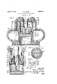
- Fig. 4 is a fragmentary elevational view showing the check valve construction.
- the device of my invention comprises a body 10 made of hard rubber, phenol condensation products, or any similar material, which may easily be formed to the desired shape and which will not be corroded by the usual constituents of ink.
- the body has an axial cylinder bore 12 formed in the lower end thereof and a similar bore 14 formed in the upper end thereof.
- the wall 16 between the ends of these bores has a central opening 18 and forms a guide for a stem 20, which is preferably formed integrally with a piston 22 reciprocable in the cylinder 12.
- the upper end of the stem 20 is tubular in shape so as to be adapted to receive a soft rubber obturator tube 24 which is shouldered at 26 to fit over the end of the stem 20 and is held in place by a ring 28 threaded over the end of the stem and slidably fitting in the cylindrical bore 14.
- the upper end of the obturator tube has a frusto-conical seating surface /30 which is adapted to engage and seal against the outer lower edge of the section or barrel of a fountain pen, as indicated in Fig. 2.
- the obturator tube is thus adapted to make an air tight connection with fountain pens having the ends of their sections of different diam eters.
- a conical coil spring 32 has its lower end seated upont-he cross-wall 16 and its upper end engaging beneath the ring 28.
- the stem 20 has a vertical passageway 34 communicating with the interior of the obturator tube 24, the lower end of the passageway 34 being connected to one or more substantially horizontal ducts 36.
- the body 10, together with the parts mounted therein, may be inserted in any suitable ink well orcontainer 38, the body having an enlarged diameter portion 40 fitting within a eomplementally shaped opening 46 in the ink well and having an outwardly extending head 48 to limit the depth to which the body may be inserted in the ink well.
- the body has one or more diagonal passageways 50 which are adapted to permit escape of air from the interior of the ink well upon depression of the stem, the upper end 1 bore 14 so that should any ink accidentally collect within this bore it will be. ejected through the passageway 52 into the ink well upon downward movement of the ring 28 which thus acts as a piston.
- a plurality of radial ducts 58 are provided in the body 10 at the upper end of the cylindrical bore 12, the outer ends of these ducts being normally closed by flap check valves 60.
- these check valves which are preferably made of a comparatively soft rubber, have a rectangular portion 62 formed integrally with the substantially circular portion 64.
- the body 10 is formed to provide a seat for these check valves at the end of each of the ducts 58 by saw-cuts taken at an angle to the axis of the body and substantially perpendicular to the axes of the ducts 58. A portion of the body which is thus partially severed by this saw-cut is cut away to leave a depending lug 66.
- the rectangular portion 62 of the check valve may thus be longitudinally stretched so as to decrease its thickness and be insert-able in the slot 68 formed between the lug 66 and the main body 10. Upon relieving the tension on the rectangular portion 62 it will wedge itself within the slot 68 with its circular portion overlying the end of the duct 58.
- the body 10 has a plurality of openings 70 formed in the lower end thereof, the height of these openings being greater than the thickness of the piston 22.
- the device is operable in the following manner:
- the ink well 38 is partially filled with ink to a level slightly above the check valves 60 so as to permit sufficient space for the ink, the level of which in the ink well is raised upon operation 'of the device.
- the fountain pen for example, of the self-filling sac type, is then inserted in theobturator tube 24, as indicated in Fig. 2, with the outer lower edge of the pen section 72 engaging the frusto-conical surface 30 of the obturator tube.
- the obturator tube is made sufliciently soft (of rubber or similar material) that sealing contact with tial vacuum to form within the cylindrical bore 12 above the piston 22. Atmospheric pressure exerted upon the outer surface of the rubber sac in the fountain pen thusforces the air within the rubber sac downwardly through the passageways 34 and 36 into the partially evacuated space above the piston 22.
- the displacement of the piston 22 is much greater than the volume of the ink reservoir in the pen so that, as the piston reaches the lower end of its stroke and just prior to the position in which the openings 70 are uncovered, the pressure above the piston will-be considerably below atmospheric pressure. It will be understood, of course, that the check valves 60 prevent admission of ink or air to the cylindrical bore 12 above the piston 22. When, however, the piston uncovers the openings 70, the ink within the ink well will be forced into the cylindrical bore under atmospheric pressure and into the passageways 36 and 34 and hence into the reservoir of the fountain pen (due to the tendency of the sac in the fountain pen to assume its initial tubular shape).
- the spring 32 Upon relieving the pressure manually applied to the fountain pen the spring 32 will return the parts to normal position, as shown in Fig. 1. During this operation the ink and air within the cylindrical bore 12 will be forced outwardly past the upper surface of the check valves 60 into the ink well 38 and the parts will thus again be in condition for operation. Upon the initial downward movement of the stem and piston assembly the ring 28 uncovers the end of the passageway 50, permitting the interior of the ink well to remain at atmospheric pressure.
- the device may of course be used as an ordinary ink well to supply ink-to an ordinary pen and may be used to fill any of the common types of fountain pens whether of the self-filling variety or not.
- the device is not quite .as effective in filling pens of the non-self-filling type as it is with selffilling pens of the sac type but, even in filling pens of the former type, the reservoir of the. pen may be filled from to of its capacity, which is amply sufiicient to warrant the use of my device for pens of this tpe.
- passageways 50 and 52 may be omitted and instead of the interior of the inkwell vented directly to the atmosphere, for it has been found that if the parts are made with reasonable careand precision, ink will not leak past thepiston stem 20.
- the inkwell may be refilled easily by pouring the ink into the pen point receiving opening in the piston stem. Evaporation of the liquid constituents of the ink is' negligible since the inkwell is entirely closed except for one or more small vent holes, and the ink thus prevented from becoming thick or gummy. The inkwell can for this same reason be tipped upon its sideor even inverted without spilling its contents.
- a filling device for fountain pens the combination of an .ink container, and means associated with said container for making a sealed connection with a fountain pen, exhausting air from the reservoir of said pen and subsequently admitting ink from said container to the reservoir of said pen, said reciprocable in the lower one of said cylin ders, a stem for said piston projecting into the upper one of said cylinders, said stem having a longitudinal'passageway and a passageway connecting the lower end of said longitudinal passageway and the said lower cylinder above said piston, a ring guided in said upper cylinder and secured to said stem, said body having a passageway leading u wardly through the wall of said body from t e lower end of said upper cylinder, a check valved passageway through the upperend of the wall of said lower cylinder, and a spring compressed between said ring and the lower end of said upper cylinder tending normally to hold said ring and piston at the upper ends of their respective cylinders.
- a body having a bore formed therein, a piston reciprocable in said bore, a stemfor said piston, said stem having a passageway therein communicating with said bore above said piston, said stem extending upwardly from said piston, means for makinga sealed connection between a fountain pen and said passageway, and means for moving said piston and stem in one direction.
- suction creating means means for making asealed connection between a fountain pen reservoir and said suction creating means, and means for operating said suction creating means, said suction creating means including automatically operable valve means to admit ink to said reservoir only after complete operation of said suction creating. means.
- a device for fillinga hollow body with a liquid the combination of a liquid container, means associated with said container for making a sealed connection with a hollow body to be filled with the liquid in said container, and means for exhausting air from the hollow body and subsequently admitting liquid from said container to said hollow body, both of said means being operated by a single longitiidinal movement of said hollow body.
- a liquid con tainer means movable downwardly relative to said contaner for making a sealed connection with said hollow body, and means operable upon moving said body in the direc: tion required to make said sealed connection to exhaust air from said hollow body, said last named means operatin to open a passageway for the flow of the iquid from said container to said hollow body after the air has been exhausted therefrom.
- a device for filling hollow bodies the combination of a source of supply of liquid, an expansible chamber, means operated by movement of the hollow body to expand said chamber, and means to connect the hollow body with said chamber whereby expansion of said chamber will partly exhaust the contents of said hollow body, said device having means to connect said hollow body to said source of supply after said hollow body has been partially exhausted whereby said liquid may flow from said source of supply to said hollow body.
- a fountain pen filling device comprising a body having a chamber, a moyable Wall in said chamber, a member for moving said wall, said member having a passageway associated therewith, one end thereof communicating with said chamber, means on said member for making a sealed connection between the reservoir of the fountain pen to be filled and the other end of said passageway, said chamber having a port to admit ink to said chamber when said movable wall is moved to a predetermined position, and a check valved outlet in said body leading from said chamber to permit free flow therefrom.
- a fountain pen filling device comprising a source of ink supply, sealingmeans for making anair-tight seal with the pen end of a fountain pen when the latter is moved axially against said means, and means exterior of said pen for producing a partial vacuum in the fountain pen reservoir, said last named means being operable by pressure of the fountain pen against said sealing means, and having means to admit ink to the fountain pen reservoir from said source after the partial vacuum has been produced therein.
- a body having'a bore therein, said bore having an inlet port adjacent its lower-end and an outlet port adjacent its upper end, an outwardly opening check valve normally closing said outlet port, a piston in said bore, a stem connected to said piston and having a longitudinal passageway communicating with said bore above said piston, and apertured sealing means carried by the upper end of said stem;
- a liquid container an expansible chamber associated therewith, means to expand said chamber thereby to create a partial vacuum therein, and means to form a sealed connection between said chamber and a hollow body to be filled with liquid from said container, said expanding means having a part forming a valve to admit liquid to said chamber from said container.
- a body having a bore therein, said bore having an inlet port adjacent its lower end and an outlet port adjacent its upper end, an outwardly opening check valve normally closing said outlet port, a piston in said bore, a stem connected to said piston and having a longitudinal passageway communicating with said bore above said piston, apertured sealing means carried by the upper end of said stem, and resilient means to move said piston and stem upwardly.
- a liquid container an expansible chamber associated therewith, means to expand said chamber thereby to create a partial vacuum therein, means to form a sealed connection between said chamber and a hollow body to be filled with liquid from said container, said chamber having a normally closed passagewayto admit liquid to said chamber from said container, said passageway being openable by said chamber expanding means, and resilient means normally to maintain said chamber in non-expanded condition.
- a liquid container means movable relative to said container for making a sealed connection with said hollow body, and means deriving its power from and operated by movement of said body in the direction required to make said sealed connection to exhaust said hollow body and thereafter open a passageway for the flow -of liquid from said container to said hollow body.
- a body member having a bore therein, a piston reciprocable' in said bore, a piston stem guided in said body, said stem Ill having a passageway leading to the juncture i a sealed connection between a hollow body I .and said chamber, said chamber having valve means to admit liquid thereto from said container when the former has been expanded to substantially its maximum limit.
- a device for filling fountain pens the combination of a source of supply of ink, cooperative relatively movable elements forming an expansible chamber, a member having sealing means for making an air tight connection with the end of the barrel of a fountain pen, said member having a passage way in communication with said chamber, one of said elements preventing flow of ink from said source to said chamber except when said chamber is fully expanded.
- a device for filling fountain pens the combination of an ink container, a hollow member having a port in its lower end immersed in the inkin said container and having an outlet passageway adjacent its upper end, an outwardly opening check valve for closing said passageway, and a reciprocablepiston in said hollow member, said piston having means, for making a sealed'oonnection with the barrel of a fountain pen and a passageway from said means to said hollow member above said piston, said piston being adapted to uncover said port at the lower end of its stroke.
- a chamber associated therewith, and means operative by movement of a fountain pen to create a partial vacuum in said chamber and thereafter to connect said source of supply with said chamber.
Landscapes
- Pens And Brushes (AREA)
Description
'April 19, 1932. O TERRY I 1,854,814
DEVICE FOR FILLING FOUNTAIN PENS Filed May 21, 1950 J0 mi I l/ j; j, 5 v, 1 if; l I 6% l5 f/fm /rZxj i I 7 Q0677 Patented Apr. 19, 1932 OWEN R. TERRY, F DETROIT, MICHIGAN DEVICE FOR'FILLING FOUNTAIN PENS I Application filed May 21,
'My'invention relates generally to fountain pen filling devices and more particularly to automatic means incorporated in anink well whereby a fountain pen may easily be refilled without the necessity 'of operating the usual filling means provided in the pen. It is among the objects of my invention to provide an improvedcombination ink well and filling device: (1) which will operate automatically upon insertion of afountain pen to fill or partially fill the barrel or reservoir thereof; (2) which will operate automatically upon insertion of a fountain pen to create a partial vacuum within the reservoir of the pen; (3) in which the partial vacuum created in the reservoir of the penis relieved near the completion of the operating stroke; (4:) by which-a fountain pen may be filled without permitting any except the end surface of the pen section or barrel to come in contact with the ink (5) which is operable by a single stroke, first, to exhaust air from the fountain pen reservoir and then permit filling the said reservoir by the in-flow of ink under atmospheric pressure; (6) in which an improved means for forming a seal with the end of the pen section or barrel is provided; (7) in which a novel arrangement of air vents is incorporated; (8) in which means are provided for returning to the ink well any ink which may leak past the piston stem; (9) which will not spill if accidentally tipped; (10) which will be efiicient in cleaning fountain pens having clogged ducts; (11) 13) which has a minimum number of parts, is simple 1n constructlon, efiicient 1n operation, may be economically manufactured, and v which will re uire the minimum of attention on the line 33 of Fig. 1; and
which may easily be filled; (12) in which evaporation is reduced to a minimum; and
1930. Serial 1:... 454,232.
Fig. 4 is a fragmentary elevational view showing the check valve construction.
The device of my invention comprises a body 10 made of hard rubber, phenol condensation products, or any similar material, which may easily be formed to the desired shape and which will not be corroded by the usual constituents of ink. The body has an axial cylinder bore 12 formed in the lower end thereof and a similar bore 14 formed in the upper end thereof. The wall 16 between the ends of these bores has a central opening 18 and forms a guide for a stem 20, which is preferably formed integrally with a piston 22 reciprocable in the cylinder 12. The upper end of the stem 20 is tubular in shape so as to be adapted to receive a soft rubber obturator tube 24 which is shouldered at 26 to fit over the end of the stem 20 and is held in place by a ring 28 threaded over the end of the stem and slidably fitting in the cylindrical bore 14.
The upper end of the obturator tube has a frusto-conical seating surface /30 which is adapted to engage and seal against the outer lower edge of the section or barrel of a fountain pen, as indicated in Fig. 2. The obturator tube is thus adapted to make an air tight connection with fountain pens having the ends of their sections of different diam eters. A conical coil spring 32 has its lower end seated upont-he cross-wall 16 and its upper end engaging beneath the ring 28. The stem 20 has a vertical passageway 34 communicating with the interior of the obturator tube 24, the lower end of the passageway 34 being connected to one or more substantially horizontal ducts 36.
The body 10, together with the parts mounted therein, may be inserted in any suitable ink well orcontainer 38, the body having an enlarged diameter portion 40 fitting within a eomplementally shaped opening 46 in the ink well and having an outwardly extending head 48 to limit the depth to which the body may be inserted in the ink well.
The body has one or more diagonal passageways 50 which are adapted to permit escape of air from the interior of the ink well upon depression of the stem, the upper end 1 bore 14 so that should any ink accidentally collect within this bore it will be. ejected through the passageway 52 into the ink well upon downward movement of the ring 28 which thus acts as a piston.
Leakage of ink around the stem 20 is prevented or lessened by the provision of a plurality of annular grooves 54 formed in the bore 18. Similar annular grooves 56 are provided in the piston 22. These grooves, as well as the grooves 54, permit the collection of ink therein and thus form a liquid seal-.
ing means for the relatively moving parts. A plurality of radial ducts 58 are provided in the body 10 at the upper end of the cylindrical bore 12, the outer ends of these ducts being normally closed by flap check valves 60.
As best shown in Fig. 4, these check valves, which are preferably made of a comparatively soft rubber, have a rectangular portion 62 formed integrally with the substantially circular portion 64. The body 10 is formed to provide a seat for these check valves at the end of each of the ducts 58 by saw-cuts taken at an angle to the axis of the body and substantially perpendicular to the axes of the ducts 58. A portion of the body which is thus partially severed by this saw-cut is cut away to leave a depending lug 66. The rectangular portion 62 of the check valve may thus be longitudinally stretched so as to decrease its thickness and be insert-able in the slot 68 formed between the lug 66 and the main body 10. Upon relieving the tension on the rectangular portion 62 it will wedge itself within the slot 68 with its circular portion overlying the end of the duct 58.
The body 10 has a plurality of openings 70 formed in the lower end thereof, the height of these openings being greater than the thickness of the piston 22.
The device is operable in the following manner: The ink well 38 is partially filled with ink to a level slightly above the check valves 60 so as to permit sufficient space for the ink, the level of which in the ink well is raised upon operation 'of the device. A
fountain pen, for example, of the self-filling sac type, is then inserted in theobturator tube 24, as indicated in Fig. 2, with the outer lower edge of the pen section 72 engaging the frusto-conical surface 30 of the obturator tube. As previously stated, the obturator tube is made sufliciently soft (of rubber or similar material) that sealing contact with tial vacuum to form within the cylindrical bore 12 above the piston 22. Atmospheric pressure exerted upon the outer surface of the rubber sac in the fountain pen thusforces the air within the rubber sac downwardly through the passageways 34 and 36 into the partially evacuated space above the piston 22. The displacement of the piston 22 is much greater than the volume of the ink reservoir in the pen so that, as the piston reaches the lower end of its stroke and just prior to the position in which the openings 70 are uncovered, the pressure above the piston will-be considerably below atmospheric pressure. It will be understood, of course, that the check valves 60 prevent admission of ink or air to the cylindrical bore 12 above the piston 22. When, however, the piston uncovers the openings 70, the ink within the ink well will be forced into the cylindrical bore under atmospheric pressure and into the passageways 36 and 34 and hence into the reservoir of the fountain pen (due to the tendency of the sac in the fountain pen to assume its initial tubular shape).
Upon relieving the pressure manually applied to the fountain pen the spring 32 will return the parts to normal position, as shown in Fig. 1. During this operation the ink and air within the cylindrical bore 12 will be forced outwardly past the upper surface of the check valves 60 into the ink well 38 and the parts will thus again be in condition for operation. Upon the initial downward movement of the stem and piston assembly the ring 28 uncovers the end of the passageway 50, permitting the interior of the ink well to remain at atmospheric pressure. If, through improper fitting or wear, the seal around the stem 20 should be imperfect and permit leakage of ink from the lower cylindrical bore 12 into the cylindrical bore 14 upon the upward stroke of the piston such ink will collect at the lower end of the bore 14 and be forced out of this bore upon the next operation of the device since the ring 28'has a close sliding fit in the bore 14 and acts as a piston and, by compressing the air openings 7 O are uncovered by the piston this ink lying within the ducts 36 will be forced upwardly into the fountain pen and thus eliminate any possibility of the rarefied air in the space above the piston 22 from rushing through the ducts 36 and pasageway 34 into the pen before the ink covers the-said ducts.
It will be understood that the above operation takes place rapidly and merely by a natural movement similar to that used in inserting and withdrawing an ordinary pen in an ink well. The device may of course be used as an ordinary ink well to supply ink-to an ordinary pen and may be used to fill any of the common types of fountain pens whether of the self-filling variety or not. The device is not quite .as effective in filling pens of the non-self-filling type as it is with selffilling pens of the sac type but, even in filling pens of the former type, the reservoir of the. pen may be filled from to of its capacity, which is amply sufiicient to warrant the use of my device for pens of this tpe.
It has been found that the hi h vacuum, resulting from the down stroke of the piston,
is effective in causing dislodgment of dirt and partially dried ink which sometimes clots the ducts in the feed bars of fountain pens, and which cannot always be removed by endeavors to fill the pen by operation of the selffilling mechanism of the pen.
If desired, the passageways 50 and 52 may be omitted and instead of the interior of the inkwell vented directly to the atmosphere, for it has been found that if the parts are made with reasonable careand precision, ink will not leak past thepiston stem 20.
The inkwell may be refilled easily by pouring the ink into the pen point receiving opening in the piston stem. Evaporation of the liquid constituents of the ink is' negligible since the inkwell is entirely closed except for one or more small vent holes, and the ink thus prevented from becoming thick or gummy. The inkwell can for this same reason be tipped upon its sideor even inverted without spilling its contents.
While I have illustrated a preferred ems bodiment of my invention, many modifica-- tions may be made without departing from the spirit of my invention, and I do not wish to be limited to the precise details of construction set forth, but desire to avail myself of all changes within the scope of the appended claims. Having thus described my invention, what I claim is new and desire to secure by Letters Patent of the United States is: a
1. In a filling device for fountain pens, the combination of an .ink container, and means associated with said container for making a sealed connection with a fountain pen, exhausting air from the reservoir of said pen and subsequently admitting ink from said container to the reservoir of said pen, said reciprocable in the lower one of said cylin ders, a stem for said piston projecting into the upper one of said cylinders, said stem having a longitudinal'passageway and a passageway connecting the lower end of said longitudinal passageway and the said lower cylinder above said piston, a ring guided in said upper cylinder and secured to said stem, said body having a passageway leading u wardly through the wall of said body from t e lower end of said upper cylinder, a check valved passageway through the upperend of the wall of said lower cylinder, and a spring compressed between said ring and the lower end of said upper cylinder tending normally to hold said ring and piston at the upper ends of their respective cylinders.
4. In a device of the class described, the combination of a body having a bore formed therein, a piston reciprocable in said bore, a stemfor said piston, said stem having a passageway therein communicating with said bore above said piston, said stem extending upwardly from said piston, means for makinga sealed connection between a fountain pen and said passageway, and means for moving said piston and stem in one direction.
5. In a fountain pen filling device, the
combination of suction creating means, means for making asealed connection between a fountain pen reservoir and said suction creating means, and means for operating said suction creating means, said suction creating means including automatically operable valve means to admit ink to said reservoir only after complete operation of said suction creating. means.
'6. In a device for fillinga hollow body with a liquid, the combination of a liquid container, means associated with said container for making a sealed connection with a hollow body to be filled with the liquid in said container, and means for exhausting air from the hollow body and subsequently admitting liquid from said container to said hollow body, both of said means being operated by a single longitiidinal movement of said hollow body. Y
7. In a device for filling fountain pens, the combination of a source of supply of ink, a
chamber associated therewith, means for making a sealed connection between the reservoir of a fountain pen and said chamber,
and means operable upon a single movement of a fountain pen into said device to expand said chamber thereby to create a partial vacuum therein and thereafter connect said source of supply with said chamber.
8. In a device for supplying liquid to a hollow body, the combination of a liquid con tainer, means movable downwardly relative to said contaner for making a sealed connection with said hollow body, and means operable upon moving said body in the direc: tion required to make said sealed connection to exhaust air from said hollow body, said last named means operatin to open a passageway for the flow of the iquid from said container to said hollow body after the air has been exhausted therefrom.
9. In a device for filling hollow bodies, the combination of a source of supply of liquid, an expansible chamber, means operated by movement of the hollow body to expand said chamber, and means to connect the hollow body with said chamber whereby expansion of said chamber will partly exhaust the contents of said hollow body, said device having means to connect said hollow body to said source of supply after said hollow body has been partially exhausted whereby said liquid may flow from said source of supply to said hollow body.
10. A fountain pen filling device comprising a body having a chamber, a moyable Wall in said chamber, a member for moving said wall, said member having a passageway associated therewith, one end thereof communicating with said chamber, means on said member for making a sealed connection between the reservoir of the fountain pen to be filled and the other end of said passageway, said chamber having a port to admit ink to said chamber when said movable wall is moved to a predetermined position, and a check valved outlet in said body leading from said chamber to permit free flow therefrom.
11. A fountain pen filling device comprisinga source of ink supply, sealingmeans for making anair-tight seal with the pen end of a fountain pen when the latter is moved axially against said means, and means exterior of said pen for producing a partial vacuum in the fountain pen reservoir, said last named means being operable by pressure of the fountain pen against said sealing means, and having means to admit ink to the fountain pen reservoir from said source after the partial vacuum has been produced therein.
12. In combination, a body having'a bore therein, said bore having an inlet port adjacent its lower-end and an outlet port adjacent its upper end, an outwardly opening check valve normally closing said outlet port, a piston in said bore, a stem connected to said piston and having a longitudinal passageway communicating with said bore above said piston, and apertured sealing means carried by the upper end of said stem;
13. In a device of the class described, the combination of a liquid container, an expansible chamber associated therewith, means to expand said chamber thereby to create a partial vacuum therein, and means to form a sealed connection between said chamber and a hollow body to be filled with liquid from said container, said expanding means having a part forming a valve to admit liquid to said chamber from said container.
14. In combination, a body having a bore therein, said bore having an inlet port adjacent its lower end and an outlet port adjacent its upper end, an outwardly opening check valve normally closing said outlet port, a piston in said bore, a stem connected to said piston and having a longitudinal passageway communicating with said bore above said piston, apertured sealing means carried by the upper end of said stem, and resilient means to move said piston and stem upwardly.
15. In a device of the class described, the combination of a liquid container, an expansible chamber associated therewith, means to expand said chamber thereby to create a partial vacuum therein, means to form a sealed connection between said chamber and a hollow body to be filled with liquid from said container, said chamber having a normally closed passagewayto admit liquid to said chamber from said container, said passageway being openable by said chamber expanding means, and resilient means normally to maintain said chamber in non-expanded condition.
16. In a device for supplying liquid to a hollow body, the combination of a liquid container, means movable relative to said container for making a sealed connection with said hollow body, and means deriving its power from and operated by movement of said body in the direction required to make said sealed connection to exhaust said hollow body and thereafter open a passageway for the flow -of liquid from said container to said hollow body.
17. In a device of the class described, the combination of a body member having a bore therein, a piston reciprocable' in said bore, a piston stem guided in said body, said stem Ill having a passageway leading to the juncture i a sealed connection between a hollow body I .and said chamber, said chamber having valve means to admit liquid thereto from said container when the former has been expanded to substantially its maximum limit.
20. In a device of the class described, the combination of an ink reservoir, a chamber having a movable wall associated therewith for expanding said chamber and creating a partial vacuum therein, a member operatively connected with said wall, means on said member to make a sealed connection between said chamber and a fountain pen to be filled when the latter is pressed thereagainst to operate said member, said chamber having a passageway to permit flow of ink to said chamber when said movable wall is in a predetermined position and to prevent such flow when said wall is in a different position.
21. In a device for filling fountain pens, the combination of a source of supply of ink, cooperative relatively movable elements forming an expansible chamber, a member having sealing means for making an air tight connection with the end of the barrel of a fountain pen, said member having a passage way in communication with said chamber, one of said elements preventing flow of ink from said source to said chamber except when said chamber is fully expanded.
22. In a device for filling fountain pens, the combination of an ink container, a hollow member having a port in its lower end immersed in the inkin said container and having an outlet passageway adjacent its upper end, an outwardly opening check valve for closing said passageway, and a reciprocablepiston in said hollow member, said piston having means, for making a sealed'oonnection with the barrel of a fountain pen and a passageway from said means to said hollow member above said piston, said piston being adapted to uncover said port at the lower end of its stroke.
23. In a device for filling fountain pens,
the combination of a source of supply of ink,
a chamber associated therewith, and means operative by movement of a fountain pen to create a partial vacuum in said chamber and thereafter to connect said source of supply with said chamber.
24. In an apparatus for filling fountain pens, the combination of an ink container, means associated with said container for making a sealed connection with the reservoir of a fountain pen to be filled from said container, and means for exhausting the contents of the reservoir of said fountain pen and thereafter admitting liquid from said container to said fountain pen reservoir, both of said means being operated by movement of the fountain pen relative to said container.
In witness whereof, I hereunto subscribe my name this 8 day of May, 1930.
OWEN R. TERRY.
Priority Applications (1)
| Application Number | Priority Date | Filing Date | Title |
|---|---|---|---|
| US454232A US1854814A (en) | 1930-05-21 | 1930-05-21 | Device for filling fountain pens |
Applications Claiming Priority (1)
| Application Number | Priority Date | Filing Date | Title |
|---|---|---|---|
| US454232A US1854814A (en) | 1930-05-21 | 1930-05-21 | Device for filling fountain pens |
Publications (1)
| Publication Number | Publication Date |
|---|---|
| US1854814A true US1854814A (en) | 1932-04-19 |
Family
ID=23803836
Family Applications (1)
| Application Number | Title | Priority Date | Filing Date |
|---|---|---|---|
| US454232A Expired - Lifetime US1854814A (en) | 1930-05-21 | 1930-05-21 | Device for filling fountain pens |
Country Status (1)
| Country | Link |
|---|---|
| US (1) | US1854814A (en) |
Cited By (5)
| Publication number | Priority date | Publication date | Assignee | Title |
|---|---|---|---|---|
| US2523478A (en) * | 1948-03-17 | 1950-09-26 | Marvin H Newell | Medicator for cows' teats |
| US2554658A (en) * | 1946-02-14 | 1951-05-29 | Bolsey Jacques | Injector and injecting arrangement for storage containers |
| US2678762A (en) * | 1950-04-28 | 1954-05-18 | Nahum A Bernstein | Filling device |
| US5328284A (en) * | 1990-09-01 | 1994-07-12 | Schwan-Stabilo Schwanhaeusser Gmbh & Co. | Refilling container for refilling a writing, painting or drawing implement |
| US5494082A (en) * | 1991-01-23 | 1996-02-27 | Rotring-Werke Riepe Kg | Plastic filler insert for a writing fluid converter |
-
1930
- 1930-05-21 US US454232A patent/US1854814A/en not_active Expired - Lifetime
Cited By (5)
| Publication number | Priority date | Publication date | Assignee | Title |
|---|---|---|---|---|
| US2554658A (en) * | 1946-02-14 | 1951-05-29 | Bolsey Jacques | Injector and injecting arrangement for storage containers |
| US2523478A (en) * | 1948-03-17 | 1950-09-26 | Marvin H Newell | Medicator for cows' teats |
| US2678762A (en) * | 1950-04-28 | 1954-05-18 | Nahum A Bernstein | Filling device |
| US5328284A (en) * | 1990-09-01 | 1994-07-12 | Schwan-Stabilo Schwanhaeusser Gmbh & Co. | Refilling container for refilling a writing, painting or drawing implement |
| US5494082A (en) * | 1991-01-23 | 1996-02-27 | Rotring-Werke Riepe Kg | Plastic filler insert for a writing fluid converter |
Similar Documents
| Publication | Publication Date | Title |
|---|---|---|
| US1799298A (en) | Hydraulic lifting jack | |
| US1854814A (en) | Device for filling fountain pens | |
| US2010950A (en) | Fountain pen | |
| US2170699A (en) | Fountain pen filling device | |
| US2011639A (en) | Fountain pen desk set | |
| US2112548A (en) | Closure for containers | |
| US2155902A (en) | Tank ball valve | |
| US2203475A (en) | Fountain pen filling device | |
| US1716485A (en) | Lubricant-dispensing device | |
| US2628759A (en) | Receptacle filler | |
| US2172010A (en) | Filling valve | |
| US2243507A (en) | Displacement pump | |
| US1607048A (en) | Pen-filling mechanism | |
| US1398800A (en) | Fountain-pen | |
| US2052111A (en) | Catalytic lighter | |
| US2099891A (en) | Fountain pen | |
| US578054A (en) | Fountain-pen | |
| US2408109A (en) | Pump | |
| US2193260A (en) | Fountain pen filling device | |
| US1927505A (en) | Bottle filler | |
| US975646A (en) | Automatic-discharge lubricator. | |
| US1690923A (en) | Pump | |
| US1580158A (en) | Oil can | |
| US1442499A (en) | Ink container | |
| US1801635A (en) | Fountain pen |