US1854798A - Automatic folding and stitching suit box machine - Google Patents
Automatic folding and stitching suit box machine Download PDFInfo
- Publication number
- US1854798A US1854798A US299803A US29980328A US1854798A US 1854798 A US1854798 A US 1854798A US 299803 A US299803 A US 299803A US 29980328 A US29980328 A US 29980328A US 1854798 A US1854798 A US 1854798A
- Authority
- US
- United States
- Prior art keywords
- blanks
- machine
- blank
- folded
- folding
- Prior art date
- Legal status (The legal status is an assumption and is not a legal conclusion. Google has not performed a legal analysis and makes no representation as to the accuracy of the status listed.)
- Expired - Lifetime
Links
- 230000007246 mechanism Effects 0.000 description 31
- 239000000969 carrier Substances 0.000 description 19
- 230000000694 effects Effects 0.000 description 6
- 238000005452 bending Methods 0.000 description 3
- 230000001680 brushing effect Effects 0.000 description 2
- 238000006243 chemical reaction Methods 0.000 description 2
- 238000004519 manufacturing process Methods 0.000 description 2
- 239000000463 material Substances 0.000 description 2
- 101100172892 Caenorhabditis elegans sec-8 gene Proteins 0.000 description 1
- VAYOSLLFUXYJDT-RDTXWAMCSA-N Lysergic acid diethylamide Chemical class C1=CC(C=2[C@H](N(C)C[C@@H](C=2)C(=O)N(CC)CC)C2)=C3C2=CNC3=C1 VAYOSLLFUXYJDT-RDTXWAMCSA-N 0.000 description 1
- 238000005760 Tripper reaction Methods 0.000 description 1
- 238000010276 construction Methods 0.000 description 1
- 238000010586 diagram Methods 0.000 description 1
- 230000005611 electricity Effects 0.000 description 1
- 229920000136 polysorbate Polymers 0.000 description 1
- 230000000284 resting effect Effects 0.000 description 1
- 230000003313 weakening effect Effects 0.000 description 1
Images


Classifications
-
- B—PERFORMING OPERATIONS; TRANSPORTING
- B31—MAKING ARTICLES OF PAPER, CARDBOARD OR MATERIAL WORKED IN A MANNER ANALOGOUS TO PAPER; WORKING PAPER, CARDBOARD OR MATERIAL WORKED IN A MANNER ANALOGOUS TO PAPER
- B31B—MAKING CONTAINERS OF PAPER, CARDBOARD OR MATERIAL WORKED IN A MANNER ANALOGOUS TO PAPER
- B31B50/00—Making rigid or semi-rigid containers, e.g. boxes or cartons
- B31B50/60—Uniting opposed surfaces or edges; Taping
- B31B50/68—Uniting opposed surfaces or edges; Taping by stitching, stapling or riveting
Definitions
- This invention relates to the manufacture of paper containers, and has particular reference to the production of that type of cartons known as suit boxes each of whlch usui ally consists of two members practically alike except. that one is slightly larger than the other.
- One of the objects of thepresent invention is to produce an improved machine for making flat folded and stitched cartons, all of the fi movably operating members of which ma- 150 chine are rotary or. otherwise continuous in movement, and which machine is, therefore,
- Another object of the invention is to provide a machine which, according to the presence or absence of certain stationary folder members, is capable of producing, at equal speeds, either one of two different kinds of flat folded boxes or cartons.
- Another object is to provide a machine having means for effecting a very quick adjustment (known as the set up) when a different size of blank is to be operated upon.
- Another object is to provide a machine which not only converts blanks into flat 35 folded and secured boxes or cartons but also so acts on certain transverse crease lines of the otherwise completed articles as to break said lines in order to facilitate later setting up of the cartons by users.
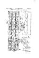
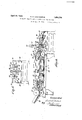
- FIGS. 1 and 2 taken together, constitute a plan view of the entire machine, omitting a few parts which need no illustration.
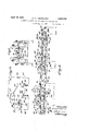
- Figure 3 represents a section on line 3-3 of Figure 1.
- Figure 4 represents a section on line 4-4 of Figure 2.
- Figure 5 represents a section on line 5-5 of Figures 1 and 3, omitting some parts.
- Figure 6 represents a section on line 6-6 of Figure 1.
- Figure 7 represents a section on line 7 -'l' of Figure 2.
- Figures 8 and '9 are views similar-to the left-hand portion of Figure .4, on a lar or scale, each of said Figures some parts in order to clearly.
- Figure 10 is an enlarged detail view of one of the pair of arresting fingers or stops and its mounting; r
- Figure 11 is an enlarged detail view of the nger mechanism which controls the operation of the stitchers.
- Figure 12 is a diagram of the mechanism and electrical connections controlled by the finger mechanism of- Figure 11.
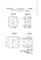
- Figure 13 is a plan view of one form of show others more blank upon which the machine illustrated opcrates, said view also lines the crease lines blanks are died out.
- Figure 14 is a plan view of the same blank after it has been folded and stitched.
- Figures 15 and 16 are views similar to Figures 13 and 14 but illustrating another form of blank upon which the machine will operate.
- the machine as a whole has primary and secondary folding mechanisms at an'angle to each other.
- FIG. 20 the-frame of the primary portion of the machine is indicated at 20, and the frame of the secondary portion of the machine isindicated at 21.
- a suitable table for a pile ofthe blanks to be acted upon is illustrated at 22. From said table the blanks are fed singly and successively by a combing wheel 23 carried by a shaft 24, and pass onto a carrier belt 25 mounted on pulleys 26, 27, and running over rolls mounted in a cage bar 28 which is suitably mounted in the frame of the machine in a permanent position along the mid-width of the primary portion of the machine.
- An upper carrier belt 29 is mounted at the far end on a pulley 30 carried by a driven shaft 31, the other end of the belt which is adjacent to the combing wheel being mounted on a small pulley 32.
- a small presser roll 33 carried by pivotally supported arms 34, each arm 34 having a spring 35 connected to it to cause the roll 33 toensure such pressureon each fed blank onto the carrier belt 25 as to enable the latter to frictionally advance the blank.
- the operative run of the upper belt 29 is held in contact with the lower belt by a series of rolls mounted in a cage bar 36 which is fixedly supported by tie rods 37 to occupy a permanent position along the mid-width of the primary portion-of the machine (see also Fig. 5).
- An important feature of the invention is that although the machine is capable of operating on a wide variety of sizes of blanks, a very rapid adjustment can be made to suit aparticular size. This is due to the fact that no lateral adjustment is ever required for the central members including the feed wheel, carrier belts and roll cages. all of which remain permanently at the mid-width of the machine. The only adjustment required for a different size is of the carriages which bear the folding devices. Said carriages are on opposite sides of the carrier belts 25, 29. and are simultaneously adjusted toward or from each other by right and left hand screws 38 rotatablv mounted in frame brackets 39 (Fig. 1).
- Said screws are provided with sprockets en aged by an endless chainas illustrated in igures 1 and 2, and either one of the screws may be turned by a suitable crank to effect simultaneous rotation of all of the screws.
- Each screw passes through an internally threaded projection of a sleeve 40 slidably mounted on a tie rod 37. The operation of this part of the machine will now be described.
- each of the sleeves 40 has a depending bracket 41 (Fig. 5) carrying upper and lower long guide strips 42, 43, between which side portions of the blanks pass as they travel with the carrier belts.
- the two lower guide strips 43 are mounted on vertical pins 44 mounted, preferably adjustably, in sleeves at the lower ends of the brackets 41, so that the space between each upper and lower guide strip can be varied to suit blanks of different thicknesses.
- the folder bars 45 are also supported by the brackets 41 of the sleeves 40.
- Each blank, with two opposite marginal wall or flap portions 1) b folded under the. body portion, is delivered by the nipper rolls 46, over a guide bar 47 (Figs. 1 and 3) and onto the platform which will now be described.
- the platform comprises plates 48, 50, 51, past or between which chains hereinafter described travel in a direction at a right angle to the path of travel which the blanks followed during their primary folding and delivery onto the platform .by the nipper rolls 46.
- Extending partly over the plate 51 is a plate 52 having its free edge curved upwardly to avoid liability of the arriving blank catching thereon, and to aid in guiding said arriving blank to position with its forward edge against an outer stop and guide bar 53.
- the following mechanism is provided Loosely mounted on the shaft 31 (Fig. l) are two sleeves 54 to which are secured, preferzibly adjustably, two rods 55 which support a lock curved yielding friction teeth or fingers, suitably of rubber.
- the said shaft and wheel are rotated in the direction of the arrow by a belt 59 mounted on and driven by a pulley 60 carried by the shaft 31, a tightener pulley 61 for the belt being carried by a block adjustably mounted on upright rods 62 supported by the block 56.
- the height of the brushing wheel 58 above f the platform may be varied to suit the character of the blanks operated upon.
- Such adjustment is effected by means of screws 63 carried by blocks mounted on a tie rod 37 (Fig. 3) and bearing on the rods 55. Since said rods 55 are practically pivotally supported on shaft 31, turning the screws 63 down results in raising the block 56 and the 'brush ing wheel, and vice versa.
- the friction fingers of the wheel 58 are so curved as to act not only frictionally in urging the lanks against the position-arresting bar or stop 53 but to also act yieldingly as pressers on the passing blanks, for a reason which will now be described.
- Said chains are mounted at one end on sprockets carried by driven shaft 66, and at the other end on sprockets carried by a shaft 68, said chains having lugs or pins 67 spaced at suitable intervals to act on the rear edge of each blank arriving on the platform and push it along under a guide bar 69 supported by tie rods 7 O.
- Said guide bar 69 is located at the mid-width of the first section of the secondary portion of the machine.
- FIG. 6 Another guide bar 71 (Fig. 6) suitably supported by tie rods 76 coacts with the bar 69 in guiding the mid-width portions of the blanks and preventing flexing or bending Igvhillela the portions d d are being acted upon y t e chine is being used in connection with articles of the form illustrated by Figures 15 and 16'.
- Each folded blank is taken from the chains 64 by upper and lower belts 74, 75 (Figs. 2, 4, 8 and 9) which are caused to travel at a higher speed than the chains 64, so that, as the ront portion of each blank is taken control of by said belts, its rear edge will be drawn away from the path of the pins down around the chain sprockets.
- reason for the higher speed of the belts is that since they carry the blanks to position where they will be briefly halted and stitched as presently described, it is important that each blank shall arrive at the stitching point sufficiently far inadvance of the next following one so that said, following one will not contact with the halted one.
- the two upper belts 74 are driven by pul leys 76 carried by shaft 77, and the coacting lower belts are driven by pulleys 78 carried by shaft 68.
- the gearing for operating said shafts and belts at the higher speed referred to may be such as illustrated in Figures 2, 8 and 9, or other suitable gearing;
- the upper runs of the lower belts are supported by idle rolls 79 (Fig. 9) and the lower runs of the upper belts are held in cooperative twisted folder bars 72, when the marelationship with the lower belts by yieldingly mounted rolls 80 carried by pivoted elbows having springs 81 connected to suitable fixed points.
- Said chains are mounted on sprockets 84, 86, car- I above the strip 89 is a bar 92 supported by tie I bars 93.
- vhich are of a wellknown type such as the Bostitch, will be referred to as a whole at A (Figs. 4, 8 and 9) and will be further referred to hereinafter.
- I provide a pair of yieldin pivoted fingers 94 (Figs. 2, 4, 7, 9 and 10 each pivoted at 95 to a block 96 mounted on bar 91 and connected by a spring 97 to a fixed pin 98 which normally holds the finger against a stop 99 with its lower end traversing the path of the blanks which are then being frictionally carried along by portions of the chains between forward and rearward lugs or pins thereof.
- the fingers 94 are sufficiently held by their springs 97 to temporarily detain each blank in position for the stitching, and when the done a pair of chain lugs 83 catches up with the rear edge of the blank, the two fingers yielding to permit the blank to be pushed past them.
- the chain lugs deliver the blanks to nipper rolls 100 and between u per and lower disks 101, 102 (Figs. 2 and 4
- The. upper disks 101 are carried by shaft 103, and the lower disks by shaft 104.
- the shafts and nipper rolls are connected by suitable gearing, and are rotated at sufficient speed to draw each blank from the chains 82 so that the lugs of the latter, when moving down around and with the sprockets 86, will not cut into the rear edges of the'blanks.
- the blanks are taken by a third pair of chains 105 having lugs or pins 106 which carry the folded blanks to nipper rolls 107 which deliver the completed articles to any suitable receiver, usually a wide, slowly travelling, belt.
- the carriages 108 for the chains 105 and the parts which cooperate therewith, are provided with brackets 109 mounted on tie rods 110 (Figs. 2 and 4) so as to be laterally shifted independently for different sizes or characters of the cartons.
- Said carriages have outwardly projecting pins 111 on which brackets 112 are adjustably mounted, said brackets supporting. breaker rods 113 and long bent strips or plates 114.
- the strips or plates 114 are so bent or formed and so positioned relatively to the breaker rods 113 that the portions of the cartons beyond the crease lines f first pass along between the rods 113 and the outer smooth surfaces of the strips 114 until they reach the portions of the strips which are substantially vertical and then, to
- the strips to the outer ends thereof and are thereby directed to a plane of travel that will ensure correct delivery to and between the er rolls 117.
- the rock-shaft 117 has a strip 121 to close an electric circuit when it contacts with a fixed contact 122 (Fig. 12) from which a wire 123. leads to a contact 124 below which is a spring contact 125.
- the two contact arms 124, 125 are carried by a fixed insulated block 126 mounted in any suitable portion of the machine. Pivoted at 127 below the contact 125 is a lever 128 one end of which acts on the contact 125 to close the circuit at 124, 125, when the roll 129 at the other end of the lever is acted upon by a cam 130 carried by shaft 131 which shaft may be any of the machine shafts that rotates once for passing blank.
- the timing is such that if there is no interruption in the regular continuity of foldedblanks being delivered by the belts 74, 75, the lever will close the circuit at 124, 125, in time for the closure to be also effected at 121, 122, by each passing blank.
- solenoid or equivalent magnets 133 a battery or other source of electricity 135, and wire 136, to the contact strip 121.
- each magnet core 137 acts on a lever138 to actuate a tripper 139, one for each stitcher A.
- the magnets and levers may be supported on brackets 140 se-' cured to the stitcher stands.
- each stitcher 1s of a duplex type to simultaneously apply stitches in two places, as indicated at m a: in Figures 14 and 16, and each has a pulley 141 carried by shaft 142 driven continuously by a belt 143 from a motor 144. But no stitching operation is effected except when both of the gaps at 121, 122 and 124, 125, are closed, resulting in operation of the trippers 139.
- the secondary portion comprises three sections the first of which includes the folders 72, when used, the second section includes the stitchers and the means for controlling the operations thereof, and the third section is the one which includes the breakers 113. Portions of the mechanisms in each of said three sections are independently adjustable as will now be described:
- each pair of screws 147, or 149 or 150 are rotated in unison by chain and sprocket gearing, and a suitable crank, in the same manner as lllustrated in connection with the screws 38 of the primary section illustrated in Figures 1 and 3.
- a machine for making a plurality of types of folded cartons said machine having travelling blank-carriers, folding devices in position at different distances along the carriers, and means for securing folded portions of the blanks to other ortions thereof, the folding devices in one 0 said positions being removable and replaceable to control the type of carton produced.
- a machine for making a plurality of types of folded and stitched cartons comprising primary and secondary secthe folding devices said machine comprising tions at an angle to each other, blank-carriers and folding devices in each section, and stitching mechanism in the secondary section, in the secondary section being removable and replaceable to control the type of carton produced.
- a blank-folding machine having primary and secondary portions at an angle to each other, a platform at the angle for receiving folded blanks from said primary portion, means for arresting movement of the blanks when delivered on the platform, and
- a rotary' member having yieldin friction fingers in position to urge the blanks toward said arresting means and to also press the blanks down on the platform.
- a blank-folding machine having primary and secondary portions at an angle to a rotar each other, a platform at the angle for receiving folded blanks from said primary portion, means for arresting'movement of the blanks when delivered on the platform, and
- a blank-folding and stitching machine having carriers provlded with pins for causing the blanks to travel toward a stop, mechanism in position to apply stitches to the blanks when they reach said stop, and means for increasing the speed of travel of the blanks betweensaid carriers and stop to draw the rear edges of the blanks away from the carrier pins.
- a blank-folding and stitching machine having a yieldable stop in the path of moving blanks, an endless carrier provided with pins for causing the blanks to travel toward said stop, mechanism in position to apply stitches to the blanks when they reach said stop, coacting belts to take the blanks from said carrier and move them toward said stop, and means to move said belts faster than said carrier to draw the rear edges of the blanks away from the carrier pins.
- a blank-folding and stitching machine having two sets of endless carriers provided with pins for causing the blanks to travel, one set being in advance of the other, means for temporarily stopping each blank after its arrival on the second set of carriers, means for increasing the speed of travel of each blank passing from the first to the second set of carriers, and means for applying stitches to each blank after its arrival on the said second set.
- a machine for producing fiat folded and stitched cartons said machine having means for first folding the blanks, an endless carrier for causing the folded blanks to travel, stitching mechanism and a yieldable stop intermediate the ends of said carrier, and means for causing the stitching mechanism to operate when a blank reaches said stop.
- a machine for producing flat folded and stitched cartons said machine having means for first folding the blanks, an endless carrier having pins for causing the folded blanks to travel, stitching mechanism and a yieldable stop intermediate the ends of said carrier, a movable member normall in the path of travel of a blank approachmg said stop, and means controlled by said movable member for causing the stitching mechanism to operate when a blank reaches said stop.
- a blank-folding and stitching machine having two sets of endless carriers having pins for causing the blanks to travel, one set being in advance of the other, the pins of the second set being spaced at greater distances than the pins of the first set, means for temporarily stopping each blank after its arrival on the second set of carriers, means for increasing the speed of travel of each blank passing from the first to the second set of carriers, and means for applying stitches to each blank after its arrival on the said second set.
- a machine for producing flat folded and stitched cartons said machine having stitching mechanism and means for causing folded cartons to travel toposition to be stitched, a finger in position to be displaced by a carton approaching position to be stitched, tripping mechanism for controlling the operation of the stitching mechanism, electric devices for controlling said tripping mechanism, and an electric circuit having two gaps, means being provided for continually closing and opening one of said gaps, and means connected with said finger for closing the other gap when a blank displaces the finger.
- a blank-folding machine comprising primary and secondary portions atan angle to each other, the secondary portion having a plurality of sections, the primary portion having laterally adjustable carriages including folding devices, and each section of the secondary portion having independent carriages including carrier chains, each'of said independent carriages being independently adjustable. 7 c
- a machine for making a plurality of types of folded cartons comprising travelling blank-carriers; folding devices 1n position at different distances along the carriers; and means for securing folded portions'of the blanks to other portions thereof, the folding.
- a machine for making a plurality of types of folded andsecured cartons comprismg primary and secondary sections at an angle to each other; blank-carriers and fold:
- a machine of the character described comprising a stop in the path of moving blanks; an'endless carrier for causing the blanks to travel toward said stop; mechanism in position to appl stitches to the blanks when they reach sald stop; elements to take the blanks from said carrier and move them toward said stop; and means for moving said elements at a speed faster than the speed of said carrier.
- a machine of the character described comprising means for folding the blanks; an endless carrier for causing the folded blanks to travel; stitching mechanism; a stop intermediate the ends of said carrier; and means for causin the stitching mechanism to operate on ailank when the latter reaches said stop. a l 20.
- a machine of the character described comprising an endless carrier for conveying partly folded cartons having weakened transverse lines; means to complete the folding of said cartons; securing mechanism; means for coordinating the feed of said carrier with the operation of said securing mechanism;
- the folding devices in the secondary section being operative or inoperative according to the type of carton to be produced.
- a blank-folding machine having primary and secondary portions at an an I to each other, folding mechanism in sai primary portion, a platform at said angle for receiving folded blanks-from said primary portion, means forarresting movement of the blanks when delivered on the platform, and
- a machine of the character described comprising carriers for causing the blanks to travel toward a stop, mechanism in position r to apply stitches to the blanks when they reach said stop, and means for increasing the
Landscapes
- Making Paper Articles (AREA)
Description
April 19, 1932. H.- s. LABOMBARDE AUTOMATIC FOLDING AND STITCHING SUIT BOX MACHIN Fil ed Aug. 15, 1928 7 Sheets-Sheet l flue afar a #0 ring April 19, 1932. H. s. LABOMBARDE I 1,854,798
AUTOMATIC FOLDING AND STITCHING SUIT. BOX MACHINE Filed Aug. 15, 1928 7 Sheets-Sheet 2 WJ W I Q. 4 j AN Inc/wafer 63 My ffoi'iig April 19, 1932. H. s. LABOMBARDE AUTOMATIC FOLDING AND STITCHING SUIT BOX MACHINE Filed Aug. l5, 1928 7 Sheets-Sheet 3 121062 itaz" QMJWM 19 N QSN H- S. LABOMBARDE Filed Aug. 15, 1928 D Q Q AUTOMATIC FOLDING AND STITCHING SUIT BOX MACHINE April 19, 1932;
April l9, 1932. H. s; LABOMBARDE' AUTOMATIC FOLDING AND STITCHING SUIT BOX MACHINE 7 Sheets-Sheet 5 Filed Aug. '15; 1928 April .19, 1932.
AUTOMATIC H. s. LABOMBARDE 1,854,798 FOLDING AND STITCHING SUIT BOX MACHINE Filed Aug. 1-5, 1928 7 Sheets-Sheet 6 L2 v e "for & M 64% Ly flffioz "nay April 1932- H. s. LABOMBARD'E 1,854,798
AUTOMATI FOLDING AND STITCHING SUIT BOX MACRINE Filed Au 15, 1928 7 Sheets-Sheet 7 X /c 8 l Z "i i a 6 I y' X 'l'ziveznor a fin fine y 10 certain portions of each Patented Apr. 19, 1932 UNITED STATES PATENT oFF cs HAROLD s, LA-ZBOMIBARDE, or NASHU'A, NEW HAMPSHIRE, nssrcnon T was: nm'ms- NATIONAL PAPER IBOX MACHINE PORATION 0]. v MAINE COMPANY, OF NASHUA, NEW A 003- AUTOMATIC FOLDING AND STITCHIN G SUI'Jl BOX Cm Application filed August 15, 1928. Ser1a1 No. 299,808
This invention relates to the manufacture of paper containers, and has particular reference to the production of that type of cartons known as suit boxes each of whlch usui ally consists of two members practically alike except. that one is slightly larger than the other.
There have been produced heretofore, machines which fold blanks, and stitch or staple blank together, and deliver them in flat folded condition; but so far as I am aware all have possessedsome obiections, notably lack of speed in producing the desired articles, due to the machine in- 15 eluding reciprocating operating members.
One of the objects of thepresent invention is to produce an improved machine for making flat folded and stitched cartons, all of the fi movably operating members of which ma- 150 chine are rotary or. otherwise continuous in movement, and which machine is, therefore,
capable of a very high speed of productlon.
Another object of the invention is to provide a machine which, according to the presence or absence of certain stationary folder members, is capable of producing, at equal speeds, either one of two different kinds of flat folded boxes or cartons.
Another object is to provide a machine having means for effecting a very quick adjustment (known as the set up) when a different size of blank is to be operated upon.
Another object is to provide a machine which not only converts blanks into flat 35 folded and secured boxes or cartons but also so acts on certain transverse crease lines of the otherwise completed articles as to break said lines in order to facilitate later setting up of the cartons by users.
With the above and other objects in view, which will be explained, the invention consists in the construction and combination of parts substantially as hereinafter described and claimed. v
Of the accompanying drawings:
Figures 1 and 2, taken together, constitute a plan view of the entire machine, omitting a few parts which need no illustration.
Figure 3 represents a section on line 3-3 of Figure 1.
Figure 4 represents a section on line 4-4 of Figure 2.
Figure 5 represents a section on line 5-5 of Figures 1 and 3, omitting some parts.
Figure 6 represents a section on line 6-6 of Figure 1.
Figure 7 represents a section on line 7 -'l' of Figure 2. r
Figures 8 and '9 are views similar-to the left-hand portion of Figure .4, on a lar or scale, each of said Figures some parts in order to clearly.
Figure 10 is an enlarged detail view of one of the pair of arresting fingers or stops and its mounting; r
Figure 11 is an enlarged detail view of the nger mechanism which controls the operation of the stitchers.
Figure 12 is a diagram of the mechanism and electrical connections controlled by the finger mechanism of- Figure 11.
Figure 13 is a plan view of one form of show others more blank upon which the machine illustrated opcrates, said view also lines the crease lines blanks are died out.
Figure 14 is a plan view of the same blank after it has been folded and stitched.
Figures 15 and 16 are views similar to Figures 13 and 14 but illustrating another form of blank upon which the machine will operate.
Similar reference characters indicate simillustrating by dotted usually made when the ilar parts or features in all of the views.
The machine as a whole has primary and secondary folding mechanisms at an'angle to each other.
To facilitate. an understanding of the invention, the followingpreliminary description is given:-
Assuming that blanks such as illustrated by Figure 15 are to beconverted to the flat folded and stitched condition illustrated by Figure 16, said blanks travel in the direction of the arrow 1 (Fig. 1-5) from the feed table 22 (Fig. 1) and travel to a platform at the angle of Figure 1, and while so travelling, the flaps b b and diagonally creased corners e e are folded down and flat under the sec- 8 and 9 omittmg tions (1 0. Then the so partially folded blanks travel from the platform in a right-angular direction (see arrow 2, Figs. and 16), and while so travelling, the narrow flaps d d are folded down and flat under the sections 0 and e, and farther along are stitched at a: 00. To effect this result all folding is done while travelling to the stitchers, and no folding is done after passing the stitchers.
To produce another type of carton (see Figs. 13 and 14) it is only necessary to remove the folding members which before acted on the narrow flaps d d, and to make a few adjustments to accord with the different shape of blanks and the required locations of the stitches w w.
Referring now to Figures 1 to 4, the-frame of the primary portion of the machine is indicated at 20, and the frame of the secondary portion of the machine isindicated at 21. A suitable table for a pile ofthe blanks to be acted upon is illustrated at 22. From said table the blanks are fed singly and successively by a combing wheel 23 carried by a shaft 24, and pass onto a carrier belt 25 mounted on pulleys 26, 27, and running over rolls mounted in a cage bar 28 which is suitably mounted in the frame of the machine in a permanent position along the mid-width of the primary portion of the machine.
An upper carrier belt 29 is mounted at the far end on a pulley 30 carried by a driven shaft 31, the other end of the belt which is adjacent to the combing wheel being mounted on a small pulley 32. Between the pulley 32 and the combing wheel is a small presser roll 33 carried by pivotally supported arms 34, each arm 34 having a spring 35 connected to it to cause the roll 33 toensure such pressureon each fed blank onto the carrier belt 25 as to enable the latter to frictionally advance the blank. The operative run of the upper belt 29 is held in contact with the lower belt by a series of rolls mounted in a cage bar 36 which is fixedly supported by tie rods 37 to occupy a permanent position along the mid-width of the primary portion-of the machine (see also Fig. 5).
An important feature of the invention is that although the machine is capable of operating on a wide variety of sizes of blanks, a very rapid adjustment can be made to suit aparticular size. This is due to the fact that no lateral adjustment is ever required for the central members including the feed wheel, carrier belts and roll cages. all of which remain permanently at the mid-width of the machine. The only adjustment required for a different size is of the carriages which bear the folding devices. Said carriages are on opposite sides of the carrier belts 25, 29. and are simultaneously adjusted toward or from each other by right and left hand screws 38 rotatablv mounted in frame brackets 39 (Fig. 1). Said screws are provided with sprockets en aged by an endless chainas illustrated in igures 1 and 2, and either one of the screws may be turned by a suitable crank to effect simultaneous rotation of all of the screws. Each screw passes through an internally threaded projection of a sleeve 40 slidably mounted on a tie rod 37. The operation of this part of the machine will now be described.
When the screws 38 are rotated, the sleeves 40 are slid simultaneously toward or from the carrier belts 25, 29, and their roll cages so that the guiding and folding devices which are supported by said sleeves will be farther from or nearer to said carrier belts and cages. Each of the sleeves 40 has a depending bracket 41 (Fig. 5) carrying upper and lower long guide strips 42, 43, between which side portions of the blanks pass as they travel with the carrier belts. The two lower guide strips 43 are mounted on vertical pins 44 mounted, preferably adjustably, in sleeves at the lower ends of the brackets 41, so that the space between each upper and lower guide strip can be varied to suit blanks of different thicknesses. Also supported by the brackets 41 of the sleeves 40 are the folder bars 45 (Figs. 1 and 5) which are so bent or inclined relatively to the guide strips as to fold the portions 6 b of the blanks down and under the body a before the blanks reach the nipper rolls 46. As all of these parts just described andwhich are supported by the sleeves 4O andtheir brackets are controlled as to their lateral positions both sides of the carrier belts, a single operation of the right and left hand screws 38 serves, as hereinbefore mentioned, to simultaneously effect all adjustments that are required when a different size of blank is to be operated upon, thereby effecting very quickly what is termed a set up of the machine. It is important, for this purpose, that the roll cages and carrier belts shall be fixed to remain in central position, as otherwise a reliable quick adjustment or set up could not be effected. 3
Each blank, with two opposite marginal wall or flap portions 1) b folded under the. body portion, is delivered by the nipper rolls 46, over a guide bar 47 (Figs. 1 and 3) and onto the platform which will now be described.
The platform comprises plates 48, 50, 51, past or between which chains hereinafter described travel in a direction at a right angle to the path of travel which the blanks followed during their primary folding and delivery onto the platform .by the nipper rolls 46. Extending partly over the plate 51 is a plate 52 having its free edge curved upwardly to avoid liability of the arriving blank catching thereon, and to aid in guiding said arriving blank to position with its forward edge against an outer stop and guide bar 53.
To aid in correctly locating each primarily folded blank on the platform, the following mechanism is provided Loosely mounted on the shaft 31 (Fig. l) are two sleeves 54 to which are secured, preferzibly adjustably, two rods 55 which support a lock curved yielding friction teeth or fingers, suitably of rubber. The said shaft and wheel are rotated in the direction of the arrow by a belt 59 mounted on and driven by a pulley 60 carried by the shaft 31, a tightener pulley 61 for the belt being carried by a block adjustably mounted on upright rods 62 supported by the block 56.
The height of the brushing wheel 58 above f the platform may be varied to suit the character of the blanks operated upon. Such adjustment is effected by means of screws 63 carried by blocks mounted on a tie rod 37 (Fig. 3) and bearing on the rods 55. Since said rods 55 are practically pivotally supported on shaft 31, turning the screws 63 down results in raising the block 56 and the 'brush ing wheel, and vice versa. Preferably the friction fingers of the wheel 58 are so curved as to act not only frictionally in urging the lanks against the position-arresting bar or stop 53 but to also act yieldingly as pressers on the passing blanks, for a reason which will now be described.
The blanks delivered on the platform have had their flaps or sections 12 1) (Figs. 14, 16) folded in under the sections a, and said sections 6 I) still have a tendency to spring back cording to the quality of the material employed for the suit boxes or cartons. The downward pressure however of the curved yielding friction fingers of the wheel ensures deposit of the preliminarily folded blanks sufficiently fiat on the platform to ensure their being properly engaged by the lugs or pins of the chains 64 which will now be described.
Each preliminarily folded blank arriving on the platform and squared up thereon by the mechanism just described, is immediately transferred in a right-angular direction by the chains 64 (Figs. 1, 2, 3, 4 and 6) which ride on rails or guide bars 65 which comprises the main members of two of the carriages hereinafter referred in connection with their lateral adjustabi-lity. Said chains are mounted at one end on sprockets carried by driven shaft 66, and at the other end on sprockets carried by a shaft 68, said chains having lugs or pins 67 spaced at suitable intervals to act on the rear edge of each blank arriving on the platform and push it along under a guide bar 69 supported by tie rods 7 O. Said guide bar 69 is located at the mid-width of the first section of the secondary portion of the machine.
Another guide bar 71 (Fig. 6) suitably supported by tie rods 76 coacts with the bar 69 in guiding the mid-width portions of the blanks and preventing flexing or bending Igvhillela the portions d d are being acted upon y t e chine is being used in connection with articles of the form illustrated by Figures 15 and 16'. Between the chains 64 and the folder bars 72 are guide strips 73 similar to the guide strips 42, 43, employed in the primary folding portion of the machine.
Each folded blank is taken from the chains 64 by upper and lower belts 74, 75 (Figs. 2, 4, 8 and 9) which are caused to travel at a higher speed than the chains 64, so that, as the ront portion of each blank is taken control of by said belts, its rear edge will be drawn away from the path of the pins down around the chain sprockets. reason for the higher speed of the belts is that since they carry the blanks to position where they will be briefly halted and stitched as presently described, it is important that each blank shall arrive at the stitching point sufficiently far inadvance of the next following one so that said, following one will not contact with the halted one.
The two upper belts 74 are driven by pul leys 76 carried by shaft 77, and the coacting lower belts are driven by pulleys 78 carried by shaft 68. The gearing for operating said shafts and belts at the higher speed referred to, may be such as illustrated in Figures 2, 8 and 9, or other suitable gearing;
The upper runs of the lower belts are supported by idle rolls 79 (Fig. 9) and the lower runs of the upper belts are held in cooperative twisted folder bars 72, when the marelationship with the lower belts by yieldingly mounted rolls 80 carried by pivoted elbows having springs 81 connected to suitable fixed points.
The belts 74, 7 5, tween the delivery the receiving ends 82 (Figs. 2, 4 and bridge a slight space heends of the chains 64 and of a second pair of chains 9) having pins 83. Said chains are mounted on sprockets 84, 86, car- I above the strip 89 is a bar 92 supported by tie I bars 93.
By comparing F igures 2, 3 and 9, it will be seen that the belts 74, 75,-extend some little distance past, or overlap, receiving ends of the chains 82. This, in connection with the timing of the sides of theoperation of the stitching is parts of the machine, is to ensure the proper delivery of each folded blank, by the belts to the chains. Such proper'delivery means that each blank should arrive on the chains with its front edge just behind a pair of chain lugs or pins and with its rear edge sufiiciently far in front of the next following In or pins to permit the blank to be momentari y arrested and stitched or stapled before said following lugs or pins reach the rear edge of the blank and commence to push it along. To permit proper and high-speedoperation, the pins 83 of the chains 82 are spaced farther apart than the pins of the chains 64.
For the present the two stitching and fastening mechanisms, vhich are of a wellknown type such as the Bostitch, will be referred to as a whole at A (Figs. 4, 8 and 9) and will be further referred to hereinafter.
To momentarily arrest each blank in exact position for stitching, I provide a pair of yieldin pivoted fingers 94 (Figs. 2, 4, 7, 9 and 10 each pivoted at 95 to a block 96 mounted on bar 91 and connected by a spring 97 to a fixed pin 98 which normally holds the finger against a stop 99 with its lower end traversing the path of the blanks which are then being frictionally carried along by portions of the chains between forward and rearward lugs or pins thereof.
The fingers 94 are sufficiently held by their springs 97 to temporarily detain each blank in position for the stitching, and when the done a pair of chain lugs 83 catches up with the rear edge of the blank, the two fingers yielding to permit the blank to be pushed past them.
After passing the fingers 94, the chain lugs deliver the blanks to nipper rolls 100 and between u per and lower disks 101, 102 (Figs. 2 and 4 The. upper disks 101 are carried by shaft 103, and the lower disks by shaft 104. The shafts and nipper rolls are connected by suitable gearing, and are rotated at sufficient speed to draw each blank from the chains 82 so that the lugs of the latter, when moving down around and with the sprockets 86, will not cut into the rear edges of the'blanks.
Next, the blanks are taken by a third pair of chains 105 having lugs or pins 106 which carry the folded blanks to nipper rolls 107 which deliver the completed articles to any suitable receiver, usually a wide, slowly travelling, belt.
The carriages 108 for the chains 105 and the parts which cooperate therewith, are provided with brackets 109 mounted on tie rods 110 (Figs. 2 and 4) so as to be laterally shifted independently for different sizes or characters of the cartons. Said carriages have outwardly projecting pins 111 on which brackets 112 are adjustably mounted, said brackets supporting. breaker rods 113 and long bent strips or plates 114.
16) are easily set upright The object of the members just described is important for the reason that the material of which the cartons are made is usually rather stiff and therefore unless the crease lines which are to define the angles of the cartons when they are manually converted by users to the form for receptacles and covers are easily bendable, it is difficult to effect proper conversion or setting up with all angle lines straight.
This feature of the invention will become plainer when it is understood that those sections of each blank which, while passing through the machine, are folded flat under and against other portions (see Figs. 14 and later. But there are other crease lines on which no folding is done by the machine. These are the crease lines 7 (see Figs. 13 to 16), and the purpose of the breaker rods 113 and strips 114 is to 3 effect a weakening of the crease lines f without completing folding of the portions of the blank which are beyond said lines. Each folded and stitched blank being carried along by the chains tion of the arrows 2 (Figs. 14 and 16) and the portions beyond the crease lines 7 at opposite sides of the machine, first pass along under the inclined rods 113 to an approximate vertical position so as to break said lines f to render the outer portions readily bendable later on said lines. This effect is roduced not only across the sections a c of the folded blank but also across the inwardly folded sections Figures 13 to 16 indicate crease lines made in the blanks and on which folding either is done by the machine or are needed to later facilitate manual conversion of the fiat folded cartons to condition for use. The strips or plates 114 are so bent or formed and so positioned relatively to the breaker rods 113 that the portions of the cartons beyond the crease lines f first pass along between the rods 113 and the outer smooth surfaces of the strips 114 until they reach the portions of the strips which are substantially vertical and then, to
render it certain that said temporarily flexed portions will be returned to outward fiat plane,
the strips to the outer ends thereof and are thereby directed to a plane of travel that will ensure correct delivery to and between the er rolls 117.
nip?
eferrlng now to the means for controlling stitchers A, the timing of operationis such that each folded blank drawn away from the chains 64 (Figs. 4 and 9') by the belts 74, 75, is delivered by the lat ter onto the chains 82 eral inches in advance of a pair of pins 83 so that said blank, then temporarily carried along frictionally by the chains, can be arrested by the yieldablestops 94 long enough to be stitched before said pair of pins reach the operations of the 105 travels in the direc- I b b. All dotted lines in they ride along the outer surfaces of with its rear edge sevr its rear edge and push it along past said stops. Said blank, on its way to said stops, lifts a finger 115 (Fig. 11) carried by a block 116 connectedto a short rock-shaft 117 mounted in a block 118 secured to a bar 92 and having o In the circuit described, there are a s ring 119 acting to normally hold the roc ing block 116 against a stop 120 and with the finger 115 lightly resting on the guide strip 89.
The rock-shaft 117 has a strip 121 to close an electric circuit when it contacts with a fixed contact 122 (Fig. 12) from which a wire 123. leads to a contact 124 below which is a spring contact 125. The two contact arms 124, 125, are carried by a fixed insulated block 126 mounted in any suitable portion of the machine. Pivoted at 127 below the contact 125 is a lever 128 one end of which acts on the contact 125 to close the circuit at 124, 125, when the roll 129 at the other end of the lever is acted upon by a cam 130 carried by shaft 131 which shaft may be any of the machine shafts that rotates once for passing blank. That is, the timing is such that if there is no interruption in the regular continuity of foldedblanks being delivered by the belts 74, 75, the lever will close the circuit at 124, 125, in time for the closure to be also effected at 121, 122, by each passing blank.
two gaps 1n series, one at 124, 125, which is continually closed and opened, and the other at 121, 122 which is only closed when a blank arrives in position to be stitched or stapled. The
5 rest of the circuit includes wire 132, two
.in Figures 14 and 16.
solenoid or equivalent magnets 133, a battery or other source of electricity 135, and wire 136, to the contact strip 121.
The reason for there being two magnets 133 is that there are two stitchers A A to apply staples or stitches'to the folded blanks in opposite portions thereof as indicated at w B When the circuit is completed at both of the gaps referred to, due to a folded blank actuating the finger 115, each magnet core 137 acts on a lever138 to actuate a tripper 139, one for each stitcher A. As illustrated in Figure 8, the magnets and levers may be supported on brackets 140 se-' cured to the stitcher stands. As both the stitching mechanism and its tripping device is well known and no particular structure thereof is claimed herein, detailed illustration and description thereof is omitted to avoid unnecessary prolixity. It is explained however that each stitcher 1s of a duplex type to simultaneously apply stitches in two places, as indicated at m a: in Figures 14 and 16, and each has a pulley 141 carried by shaft 142 driven continuously by a belt 143 from a motor 144. But no stitching operation is effected except when both of the gaps at 121, 122 and 124, 125, are closed, resulting in operation of the trippers 139.
It may be noticed that the spacing of the .nism is located in of the stitches relatively to each other is effected by ad ustments provided for in the well known stitchers A of the type illustrated and which adjustments need no description herein.
When the machine is employed for acting upon and producing such articles as illustrated by- Figures 15 and 16, the folders 72 are in place as illustrated in Figures 1 and 2, secured on pins 145 projecting from the carriage bars 73. Then in operation, after the portions 6 b have been primarily folded by the folders 45 (Figs. 1 and 5), the blanks travel along the secondary portion of the machine and the portions 0! d of the blanks are turned down under by the said folders 72 before the blanks reach the stitchers. The result is that the stitches a: :1: connect the portions 0 (1 together.
To enable the machine to be employed for acting upon and producing such articles as illustrated by Figures 13 and 14, it is only necessary to remove the folders 72- so that no folding is eflected while the blanks are travel- 1mg along the secondary portion of the mal of them, alongside some portions of the travelling carriers, and the stitching mechaposition to operate on the blanks while the latter are in the path of movement of said carriers.
While the primary portion of the machine comprises a single section, the secondary portion comprises three sections the first of which includes the folders 72, when used, the second section includes the stitchers and the means for controlling the operations thereof, and the third section is the one which includes the breakers 113. Portions of the mechanisms in each of said three sections are independently adjustable as will now be described:
It is desirable for some shapes or qualities of blanks, although not necessary for all, that in each of the three sections just referred to, the carriages for the chains and the parts which directly cooperate therewith shall be independently adjustable laterally. And of course, as is customary in all machines which employ adjustable chains mountedon sprockets, the sprockets are and are so connected with the carriages that when the latter are. moved laterally the sprockets are moved along their shafts. In the present machine the two carriages 73 of the first section are mounted on tie rods 146 (Figs. 2 and 4), and screws 147 mounted in splined on their shafts side portions of the frame, engage said car- In the second and third sections referred to,
of the secondary portion of the machine the carriages are similarly adjustable (see Fig.
4'), the carriages of the second section being supported on tie rods 148 andshiftedlaterally by screws 149, while the carriages of the third section are supported on the he rods 110 and are shifted laterally by screws 150. In practice each pair of screws 147, or 149 or 150, are rotated in unison by chain and sprocket gearing, and a suitable crank, in the same manner as lllustrated in connection with the screws 38 of the primary section illustrated in Figures 1 and 3.
Many members of the gearing illustrated in the drawings are left undescribed because the specific structure thereof is not claimed herein and may vary more or less without de arting from the present invention.
ldaving now described my invention, I claim i 1. A machine for making a plurality of types of folded cartons, said machine having travelling blank-carriers, folding devices in position at different distances along the carriers, and means for securing folded portions of the blanks to other ortions thereof, the folding devices in one 0 said positions being removable and replaceable to control the type of carton produced.
2. A machine for making a plurality of types of folded and stitched cartons, said machine comprising primary and secondary secthe folding devices said machine comprising tions at an angle to each other, blank-carriers and folding devices in each section, and stitching mechanism in the secondary section, in the secondary section being removable and replaceable to control the type of carton produced.
3. A machine for producing flat-folded cartons having weakened transverse lines,
primary and secondary portions at an angle to each other, blank-carriers and foldin devices in each of said portions of the machine, stitching mechanism in the second portion, and means beyond the stitching mechanism for bending the folded and stitched blanks on transverse lines.
4. A blank-folding machine having primary and secondary portions at an angle to each other, a platform at the angle for receiving folded blanks from said primary portion, means for arresting movement of the blanks when delivered on the platform, and
a rotary' member having yieldin friction fingers in position to urge the blanks toward said arresting means and to also press the blanks down on the platform.
5. A blank-folding machine having primary and secondary portions at an angle to a rotar each other, a platform at the angle for receiving folded blanks from said primary portion, means for arresting'movement of the blanks when delivered on the platform, and
series of lon itudinally curved flexible friction fingers 1n position to urge the blanks toward said arresting means and to also press the blanks down on the platform.
6. Ablank-folding and stitching machine having carriers provlded with pins for causing the blanks to travel toward a stop, mechanism in position to apply stitches to the blanks when they reach said stop, and means for increasing the speed of travel of the blanks betweensaid carriers and stop to draw the rear edges of the blanks away from the carrier pins. 7. A blank-folding and stitching machine having a yieldable stop in the path of moving blanks, an endless carrier provided with pins for causing the blanks to travel toward said stop, mechanism in position to apply stitches to the blanks when they reach said stop, coacting belts to take the blanks from said carrier and move them toward said stop, and means to move said belts faster than said carrier to draw the rear edges of the blanks away from the carrier pins.
8. A blank-folding and stitching machine having two sets of endless carriers provided with pins for causing the blanks to travel, one set being in advance of the other, means for temporarily stopping each blank after its arrival on the second set of carriers, means for increasing the speed of travel of each blank passing from the first to the second set of carriers, and means for applying stitches to each blank after its arrival on the said second set.
9. A machine for producing fiat folded and stitched cartons, said machine having means for first folding the blanks, an endless carrier for causing the folded blanks to travel, stitching mechanism and a yieldable stop intermediate the ends of said carrier, and means for causing the stitching mechanism to operate when a blank reaches said stop.
10. A machine for producing flat folded and stitched cartons, said machine having means for first folding the blanks, an endless carrier having pins for causing the folded blanks to travel, stitching mechanism and a yieldable stop intermediate the ends of said carrier, a movable member normall in the path of travel of a blank approachmg said stop, and means controlled by said movable member for causing the stitching mechanism to operate when a blank reaches said stop.
11. A blank-folding and stitching machine having two sets of endless carriers having pins for causing the blanks to travel, one set being in advance of the other, the pins of the second set being spaced at greater distances than the pins of the first set, means for temporarily stopping each blank after its arrival on the second set of carriers, means for increasing the speed of travel of each blank passing from the first to the second set of carriers, and means for applying stitches to each blank after its arrival on the said second set.
12. A machine for producing flat folded and stitched cartons, said machine having stitching mechanism and means for causing folded cartons to travel toposition to be stitched, a finger in position to be displaced by a carton approaching position to be stitched, tripping mechanism for controlling the operation of the stitching mechanism, electric devices for controlling said tripping mechanism, and an electric circuit having two gaps, means being provided for continually closing and opening one of said gaps, and means connected with said finger for closing the other gap when a blank displaces the finger.
13. A blank-folding machine comprising primary and secondary portions atan angle to each other, the secondary portion having a plurality of sections, the primary portion having laterally adjustable carriages including folding devices, and each section of the secondary portion having independent carriages including carrier chains, each'of said independent carriages being independently adjustable. 7 c
14. A machine for making a plurality of types of folded cartons comprising travelling blank-carriers; folding devices 1n position at different distances along the carriers; and means for securing folded portions'of the blanks to other portions thereof, the folding.
devices in one of said positions being operative or inoperative according to the type of carton to be produced.
15. A machine for making a plurality of types of folded andsecured cartons comprismg primary and secondary sections at an angle to each other; blank-carriers and fold:
ing devices in each section; and securing speed of travel of the blanks between said carriers and stop.
18. A machine of the character described comprising a stop in the path of moving blanks; an'endless carrier for causing the blanks to travel toward said stop; mechanism in position to appl stitches to the blanks when they reach sald stop; elements to take the blanks from said carrier and move them toward said stop; and means for moving said elements at a speed faster than the speed of said carrier. 1
19. A machine of the character described comprising means for folding the blanks; an endless carrier for causing the folded blanks to travel; stitching mechanism; a stop intermediate the ends of said carrier; and means for causin the stitching mechanism to operate on ailank when the latter reaches said stop. a l 20. A machine of the character described comprising an endless carrier for conveying partly folded cartons having weakened transverse lines; means to complete the folding of said cartons; securing mechanism; means for coordinating the feed of said carrier with the operation of said securing mechanism;
and means for bending the blanks on said transverse lines.
In testimony whereof I have afiixed my signature HAROLD S. LABOMBARDE.
mechanism in the secondary section, the folding devices in the secondary section being operative or inoperative according to the type of carton to be produced.
16. A blank-folding machine having primary and secondary portions at an an I to each other, folding mechanism in sai primary portion, a platform at said angle for receiving folded blanks-from said primary portion, means forarresting movement of the blanks when delivered on the platform, and
means for moving the blanks across said plat form at a speed substantially faster than the speed at which the blanks pass said folding mechanism.
17. A machine of the character described comprising carriers for causing the blanks to travel toward a stop, mechanism in position r to apply stitches to the blanks when they reach said stop, and means for increasing the
Priority Applications (1)
| Application Number | Priority Date | Filing Date | Title |
|---|---|---|---|
| US299803A US1854798A (en) | 1928-08-15 | 1928-08-15 | Automatic folding and stitching suit box machine |
Applications Claiming Priority (1)
| Application Number | Priority Date | Filing Date | Title |
|---|---|---|---|
| US299803A US1854798A (en) | 1928-08-15 | 1928-08-15 | Automatic folding and stitching suit box machine |
Publications (1)
| Publication Number | Publication Date |
|---|---|
| US1854798A true US1854798A (en) | 1932-04-19 |
Family
ID=23156368
Family Applications (1)
| Application Number | Title | Priority Date | Filing Date |
|---|---|---|---|
| US299803A Expired - Lifetime US1854798A (en) | 1928-08-15 | 1928-08-15 | Automatic folding and stitching suit box machine |
Country Status (1)
| Country | Link |
|---|---|
| US (1) | US1854798A (en) |
Cited By (1)
| Publication number | Priority date | Publication date | Assignee | Title |
|---|---|---|---|---|
| US2771292A (en) * | 1953-06-17 | 1956-11-20 | Samuel M Langston Co | Squaring devices for box closing machines |
-
1928
- 1928-08-15 US US299803A patent/US1854798A/en not_active Expired - Lifetime
Cited By (1)
| Publication number | Priority date | Publication date | Assignee | Title |
|---|---|---|---|---|
| US2771292A (en) * | 1953-06-17 | 1956-11-20 | Samuel M Langston Co | Squaring devices for box closing machines |
Similar Documents
| Publication | Publication Date | Title |
|---|---|---|
| US2589944A (en) | Machine for prebreaking, gluing, folding, delivering, and stacking creased carton blanks | |
| US3194126A (en) | Method and mechanism for aligning glued carton blanks | |
| US4057008A (en) | Carton erecting apparatus | |
| US2749967A (en) | Bookcase making machine | |
| US1979253A (en) | Carton blank folding and stapling machine | |
| US1571983A (en) | Paper-bag machine | |
| US2488674A (en) | Stacking device for folding machines | |
| US1854798A (en) | Automatic folding and stitching suit box machine | |
| US1765419A (en) | Envelope machine | |
| US1803698A (en) | Blank preparing mechanism for box making machines | |
| US2097301A (en) | Envelope machine | |
| US1736407A (en) | Envelope machine | |
| US2120214A (en) | Paper box making apparatus and method | |
| US3105418A (en) | Carton gluing and forming machine | |
| US1021325A (en) | Book or pamphlet making machine. | |
| US2701990A (en) | Box blank folding machine | |
| USRE18463E (en) | Envelope machine | |
| US2702190A (en) | Envelope stacking mechanism | |
| US1543374A (en) | Packaging machine | |
| US2584855A (en) | Box blank folding machine | |
| US1648252A (en) | Package-wrapping machine | |
| US1444004A (en) | Machine for making paper drinking cups, envelopes, and the like | |
| US1774536A (en) | Process and arrangement for manufacturing open-end and open-side envelopes from paper or similar material | |
| US2559235A (en) | Sheet feeding mechanism | |
| US2060501A (en) | Bread wrapping machine |