US1854791A - Gas extension light - Google Patents
Gas extension light Download PDFInfo
- Publication number
- US1854791A US1854791A US397621A US39762129A US1854791A US 1854791 A US1854791 A US 1854791A US 397621 A US397621 A US 397621A US 39762129 A US39762129 A US 39762129A US 1854791 A US1854791 A US 1854791A
- Authority
- US
- United States
- Prior art keywords
- light
- base
- extension light
- burner
- gas extension
- Prior art date
- Legal status (The legal status is an assumption and is not a legal conclusion. Google has not performed a legal analysis and makes no representation as to the accuracy of the status listed.)
- Expired - Lifetime
Links
- 239000007789 gas Substances 0.000 description 10
- HSFWRNGVRCDJHI-UHFFFAOYSA-N alpha-acetylene Natural products C#C HSFWRNGVRCDJHI-UHFFFAOYSA-N 0.000 description 3
- 125000002534 ethynyl group Chemical group [H]C#C* 0.000 description 3
- 230000000284 resting effect Effects 0.000 description 3
- 230000015572 biosynthetic process Effects 0.000 description 2
- 230000006835 compression Effects 0.000 description 2
- 238000007906 compression Methods 0.000 description 2
- 238000005755 formation reaction Methods 0.000 description 2
- -1 EXTENS ION Chemical class 0.000 description 1
- 230000006978 adaptation Effects 0.000 description 1
- 238000005553 drilling Methods 0.000 description 1
- 239000002184 metal Substances 0.000 description 1
- 210000002445 nipple Anatomy 0.000 description 1
Images
Classifications
-
- F—MECHANICAL ENGINEERING; LIGHTING; HEATING; WEAPONS; BLASTING
- F21—LIGHTING
- F21S—NON-PORTABLE LIGHTING DEVICES; SYSTEMS THEREOF; VEHICLE LIGHTING DEVICES SPECIALLY ADAPTED FOR VEHICLE EXTERIORS
- F21S13/00—Non-electric lighting devices or systems employing a point-like light source; Non-electric lighting devices or systems employing a light source of unspecified shape
Definitions
- the burner base 1 is flattened at its lights, and in certain features thereof particrearward portion 1a and is provided with a ularly for use in connection with acetylene drilling to receive the clamping bolt 1.
- the flood-light generators. V supporting frame 5 is preferably formed of m It will be understood, however, that its flat metal stock whichallows the arms 5ato 55 main features are equally adaptable for use spring toward each other and contact With the in connection with many other light sources, flattened portion of the burner base 1 when such, for instance, as tanks of compressed clamped thereto at any desired angle, by the acetylene or other illuminating gases. tightening of the wing nut 6.
- the stand- An object of this invention is to provide pipe clamping pieces 5?) are preferably weld- 60 f an extension light that may be carried or poed to the arms 5a thus becoming practically sitioned in places Where it would be inconintegral with the supporting frame 5. venient or impossible to convey or place the With the rim of the reflector 7 resting on generating apparatus. the ground, as in Fig. 3, the stability of the 1 Another object of this invention is to prolight is assured by the elongated formation 65 vide simple means by which the light is inof the base portion 50 of the supporting stantly adaptable to various positions and frame 5. purposes of use such as clamping it to the While the flexible gas conduit 8a in Fig.
- the stand-pipe of the generator at any desired 1 is shown as a short length and for the parangle of reflection; carrying in the hand; ticular purpose of arranging a double light hanging it upon a nail or other projection on the single apparatus stand-pipe, it will be or resting it on the ground where it may be understood that the flexible conduit 8 as porquickly adjusted to any desired angle of light tionally shown in Figs. 2, 3 and 4:, may be of direction. sufficient length to permit of positioning the Other objects and features of my invention extension light in places inaccessible to the will appear more fully from the following degenerating apparatus 9 and more or less rescription and accompanying drawings, in mote therefrom, such, for instance, as under whicha railroad wreck, or as being suspended from Fig.
- Fig. 2 shows the light as suspended from I claim:
- a'nail or, as may be, from some other sort of 1.
- a burner base In a gas extension light, a burner base,
- a supporting frame having formations com- Fig. 3 shows the light resting on the ground prising hand hold portions terminating in at one of the variously predeterminable anclamping arms and further including a gles of light reflection.
- ground rest portion which also serves as sus- Fig. 4 shows the light as carried by the pension means, and compression means for hand.
- securing said supporting frame to said burn- Fig. 5 is a'perspective view of my invener base at variably desired angles, the said tion minus the reflector. compression means, also serving to secure 45 Referring particularly to Fig. 5the burner the termini of said clamping arms to the base 1 is provided with a conduit nipple 2 stand-pine of a generating apparatus.
- the reflector shown as 7 in the reflector secured to said burner base, a supother drawings, may be secured to the burner porting frame pivotally connected to said 50 base 1 by screw-threaded or other desirable burner base, said frame comprising a memher having a looped portion, said looped portion having a flattened end face serving in cooperation with the rim of said reflector as a stable ground rest, and means for clamping said supporting frame to said burner base at variably desired angles.
- a burner base In a gas extension light, a burner base, a reflector secured to said burner-base, .a supporting frame comprising two members, and means for jointly pivotally connecting said two members to said burner base-at variably desired angles, one of said members having a looped portion, said looped portion having a flattened end face, said other member-being of less length than said looped member and terminating in a clamping portion, whereby optionally said members may cooperatively with one another serve to suspend the extension light from a suitable support or said one member cooperate with the rim of the reflector as a ground rest.
Landscapes
- Engineering & Computer Science (AREA)
- General Engineering & Computer Science (AREA)
- Gas Burners (AREA)
Description
April 19, 1932. w w, HARRls 1,854,791
GAS EXTENS ION LIGHT Filed Oct. 5, 1929 INVENTOR, Wi l Ham W. Harms BY {*1 k %W, HIS A ORNEYS.
Patented Apr. 19, 1932 j FFICE UNITED STATES PATENT? WILLIAM w. HARRIS, or imoox'ron, nassacnnsn'r'r GAS Extension mm Application filed October 5, 1929. Serial No. 397,621.
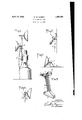
This invention relates to gas extension means. The burner base 1 is flattened at its lights, and in certain features thereof particrearward portion 1a and is provided with a ularly for use in connection with acetylene drilling to receive the clamping bolt 1. The flood-light generators. V supporting frame 5 is preferably formed of m It will be understood, however, that its flat metal stock whichallows the arms 5ato 55 main features are equally adaptable for use spring toward each other and contact With the in connection with many other light sources, flattened portion of the burner base 1 when such, for instance, as tanks of compressed clamped thereto at any desired angle, by the acetylene or other illuminating gases. tightening of the wing nut 6. The stand- An object of this invention is to provide pipe clamping pieces 5?) are preferably weld- 60 f an extension light that may be carried or poed to the arms 5a thus becoming practically sitioned in places Where it would be inconintegral with the supporting frame 5. venient or impossible to convey or place the With the rim of the reflector 7 resting on generating apparatus. the ground, as in Fig. 3, the stability of the 1 Another object of this invention is to prolight is assured by the elongated formation 65 vide simple means by which the light is inof the base portion 50 of the supporting stantly adaptable to various positions and frame 5. purposes of use such as clamping it to the While the flexible gas conduit 8a in Fig. stand-pipe of the generator at any desired 1 is shown as a short length and for the parangle of reflection; carrying in the hand; ticular purpose of arranging a double light hanging it upon a nail or other projection on the single apparatus stand-pipe, it will be or resting it on the ground where it may be understood that the flexible conduit 8 as porquickly adjusted to any desired angle of light tionally shown in Figs. 2, 3 and 4:, may be of direction. sufficient length to permit of positioning the Other objects and features of my invention extension light in places inaccessible to the will appear more fully from the following degenerating apparatus 9 and more or less rescription and accompanying drawings, in mote therefrom, such, for instance, as under whicha railroad wreck, or as being suspended from Fig. 1 shows my extension light clamped the arm of a derrick. on the stand-pipe of a portable acetylene gen- It will be obvious, from previous explanaerator of the type fully described in a 00- tion and by reference to the drawings, that pending application of even date herewith, the angle of light projection is quickly adand connected by a flexible gas conduit therejustable in all of the adaptations of the ino. T vention shown in the various figures.
Fig. 2 shows the light as suspended from I claim:
a'nail, or, as may be, from some other sort of 1. In a gas extension light, a burner base,
projection. a supporting frame having formations com- Fig. 3shows the light resting on the ground prising hand hold portions terminating in at one of the variously predeterminable anclamping arms and further including a gles of light reflection. ground rest portion which also serves as sus- Fig. 4 shows the light as carried by the pension means, and compression means for hand. securing said supporting frame to said burn- Fig. 5 is a'perspective view of my invener base at variably desired angles, the said tion minus the reflector. compression means, also serving to secure 45 Referring particularly to Fig. 5the burner the termini of said clamping arms to the base 1 is provided with a conduit nipple 2 stand-pine of a generating apparatus.
and with a gas passage therefrom to the 2. Ina gas extension light, aburner base, a burner 3. The reflector shown as 7 in the reflector secured to said burner base, a supother drawings, may be secured to the burner porting frame pivotally connected to said 50 base 1 by screw-threaded or other desirable burner base, said frame comprising a memher having a looped portion, said looped portion having a flattened end face serving in cooperation with the rim of said reflector as a stable ground rest, and means for clamping said supporting frame to said burner base at variably desired angles.
In a gas extension light, a burner base, a reflector secured to said burner-base, .a supporting frame comprising two members, and means for jointly pivotally connecting said two members to said burner base-at variably desired angles, one of said members having a looped portion, said looped portion having a flattened end face, said other member-being of less length than said looped member and terminating in a clamping portion, whereby optionally said members may cooperatively with one another serve to suspend the extension light from a suitable support or said one member cooperate with the rim of the reflector as a ground rest.
In testimony whereof I have signed this specification this 3rd day of October 1929. WILLIAM W. HARRIS.
Priority Applications (1)
| Application Number | Priority Date | Filing Date | Title |
|---|---|---|---|
| US397621A US1854791A (en) | 1929-10-05 | 1929-10-05 | Gas extension light |
Applications Claiming Priority (1)
| Application Number | Priority Date | Filing Date | Title |
|---|---|---|---|
| US397621A US1854791A (en) | 1929-10-05 | 1929-10-05 | Gas extension light |
Publications (1)
| Publication Number | Publication Date |
|---|---|
| US1854791A true US1854791A (en) | 1932-04-19 |
Family
ID=23571957
Family Applications (1)
| Application Number | Title | Priority Date | Filing Date |
|---|---|---|---|
| US397621A Expired - Lifetime US1854791A (en) | 1929-10-05 | 1929-10-05 | Gas extension light |
Country Status (1)
| Country | Link |
|---|---|
| US (1) | US1854791A (en) |
Cited By (3)
| Publication number | Priority date | Publication date | Assignee | Title |
|---|---|---|---|---|
| US3340648A (en) * | 1963-08-19 | 1967-09-12 | Northern Gas Products Company | Crop growth improvement by means of propane actuated thermopile |
| FR2082192A5 (en) * | 1970-03-06 | 1971-12-10 | Applic Gaz Sa | |
| EP2157355A1 (en) * | 2008-08-21 | 2010-02-24 | Snord Design, Lda. | Lightspot- An innovative gas appliance concept for a new lighting solution |
-
1929
- 1929-10-05 US US397621A patent/US1854791A/en not_active Expired - Lifetime
Cited By (3)
| Publication number | Priority date | Publication date | Assignee | Title |
|---|---|---|---|---|
| US3340648A (en) * | 1963-08-19 | 1967-09-12 | Northern Gas Products Company | Crop growth improvement by means of propane actuated thermopile |
| FR2082192A5 (en) * | 1970-03-06 | 1971-12-10 | Applic Gaz Sa | |
| EP2157355A1 (en) * | 2008-08-21 | 2010-02-24 | Snord Design, Lda. | Lightspot- An innovative gas appliance concept for a new lighting solution |
Similar Documents
| Publication | Publication Date | Title |
|---|---|---|
| US2739780A (en) | Fixture hanger assembly | |
| US3168252A (en) | Flexible fixture suspension | |
| US2723096A (en) | Hanger for mirrors and the like | |
| US2616645A (en) | Pipe hanger | |
| US5230559A (en) | Well light | |
| US2508974A (en) | Lantern holder | |
| US2747079A (en) | Trouble light and suspension means | |
| US1854791A (en) | Gas extension light | |
| US2446736A (en) | Suspension support for electric lighting fixtures | |
| US2706610A (en) | Flashlight holder | |
| US2710338A (en) | Portable lamp for mechanics' use | |
| US3182944A (en) | Ornamental lamp holder | |
| US1340273A (en) | Electric-light bracket | |
| US2371903A (en) | Floodlight bracket | |
| US3041035A (en) | Ceiling support for pendent electric fixtures and the like | |
| US2656454A (en) | Lantern and reflector holder having pivotally adjustable supporting arm | |
| US2367588A (en) | Combined fish sack holder and fishing pole rest | |
| US2065068A (en) | Portable electric lamp | |
| US3383082A (en) | Depending retractable mirror | |
| US1440694A (en) | Combination lamp stand and lamp protector | |
| US1622057A (en) | Portable wall bracket | |
| US2570329A (en) | Trouble light with tripod-forming support | |
| US558904A (en) | Thieds to albert nusser and frank baingo | |
| US2280523A (en) | Portable extension lamp | |
| US1499102A (en) | Portable lamp |