US1854789A - Treating materials with air - Google Patents
Treating materials with air Download PDFInfo
- Publication number
- US1854789A US1854789A US246455A US24645528A US1854789A US 1854789 A US1854789 A US 1854789A US 246455 A US246455 A US 246455A US 24645528 A US24645528 A US 24645528A US 1854789 A US1854789 A US 1854789A
- Authority
- US
- United States
- Prior art keywords
- air
- room
- door
- water
- thermostat
- Prior art date
- Legal status (The legal status is an assumption and is not a legal conclusion. Google has not performed a legal analysis and makes no representation as to the accuracy of the status listed.)
- Expired - Lifetime
Links
- 239000000463 material Substances 0.000 title description 12
- XLYOFNOQVPJJNP-UHFFFAOYSA-N water Substances O XLYOFNOQVPJJNP-UHFFFAOYSA-N 0.000 description 16
- 238000010438 heat treatment Methods 0.000 description 8
- 239000007921 spray Substances 0.000 description 6
- 238000009833 condensation Methods 0.000 description 5
- 230000005494 condensation Effects 0.000 description 5
- 230000003750 conditioning effect Effects 0.000 description 5
- 238000010276 construction Methods 0.000 description 3
- 238000004378 air conditioning Methods 0.000 description 2
- 238000000034 method Methods 0.000 description 2
- 241001527902 Aratus Species 0.000 description 1
- 241000905957 Channa melasoma Species 0.000 description 1
- 241001658031 Eris Species 0.000 description 1
- 239000001828 Gelatine Substances 0.000 description 1
- 241000208125 Nicotiana Species 0.000 description 1
- 235000002637 Nicotiana tabacum Nutrition 0.000 description 1
- 230000007547 defect Effects 0.000 description 1
- 238000001035 drying Methods 0.000 description 1
- 229920000159 gelatin Polymers 0.000 description 1
- 235000019322 gelatine Nutrition 0.000 description 1
- 239000003292 glue Substances 0.000 description 1
- 239000010985 leather Substances 0.000 description 1
- 239000007788 liquid Substances 0.000 description 1
- 238000004519 manufacturing process Methods 0.000 description 1
- 238000012986 modification Methods 0.000 description 1
- 230000004048 modification Effects 0.000 description 1
- 229920006395 saturated elastomer Polymers 0.000 description 1
- 239000000126 substance Substances 0.000 description 1
- 239000004753 textile Substances 0.000 description 1
- 238000010792 warming Methods 0.000 description 1
Images

Classifications
-
- F—MECHANICAL ENGINEERING; LIGHTING; HEATING; WEAPONS; BLASTING
- F26—DRYING
- F26B—DRYING SOLID MATERIALS OR OBJECTS BY REMOVING LIQUID THEREFROM
- F26B9/00—Machines or apparatus for drying solid materials or objects at rest or with only local agitation; Domestic airing cupboards
- F26B9/06—Machines or apparatus for drying solid materials or objects at rest or with only local agitation; Domestic airing cupboards in stationary drums or chambers
Definitions
- My invention relates to the overcoming of serious defects now existing in air conditioning apparatus specially constructed for treating or conditioning various materlals,
- gelatine, glue, or certain chemicals, and such like require relatively low temperatures with as low humidity as possible.
- the object of my invention is to overcome the difliculty .just referred to in a/ manner both responsive and sensitive and especially to safeguard an air-conditioned room the door of which is frequently and oftentimes carelessly opened or left open.
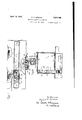
- Fig. 1 is a vertical section on
- line 11 of 2 is a horizontal of Flg. 1
- Fig. 3 is a vertical cross section on line 33 of Fig. 1.
- section of line I 1 indicates the walls of a room designed to carry out my invention, thesewalls being insulated (not 'shown) in any desired way, 2 being the floor on which the room is set.
- 3 are registers or the like, through which air 65 may be drawn down from the room for heatmg, and 4am ducts which lead the air from these registers and join at 5 where a blower fan 6 o any ordinary construction, or the like, Wlll draw the air'down through the registers 3 into the ducts 4 and drive it through an opening 7 into a heating chamber containing the radiator 8 or the like, by WhlCll it may be heated, into ducts 14 and through openmgs 141 into the room.
- the radiator is of ordinary construction and is fed by a steam pipe 9 and has its return pipe 10 w th a check valve 11 of any suitable type.
- 12 1 s an inlet valve for the steam supply and is of a kind well known, controlled by a thermostat 13 located on and near the top ofthe door or in other suitable place so that when the temperature of the room falls below a certain point, for example, when the door is opened the valve 12 controlled by the thermostat will open and allow steam immediately to pass into the radiator and a curtain of hot air to be thrown'across the door.
- the thermostat 13 will cause the valve-12 to close, shutting off steam from the radiator.
- This same thermostat also may control the fan 6 so that at the time the steam is turned on at 9 a blast of air will be caused to pass up through the radiator well heated 86 v for the purpose.
- the thermostat and its connections are well known in the art and are therefore not 90 described in .detail. Its various parts are marked 130. 131 is a coiled tube, part of the thermostat which permits the door to be opened.
- the ducts 14 carry the air which has passed through the radiator and distribute it through the openings 141 into what may be called a vestibule 15 in which is'also located the door 16 suitably hinged and adapted to be opened when required to capry In or remove goods from the interior of the chamber.
- ⁇ tank (arid At 18 is shown what I have called an ebulator or humidifier, such as is described in my United States Patent No. 1,606,? 63 of November 9, 1926. Its operation w1ll' be fully understood from my said-patent and is therefore merelyshown diagrammatlcally in the drawings. It comprises a fan 19 which draws the air up through an opemnfi 20 in the top of the room and forces it t rough the ebulator and through the corresponding opening 22 at the further end of the room.
- the necessary pump 231 to pump the water from this tank and deliver it to apparatus 232 contained about the shaft 24 so that as the air is drawn up by the fan it W111 be struck by jets of water delivered from tank 23 and will have the opportunityof absorbin all that it can therefrom, any surplus falling back into the tank.
- the tank water will become heated as it is repeatedly subjected to the influence of hot air passed through it and. will in time approximate the temperature of the air, but ordinarily will not exceed it. If for any reason the temperature of the as for example by the heating of a bearing forming part of the operating mechanism, then in such case the water is apt to heat the air to a temperature above that. desired to be maintained, and such tendency I have obviated in the following manner:
- the tank 23 is filled through the mec
- ipe 25 which is controlled by a ball cock anism 26 of the usual construction.
- thermostat 27 which is itself actuated by the temperature of the water in the tank.
- a valve in the outlet pipe 28 is opened by the thermostat and an amount of hot water is let out from the tank 23.
- This causes the ball cook 26 to open and allow fresh supply of 'colder water or other liquid to flow into'the tank through the pipe 25 until the temperature of the water causes the thermostat to close the valve 29.
- the water inthe tank 23 is prevented from becoming too hot.
- the setting of the tank thermostat this depending upon the desired temperature ofair to be maintained.
- the heating apparatus In starting up one of these air conditioning machines or rooms, the heating apparatus, whether it be steam, hot water, or electric, is first turned on to Warm the room several degrees above the required temperature when treating the. material.
- the heating apparatus must be thermostatically controlled and when the thermostat shuts ofi the heat, the
- the prior wa of the room before the 'condition'eris starte warms'the cold surfaces of the room (whatever they may bed) and the material therein.
- an ap aratus for conditioning materials comprising a substantially airtight room with an entrance thereto and a door closing said entrance, an air duct located inside the room at the side of the entrance with outlets therefrom opening onto the entrance wherebg air under pressure introduced into the not will be ejected to blanket said entrance, an apparatus for supnormally arranged inside the room adjacent said entrance whereby it will be influenced by atmospheric air when the door is opened to actuate said heating apparatus to supply 5 heated air under pressure to said duct.
- an apparatus for conditioning material comprising a substantially airtight room with anentrance thereto and an outwardl opening door closing said entrance, an air uct located inside the room at the side of the entrance with outlet therefrom opening onto the entrance whereby air under pressure introduced into the duct will be ejected to blanket said entrance, an apparatus for-supplying heated air under pressure to said room and connecting with said duct whereby heated air supplied to the room will be supplied by way of said duct, 9. thermostatic device connecting with said heating apparatus and normally arranged inside the room on said door whereby it will be influenced by atmospheric air when the door is opened to actuate said heating apparatus to supply heated air under pressure to said duct. DANIEL P. GOSLINE.
Landscapes
- Engineering & Computer Science (AREA)
- Mechanical Engineering (AREA)
- General Engineering & Computer Science (AREA)
- Central Heating Systems (AREA)
Description
April 19, 1932.
D. P. GOSLINE I 1,854,789
TREATING MATERIALS WITH AIR I Fil ed Jan. 1:5, 1928 2 Sheets-Sheet 1 ATT DRNELI '53 April 19, 1932. D. P..GQSLI NE TREATING MATERIJ KLS WITH AIR 2 Sheets-Sheet Filed Jan. 13, 1928 "Prams Apr. 1am;
PATENT: OFFICE miner. r. eosnnm; or nosron, mssacnusm'rs mamas-me murmurs wrrn Am Application fledjanu ary 13, 1928. Serial Ro.'2l=8,455.
My invention relates to the overcoming of serious defects now existing in air conditioning apparatus specially constructed for treating or conditioning various materlals,
some of which such as textiles, tobacco, leather for shoe making or in storage, must be submitted to high temperatures and high humidities to secure the desirable condition for manufacturing, while other classes of material, notably the drying of picture films,
" gelatine, glue, or certain chemicals, and such like, require relatively low temperatures with as low humidity as possible.
IWhen material requires high humldlty in its conditioning (often as high as 100% saturation) condensation and the consequent dripping of water on the material isbound to occur if the temperature drops a single degree. Such dripping discolors and spots the material so that it must be quickly removed to prevent complete loss. Materials requiring low temperatures and low humidities are spoiled if the conditioning process be interrupted or changed.
One especially disturbing factor is when outside or atmospheric air has permitted entrance to the contained air. At such time if there is a diiference between the condition of the outside air and inside the room, it will be understood, unless prevented by some means, the opening of the door to the room for any purpose will allow a rush of colder air inward and produce condensation, or, on the other hand, low humidities may lose the proper condition in the room so that the material being treated is likely to be spoiled.
The object of my invention is to overcome the difliculty .just referred to in a/ manner both responsive and sensitive and especially to safeguard an air-conditioned room the door of which is frequently and oftentimes carelessly opened or left open.
My invention will be understood by reference to the drawings, in which Fig. 1 is a vertical section on ,line 11 of 2 is a horizontal of Flg. 1, and
Fig. 3 is a vertical cross section on line 33 of Fig. 1.
section of line I 1 indicates the walls of a room designed to carry out my invention, thesewalls being insulated (not 'shown) in any desired way, 2 being the floor on which the room is set. 3 are registers or the like, through which air 65 may be drawn down from the room for heatmg, and 4am ducts which lead the air from these registers and join at 5 where a blower fan 6 o any ordinary construction, or the like, Wlll draw the air'down through the registers 3 into the ducts 4 and drive it through an opening 7 into a heating chamber containing the radiator 8 or the like, by WhlCll it may be heated, into ducts 14 and through openmgs 141 into the room. The radiator is of ordinary construction and is fed by a steam pipe 9 and has its return pipe 10 w th a check valve 11 of any suitable type. 12 1s an inlet valve for the steam supply and is of a kind well known, controlled by a thermostat 13 located on and near the top ofthe door or in other suitable place so that when the temperature of the room falls below a certain point, for example, when the door is opened the valve 12 controlled by the thermostat will open and allow steam immediately to pass into the radiator and a curtain of hot air to be thrown'across the door. When the room has been sufiiciently heated the thermostat 13 will cause the valve-12 to close, shutting off steam from the radiator. This same thermostat also may control the fan 6 so that at the time the steam is turned on at 9 a blast of air will be caused to pass up through the radiator well heated 86 v for the purpose.
Instead 'of using a steam radiator other means of heating the air blast may be used.
The thermostat and its connections are well known in the art and are therefore not 90 described in .detail. Its various parts are marked 130. 131 is a coiled tube, part of the thermostat which permits the door to be opened.
The ducts 14 carry the air which has passed through the radiator and distribute it through the openings 141 into what may be called a vestibule 15 in which is'also located the door 16 suitably hinged and adapted to be opened when required to capry In or remove goods from the interior of the chamber.
- exceeds that of the air,
\ tank (arid At 18 is shown what I have called an ebulator or humidifier, such as is described in my United States Patent No. 1,606,? 63 of November 9, 1926. Its operation w1ll' be fully understood from my said-patent and is therefore merelyshown diagrammatlcally in the drawings. It comprises a fan 19 which draws the air up through an opemnfi 20 in the top of the room and forces it t rough the ebulator and through the corresponding opening 22 at the further end of the room. It will be understood that there are provided at the water tank 23 the necessary pump 231 to pump the water from this tank and deliver it to apparatus 232 contained about the shaft 24 so that as the air is drawn up by the fan it W111 be struck by jets of water delivered from tank 23 and will have the opportunityof absorbin all that it can therefrom, any surplus falling back into the tank. The tank water will become heated as it is repeatedly subjected to the influence of hot air passed through it and. will in time approximate the temperature of the air, but ordinarily will not exceed it. If for any reason the temperature of the as for example by the heating of a bearing forming part of the operating mechanism, then in such case the water is apt to heat the air to a temperature above that. desired to be maintained, and such tendency I have obviated in the following manner: The tank 23 is filled through the mec
ipe 25 which is controlled by a ball cock anism 26 of the usual construction. There is, however, located in the water in the tank a thermostat 27 which is itself actuated by the temperature of the water in the tank. When the temperature of the water in the consequently the sprays) appreaches he danger point when it would unduly affect the air, thena valve in the outlet pipe 28 is opened by the thermostat and an amount of hot water is let out from the tank 23. This of course causes the ball cook 26 to open and allow fresh supply of 'colder water or other liquid to flow into'the tank through the pipe 25 until the temperature of the water causes the thermostat to close the valve 29. Thus the water inthe tank 23 is prevented from becoming too hot. Experience will indicate the setting of the tank thermostat, this depending upon the desired temperature ofair to be maintained.
In starting up one of these air conditioning machines or rooms, the heating apparatus, whether it be steam, hot water, or electric, is first turned on to Warm the room several degrees above the required temperature when treating the. material. The heating apparatus must be thermostatically controlled and when the thermostat shuts ofi the heat, the
' humidifier sprays are started, and a threethe duct 21 and down the water appreciably on the door and swin fold result will be seen, the hot dry. air of the room. commences to clrculate through the sprays and is somewhat saturated, second, the humidifier sprays are somewhat warmed, and third, the room temperature has been cooled a little because the hot air has been passed through the colder water sprays, consequently the heat control thermostat has turnedon the heat supply to keep up the temperature of the room, th1s operation continuing until the stipulated relative humidity is built up in the room.
The prior wa of the room before the 'condition'eris starte warms'the cold surfaces of the room (whatever they may bed) and the material therein. By this metho of first warming the room and the building up of the humidity to the desired percentage of saturation as the air ispassed through and throughthe sprays efiectually prevents condensation or dripping in a room so treated.
Owing to the fact that the hot air delivery ducts are placed either side of the doorway so that the hot air delivered bythem will cross blanketwise the entrance or vestibule into the room, an inrush of cold air into the heated room w' be prevented when the door is open. Moreover, the thermostat which controls the heat of the room is located outwardly with it, thus placing it in a col er atmosphere so that it will respond very quickly and will start the fan used for delivery of the hot air blast immediately upon the opening of the door. On this account condensation inside the room will be prevented by any inrush of cold air which otherwise might be effected, owin to the fact that the air within the room is 0 en humidified to a point approximating its saturation point and a variance of even one or two degrees might cause condensation.
It is evident to one skilled in the art that modifications of this apparatus may be made without departing from the spirit of my invention, by which the results above described may be secured, but I have found the above apparatus very efiective and very useful in keeping certam goods, manufactured or in process of manu acture, in a desirable con-' dition.
What I claim as my invention is:
1. In an ap aratus for conditioning materials, the com ination comprising a substantially airtight room with an entrance thereto and a door closing said entrance, an air duct located inside the room at the side of the entrance with outlets therefrom opening onto the entrance wherebg air under pressure introduced into the not will be ejected to blanket said entrance, an apparatus for supnormally arranged inside the room adjacent said entrance whereby it will be influenced by atmospheric air when the door is opened to actuate said heating apparatus to supply 5 heated air under pressure to said duct.
2. In an apparatus for conditioning material, the combination comprising a substantially airtight room with anentrance thereto and an outwardl opening door closing said entrance, an air uct located inside the room at the side of the entrance with outlet therefrom opening onto the entrance whereby air under pressure introduced into the duct will be ejected to blanket said entrance, an apparatus for-supplying heated air under pressure to said room and connecting with said duct whereby heated air supplied to the room will be supplied by way of said duct, 9. thermostatic device connecting with said heating apparatus and normally arranged inside the room on said door whereby it will be influenced by atmospheric air when the door is opened to actuate said heating apparatus to supply heated air under pressure to said duct. DANIEL P. GOSLINE.
Priority Applications (1)
| Application Number | Priority Date | Filing Date | Title |
|---|---|---|---|
| US246455A US1854789A (en) | 1928-01-13 | 1928-01-13 | Treating materials with air |
Applications Claiming Priority (1)
| Application Number | Priority Date | Filing Date | Title |
|---|---|---|---|
| US246455A US1854789A (en) | 1928-01-13 | 1928-01-13 | Treating materials with air |
Publications (1)
| Publication Number | Publication Date |
|---|---|
| US1854789A true US1854789A (en) | 1932-04-19 |
Family
ID=22930758
Family Applications (1)
| Application Number | Title | Priority Date | Filing Date |
|---|---|---|---|
| US246455A Expired - Lifetime US1854789A (en) | 1928-01-13 | 1928-01-13 | Treating materials with air |
Country Status (1)
| Country | Link |
|---|---|
| US (1) | US1854789A (en) |
Cited By (1)
| Publication number | Priority date | Publication date | Assignee | Title |
|---|---|---|---|---|
| EP2026026A1 (en) * | 2007-08-14 | 2009-02-18 | Aria-C S.R.L. | Drying apparatus |
-
1928
- 1928-01-13 US US246455A patent/US1854789A/en not_active Expired - Lifetime
Cited By (1)
| Publication number | Priority date | Publication date | Assignee | Title |
|---|---|---|---|---|
| EP2026026A1 (en) * | 2007-08-14 | 2009-02-18 | Aria-C S.R.L. | Drying apparatus |
Similar Documents
| Publication | Publication Date | Title |
|---|---|---|
| US1339374A (en) | Method of curing tobacco | |
| US2338382A (en) | Psychrometrically controeled jur | |
| US2022740A (en) | Air conditioning device | |
| CN107521303A (en) | For the method and system for preventing the mouldy of vehicle He avoiding mould smell | |
| US1467306A (en) | Method of and apparatus for drying and conditioning materials | |
| US1954455A (en) | Air conditioning apparatus | |
| US1854789A (en) | Treating materials with air | |
| US2718066A (en) | Laundry dryers | |
| US2082289A (en) | Tobacco curer | |
| US3526967A (en) | Pelt drying system | |
| US2969652A (en) | Heating, ventilating and cooling unit | |
| US1568717A (en) | Air-conditioning apparatus | |
| US1849061A (en) | Air conditioning equipment | |
| US2548313A (en) | Drier | |
| US1840565A (en) | Method of and apparatus for controlling temperature and humidity | |
| US2424927A (en) | Air heating and humidifying apparatus | |
| US1853853A (en) | System and apparatus for proof box conditioning | |
| US1280254A (en) | Mine ventilation. | |
| US2231824A (en) | Automatically controlled winter air conditioning system | |
| US1935305A (en) | Ventilating apparatus | |
| US1605634A (en) | Art of drying | |
| US1312759A (en) | stagey | |
| US2032628A (en) | Air heater and circulator for hop driers and the like | |
| US1866650A (en) | Air treating apparatus | |
| US2229942A (en) | Method for conditioning tobacco |