US1854788A - Apparatus for making tapestried brick - Google Patents
Apparatus for making tapestried brick Download PDFInfo
- Publication number
- US1854788A US1854788A US552136A US55213631A US1854788A US 1854788 A US1854788 A US 1854788A US 552136 A US552136 A US 552136A US 55213631 A US55213631 A US 55213631A US 1854788 A US1854788 A US 1854788A
- Authority
- US
- United States
- Prior art keywords
- brick
- bar
- column
- tapestried
- making
- Prior art date
- Legal status (The legal status is an assumption and is not a legal conclusion. Google has not performed a legal analysis and makes no representation as to the accuracy of the status listed.)
- Expired - Lifetime
Links
- 239000011449 brick Substances 0.000 title description 18
- 239000004927 clay Substances 0.000 description 10
- 230000003247 decreasing effect Effects 0.000 description 2
- 230000000694 effects Effects 0.000 description 2
- 230000002708 enhancing effect Effects 0.000 description 1
- 230000001788 irregular Effects 0.000 description 1
- 239000000463 material Substances 0.000 description 1
- 239000000203 mixture Substances 0.000 description 1
- 238000010408 sweeping Methods 0.000 description 1
Images
Classifications
-
- B—PERFORMING OPERATIONS; TRANSPORTING
- B28—WORKING CEMENT, CLAY, OR STONE
- B28B—SHAPING CLAY OR OTHER CERAMIC COMPOSITIONS; SHAPING SLAG; SHAPING MIXTURES CONTAINING CEMENTITIOUS MATERIAL, e.g. PLASTER
- B28B11/00—Apparatus or processes for treating or working the shaped or preshaped articles
- B28B11/08—Apparatus or processes for treating or working the shaped or preshaped articles for reshaping the surface, e.g. smoothing, roughening, corrugating, making screw-threads
- B28B11/0818—Apparatus or processes for treating or working the shaped or preshaped articles for reshaping the surface, e.g. smoothing, roughening, corrugating, making screw-threads for roughening, profiling, corrugating
-
- B—PERFORMING OPERATIONS; TRANSPORTING
- B28—WORKING CEMENT, CLAY, OR STONE
- B28B—SHAPING CLAY OR OTHER CERAMIC COMPOSITIONS; SHAPING SLAG; SHAPING MIXTURES CONTAINING CEMENTITIOUS MATERIAL, e.g. PLASTER
- B28B11/00—Apparatus or processes for treating or working the shaped or preshaped articles
- B28B11/08—Apparatus or processes for treating or working the shaped or preshaped articles for reshaping the surface, e.g. smoothing, roughening, corrugating, making screw-threads
Definitions
- This invention relates to improvements in apparatus for making tapestried brick and the like, and is a divisionof my pending application, Serial No. 422,586, filed January 22 1930.
- My invention contemplates an apparatus embodying means for forming and moving a continuous column of clay or other suitable material of the desired dimensions, and scoring means for forming a series of curved grooves or gutters on the surface of the column and on one or more faces of the resulting bricks, said means including an angularly rotatable head having an annular series of scoring pins thereon for engaging the moving column, and actuating mechanism therefor.
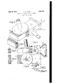
- Fig. 1 is a perspective view of the apparatus embodying my invention
- Fig. 2 is a similar view of one of the resulting bricks after severance from the column
- Fig. 3 is a view of the apparatus partly in side elevation and partly in section;
- Fig. 4 is a plan view of Fig. 3;
- Fig. 5 is an end view of asevered brick
- Fig. 6 is a plan view of such brick.
- A designates a portion of a brick machine adapted to contain a plastic clay mixture, and having a reciprocable plunger B therein for compressing and delivering the clay outwardly from a discharge nozzle 3, to form a continuous column or bar 2 of a desired shape and size.
- I provide a disk or head 5 suitably mounted on and rotatable by a driving shaft 7 above the top surface of the column or bar 2.
- the axis of said shaft and disk is inclined to the surface of the column 2, as particularly shown in Fig 3.
- the lower side of the disk 5 is provided with an annular series of spikes or pins 6 spaced radially in a plurality of series from the. outer edge of the disk inwardly, as shown.
- One'or both edges of the column or bar 2 may be treated in the same manner by means of a similar disk 5a rotatable by a shaft 7a, and having similar pins 6a thereon.
- Said disk and shaft are similarly tilted or inclined to the surface of the bar, so that the pins engage only at the side where the disk is closest to the bar. 'By such arrangement the pins beyond the center of either disk are elevated beyond the surface of the bar and do not out into it, except at the other or lowered side of the disk.
- the effect of such treatment is to impart a continuous series of such curved score marks across the face or faces of the bar, increasing a in depth towards the middle thereof and decreasing in depth from the middle towards the other edge.
- each severed brick is covered on its edge or end or ends with such plowed marks 4, as shown in Fig. 2.
- the curved score marks give to the faces of the brick an attractive or ornamental appearance, greatly enhancing its value in an artistic and novel manner.
- rotatable disks may be mounted by their drive shafts or other means so as to be adjusted towards or from the surface of the bar or with variation of inclination, and otherwise provided with suitable driving gearing and other necessary mechanism, in order to effect the operation to the best advantage.
- the speed of operation, spacing of the pins, number of annular rows, and other details of operative mechanism may be entirely within the control of the machine builder.
Landscapes
- Engineering & Computer Science (AREA)
- Structural Engineering (AREA)
- Chemical & Material Sciences (AREA)
- Ceramic Engineering (AREA)
- Mechanical Engineering (AREA)
- Devices For Post-Treatments, Processing, Supply, Discharge, And Other Processes (AREA)
Description
April 19, 1932. H. M. FENATI I 1,854,788
KING TAPESTRIED BRICK Filed July 21, 1931 INVE R.
a gwxl. a/maz A TTORNE Y.
Patented Apr. 19, 1932 UNITED STATES HUMIBERT M. FENATI, 0F NEW CASTLE, PENNSYLVANIA APPARATUS roa MAKING 'rArEsTRInD BRICK Original application filed January 22, 1930, Serial No. 422,586. Divided and this application filed July 21,
1931. Serial No. 552,136.
This invention relates to improvements in apparatus for making tapestried brick and the like, and is a divisionof my pending application, Serial No. 422,586, filed January 22 1930.
My invention contemplates an apparatus embodying means for forming and moving a continuous column of clay or other suitable material of the desired dimensions, and scoring means for forming a series of curved grooves or gutters on the surface of the column and on one or more faces of the resulting bricks, said means including an angularly rotatable head having an annular series of scoring pins thereon for engaging the moving column, and actuating mechanism therefor.
In the drawings, showing the invention somewhat diagrammatically:
Fig. 1 is a perspective view of the apparatus embodying my invention;
Fig. 2 is a similar view of one of the resulting bricks after severance from the column Fig. 3 is a view of the apparatus partly in side elevation and partly in section;
Fig. 4 is a plan view of Fig. 3;
Fig. 5 is an end view of asevered brick; and
Fig. 6 is a plan view of such brick.
Referring to the drawings, A designates a portion of a brick machine adapted to contain a plastic clay mixture, and having a reciprocable plunger B therein for compressing and delivering the clay outwardly from a discharge nozzle 3, to form a continuous column or bar 2 of a desired shape and size.
Various other well known means may be employed for extruding the plastic clay into a column or bar.
For the purpose of imparting a series of curving part circular score marks 4: of ragged outline and gutter or groove form, I provide a disk or head 5 suitably mounted on and rotatable by a driving shaft 7 above the top surface of the column or bar 2. The axis of said shaft and disk is inclined to the surface of the column 2, as particularly shown in Fig 3.
The lower side of the disk 5 is provided with an annular series of spikes or pins 6 spaced radially in a plurality of series from the. outer edge of the disk inwardly, as shown.
As the column or bar 2 ismovedjoutwardfrom the nozzle or dle 3, the d1sk5 1s rotated by its shaft 7, pins 6 sweeping around, over and throughtheupper surface of the clay column,
forming a continuous series of ragged, rough edge, irregular but regularly spaced curved lines or score marks 4.
One'or both edges of the column or bar 2 may be treated in the same manner by means of a similar disk 5a rotatable by a shaft 7a, and having similar pins 6a thereon. Said disk and shaft are similarly tilted or inclined to the surface of the bar, so that the pins engage only at the side where the disk is closest to the bar. 'By such arrangement the pins beyond the center of either disk are elevated beyond the surface of the bar and do not out into it, except at the other or lowered side of the disk. l
The effect of such treatment is to impart a continuous series of such curved score marks across the face or faces of the bar, increasing a in depth towards the middle thereof and decreasing in depth from the middle towards the other edge.
When it is cut or severed into the brick units, as by wire cutting, each severed brick is covered on its edge or end or ends with such plowed marks 4, as shown in Fig. 2. When the bricks are burned in the usual way, the curved score marks give to the faces of the brick an attractive or ornamental appearance, greatly enhancing its value in an artistic and novel manner.
It will be understood that the rotatable disks may be mounted by their drive shafts or other means so as to be adjusted towards or from the surface of the bar or with variation of inclination, and otherwise provided with suitable driving gearing and other necessary mechanism, in order to effect the operation to the best advantage.
The speed of operation, spacing of the pins, number of annular rows, and other details of operative mechanism may be entirely within the control of the machine builder.
What I claim isi 1. In brick making apparatus, the combination with means for forming a continuous moving bar of plastic clay, of a rotatable head located at an angle to the surface of the bar having an annular series of scoring pins.
2. In brick making apparatus, the combination with means for forming a continuous moving bar of plastic clay, of a rotatable series of scoring pins operable in an annular path in sloping relation to theface of the bar and traversing its surface at varying depth.
3. In nation with a machine for forming a continuous bar of plastic clay, of a rotatable series of scoring pins operable in an annular path within the width of the face of the bar being operated on and in a path non-parallel to the face of the bar.
- 4. In brick making apparatus, the combination with means for forming a continuous moving bar of plastic clay, of a rotatable series of scoring pins operable in an annular I path in sloping relation to the face of the bar adapted to engage the edge portion of the face at a minimum depth increasing towards its middle and decreasing in depth towards its opposite edge portion.
5. In brick making apparatus, the combination with means for'forming a continuous moving bar of plastic clay, of a rotatable head located at an angle to the surface of the bar having an annularly movable scoring pm.
In testimony whereof I hereunto aflix my signature.
HUMBERT M. FENATI.
brick making apparatus, the combi
Priority Applications (1)
| Application Number | Priority Date | Filing Date | Title |
|---|---|---|---|
| US552136A US1854788A (en) | 1930-01-22 | 1931-07-21 | Apparatus for making tapestried brick |
Applications Claiming Priority (2)
| Application Number | Priority Date | Filing Date | Title |
|---|---|---|---|
| US422586A US1849366A (en) | 1930-01-22 | 1930-01-22 | Method of making building bricks |
| US552136A US1854788A (en) | 1930-01-22 | 1931-07-21 | Apparatus for making tapestried brick |
Publications (1)
| Publication Number | Publication Date |
|---|---|
| US1854788A true US1854788A (en) | 1932-04-19 |
Family
ID=27025667
Family Applications (1)
| Application Number | Title | Priority Date | Filing Date |
|---|---|---|---|
| US552136A Expired - Lifetime US1854788A (en) | 1930-01-22 | 1931-07-21 | Apparatus for making tapestried brick |
Country Status (1)
| Country | Link |
|---|---|
| US (1) | US1854788A (en) |
Cited By (3)
| Publication number | Priority date | Publication date | Assignee | Title |
|---|---|---|---|---|
| DE1137370B (en) * | 1959-05-12 | 1962-09-27 | Fritz Homann A G | Method and device for producing thin lightweight panels from wood fibers |
| US5316465A (en) * | 1992-08-21 | 1994-05-31 | The Reinforced Earth Company | Apparatus for providing random rake finish in a cast concrete surface |
| US20050012232A1 (en) * | 2003-07-16 | 2005-01-20 | Rex Baxter | Apparatus and method for adjusting component features |
-
1931
- 1931-07-21 US US552136A patent/US1854788A/en not_active Expired - Lifetime
Cited By (4)
| Publication number | Priority date | Publication date | Assignee | Title |
|---|---|---|---|---|
| DE1137370B (en) * | 1959-05-12 | 1962-09-27 | Fritz Homann A G | Method and device for producing thin lightweight panels from wood fibers |
| US5316465A (en) * | 1992-08-21 | 1994-05-31 | The Reinforced Earth Company | Apparatus for providing random rake finish in a cast concrete surface |
| US20050012232A1 (en) * | 2003-07-16 | 2005-01-20 | Rex Baxter | Apparatus and method for adjusting component features |
| US6979189B2 (en) * | 2003-07-16 | 2005-12-27 | Rex Baxter | Apparatus and method for adjusting component features |
Similar Documents
| Publication | Publication Date | Title |
|---|---|---|
| US2720679A (en) | Universal die for forming tire tread | |
| US1976233A (en) | Grinding apparatus | |
| DE69613655T2 (en) | Glass cutting disc | |
| KR101262235B1 (en) | Cut working apparatus and method of non-slip road boundary stone using natural stone | |
| CN104191489B (en) | Ancient-imitation wood floorings surface indentation processing unit (plant) and processing method thereof | |
| US1854788A (en) | Apparatus for making tapestried brick | |
| US3073690A (en) | Method of grinding diamond-shaped recesses in metal-embossing roll | |
| US1908658A (en) | Machine for producing wall board | |
| US1849366A (en) | Method of making building bricks | |
| US4941949A (en) | Apparatus for manufacturing textured acoustical tile | |
| CN1011340B (en) | Method and apparatus for breaking up deposits and masonry in a rotary furnace | |
| US2655909A (en) | Flame finishing of granite surfaces | |
| DE606001C (en) | Cutting and grinding disc with a disc-shaped carrier made of metal | |
| US2262636A (en) | Method of and means for making tubular articles | |
| CN204136188U (en) | Ancient-imitation wood floorings surface indentation processing unit (plant) | |
| US2346393A (en) | Adjustable die for forming curved bricks | |
| DE512608C (en) | Device for shredding wood, in particular for the production of wood pulp | |
| US1672938A (en) | Method of making ornamental brick | |
| US1103631A (en) | Method of cutting ornamentation on glass articles. | |
| US1737551A (en) | Burr for dressing pulp grindstones | |
| US1204477A (en) | Process for manufacturing rough-faced brick. | |
| US1809572A (en) | Apparatus and process for texturing brick | |
| DE734853C (en) | Process for making tempered glass sheets | |
| US2125175A (en) | Method of removing metal from the surfaces of billets or similar metal bodies, and the product | |
| US1580153A (en) | Process for producing rough-texture brick |