US1854785A - Window construction - Google Patents
Window construction Download PDFInfo
- Publication number
- US1854785A US1854785A US420882A US42088230A US1854785A US 1854785 A US1854785 A US 1854785A US 420882 A US420882 A US 420882A US 42088230 A US42088230 A US 42088230A US 1854785 A US1854785 A US 1854785A
- Authority
- US
- United States
- Prior art keywords
- brick
- head
- extending
- rod
- jambs
- Prior art date
- Legal status (The legal status is an assumption and is not a legal conclusion. Google has not performed a legal analysis and makes no representation as to the accuracy of the status listed.)
- Expired - Lifetime
Links
- 238000010276 construction Methods 0.000 title description 28
- 239000011449 brick Substances 0.000 description 54
- 230000003014 reinforcing effect Effects 0.000 description 17
- 239000002184 metal Substances 0.000 description 12
- 239000004570 mortar (masonry) Substances 0.000 description 8
- 238000012986 modification Methods 0.000 description 4
- 230000004048 modification Effects 0.000 description 4
- 239000004568 cement Substances 0.000 description 2
- 239000013521 mastic Substances 0.000 description 2
- 238000000034 method Methods 0.000 description 2
- 230000002787 reinforcement Effects 0.000 description 2
- 230000015572 biosynthetic process Effects 0.000 description 1
- 230000000694 effects Effects 0.000 description 1
- 238000009428 plumbing Methods 0.000 description 1
Images
Classifications
-
- E—FIXED CONSTRUCTIONS
- E06—DOORS, WINDOWS, SHUTTERS, OR ROLLER BLINDS IN GENERAL; LADDERS
- E06B—FIXED OR MOVABLE CLOSURES FOR OPENINGS IN BUILDINGS, VEHICLES, FENCES OR LIKE ENCLOSURES IN GENERAL, e.g. DOORS, WINDOWS, BLINDS, GATES
- E06B1/00—Border constructions of openings in walls, floors, or ceilings; Frames to be rigidly mounted in such openings
- E06B1/04—Frames for doors, windows, or the like to be fixed in openings
- E06B1/24—Frames of natural stone, concrete, or other stone-like material
Definitions
- This invention relates to brickwindow construction where it is desired to use metal V the necessity of using a template ordinarily required in connection with the formation of windows in brick wall structures.
- Another object of the invention isto provide a means for reinforcing the transom
- head j'amb and mullions of the window structure and a method whereby these sections may be assembled on the ground, mortared and lifted intoplace, after the mortar has thoroughly set, and while the wall is being built up.
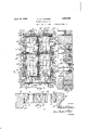
- Figure 1 is a front elevational view of a Window embodying the features of my in- O vention.
- Figure 2 is a. cross sectional line 2.2 of Fig. 1.
- Figure 3 isa vertical cross sectional view on the line 33 of Figure 1.
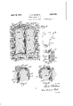
- Figure 4 shows the invention applied to a window of a different construction and showing the reinforcing means for the mullion.
- Figure 5 is a fragmentary view of a window embodying the invention and showing view on the face of the brick adjacent the opening 11 to a modification of the reinforcing means applied to the head jamb.
- F lgure 6 is a fragmentary view of a window showing a still further modification of the geinforcing means applied to the head
- Jam Figure 7 is a plan view of one of the brick.
- Figure 8 is a fragmentary portion ofa built up walla
- 10 represents the wall of a building composed of brick built up in the usual manner and provided with an opening 11, in thepresent instance a window opening, ofsuflicient size to receive the desired window casement.
- the brick sun rounding the opening have their edges beveled or tapered inwardly as shown at 11a, 11b and 110 to produce a neat appearance and to blend with the side jambs and head jamb as will be later described.
- a sill 12 is provided of brick having the upper portion of its exposed surface tapered or beveled inwardly at 120 as illustrated in Figs. 1. and 3.
- side jambs 13 Extending upwardly from the sill 12 and secured by mortar or other means to the inner vertical surfaces of the brick wall adjacent the opening 11 are side jambs 13 having their inner edges tapered or beveled inwardly as clearly shown in Fig. 2, the beveled or tapered surfaces preferably being a continuation of the tapered surfaces 11a and 110 of the brick Wall 10.
- a plurality of brick suitably secured together, by mortar or other means, to the inner surprovide a head jamb 14.
- the inner edges of the brick formingthe head jamb 1 are also tapered inwardly at an angle substantially a continuation of the beveled or tapered portion 112; of the brick surrounding the opening 11 in the main wall 10.
- Thehead jamb 14 is provided with a longi- 'tudinally extending rod 14?) which extends througheach of the brick forming the head j amb 145, theends of therod being supported.
- a transversely extending transom composed of brick suitably secured together by mortar or other means, having diverging tapered surfaces, and extending through the brick of the transom 15 is a rod 15a which has its ends extending beyond the ends of the transom 15, and supported within the intersectors 13?) disposed within the side jambs 13. If desired, the ends of the rod 15a may extend beyond the intersectors 13b and be additionallysupported upon the brick forming the main wall 10 as clearly shown in Fig. 1, thereby further supporting the transom 15 in addition to its support by the side jambs 13.
- This mullion 16 is provided with a longitudinally extending rod 16a, the ends of which extend beyond the ends of the mullion 16 and the upper end of the rod 16a is disposed within a suitable opening 14a in the under surface of an intersector 1 1b, forming part of the head jamb 14, while the lower end of the rod 160: is disposed within an opening 150 in the upper surface of an intersector 15?) which is part of the transom 15.
- a lower mullion composed of brick suitably secured together as before mentioned, and having inwardly diverging tapered surfaces. Extending longitudinally through the lower mullion 17 is a rod 17a, the ends of which extend beyond the ends of the mullion 17 and has its upper end disposed within an opening 150 in the lower surface of an intersector 15?) while the lower end of the rod 17 ais disposed within an opening 12?) in the upper surface of an intersector 12a of the sill 12.
- sill 12, side jambs 13, head amb 14:, transom 15, and mullions 16 and 17 cooperate to provide openings to receive the metal easements which will be hereinafter more fully described. 7 It might be further stated that extending inwardly into each of these openings referred to are flanges 18 preferably formed integral upon the rear edges of the brick surrounding the openings.
- the metal easements 19 clearly shown in Fig. 3 are adapted to be positioned within their respective openings and are adapted to engage with these flanges 18 so as to suitably position the metal casement with respect to the openings.
- a weather-tight oint is provided between the metal casement-s and the flanges 18 by interposing therebetween a mastic cement 20 which readily adheres to the metal casement 19 and the surfaces of the brick surrounding the openings.
- the particular feature of the present construction is the provision of a transom, head iamb, and mullions if desired, which may be built up as unit structures and inserted at the proper time during the building up of the wall proper.
- a transom, head iamb, and mullions if desired, which may be built up as unit structures and inserted at the proper time during the building up of the wall proper.
- the brick of the side jambs 13 are built up simultaneously therewith to a height at which the transom 15 is to be interposed.
- the transom 15 having been previously assembled, including the intersectors 13b, and the mortar securing the brick having properly set, the transom is then positioned upon the top of the side jambs 13, and the intersectors 13b aligned with the side jambs 13 wherein they are then secured in proper position by mortar or other means.
- the main wall 10 and the side jambs 13 are then built up jointly to a height at which the head jamb 14 is to be interposed into the structure.
- This head jamb 1 1, like the transom 15, is assembled as a unit and when the mortar has properly set is supported by the side iambs 13 through the extensions of the rod Ma. If desired, the ends of the rod 1 1a may extend beyond the side jambs into the wall proper and thus additional support is afiorded.
- the main wall 10 is then built up to the required height to complete the structure.
- the mullions 16 and 17 may either be built up in units as are the head jamb 14: and transom 15, or they may be built up simultaneously with the main wall 10, whichever is more convenient.
- the rod 17a extending through the mullion 17 has its ends positioned within the opening 12?) in the intersector 12 and opening 150 in the under side of the intersector 15?) respectively, while the ends of the rod 16a of the mullion 16 are disposed within the opening 150 in the upper surface of the intersector 15b, and the opening 140 in the under surface of the intersector 146 respectively.
- Thetransom' rod 15a and the head jamb rod 14a should be provided in continuous lengths and be of sufficient diameter to act as a reinforcing member. It should be noted that it will therefore be unnecessary to provide the usual reinforcing member upon the under side of the head jamb.
- the mullion 26 in Figure 4 is built up of brick similar to the brick 17 illustrated in Figure 1 and has extending longitudinally therethrough and vertically, as viewed in Figure 4, a reinforcing rod 26a.
- the lower end of the reinforcing rod 26a is disposed within an opening 225 in the intersector 22a suitably secured at a point substantially midway in the sill 22.
- the upper end of the reinforcing rod 26a extends considerably above the intersector 24?) in the head jambs 24 and is secured within the portion of the wall structure above the head jambs 24 as clearly indicated in dotted lines.
- the side jambs and wall construction generally, as shown in Figure 4 are built up in a manner similar to the manner in which the side jambs and wall structure are built up in Figure 1.
- the brick surrounding the window openings are provided with an inwardly extending flange or ledge 29 which acts as an abutment for the metal casement. The joint between the casement and the ledge may be produced in the manner already described.
- reinforcing means for the head ambs when formed in dome shape, and such reinforcing means is clearly illustrated in Figures 5 and 6 wherein different modifications are employed.
- the mullion 26 is built up in substantially the same manner as shown in Figure 4, but the adjacent portions of the head j ambs 24 are provided with continuously extending reinforcing rods 24a.
- the inner ends of the reinforcing rods 24a are secured within suitable openings in the intersector 24?) positioned at the terminus of the mullion 26 and the inner ends of the head jambs 24.
- the opposite ends of the rein forcing rods 24a are supported within suitable openings in the keystone brick 2461, thereby tending to reinforce the head janib at this point.
- This construction also affords the opportunity of building up that portion inforcing rods 24a at the inner portions of the head jambs 24.
- the reinforcing rods 24a are continuous throughout their length and extend through a plurality of brick.
- A- brick window construction comprising a sill, side jambs extending upwardly therefrom, and a head jamb provided with a rod engaging said side jambs.
- a brick window construction comprising a sill, side jambs extending upwardly therefrom, and a headjamb provided with a rod engaging said side jams, the inner surfaces of said sill, side jambs and head jamb being provided with a flange extending around the windowopening.
- a brick window construction comprising a sill, side jambs extending upwardly from said sill, a head jamb provided with a rod engaging said side j ambs, and a transom having a rod extending therethrough and engaging said side jalnbs.
- a brick window construction comprising a sill, side jambs extending upwardly from said sill, a head jamb, a transom provided with a rod extending therethrough and engaging said side jambs, and a mullion hav- 7 5.
- a brick window construction comprising a sill formed with an integral flange, side jambs extending upwardly therefrom provided with inwardly extending integral flanges in the same plane as the flange of said sill, and a head jamb provided with a 'rod extending therethrough, the ends of which are supported within said side jambs, said head jamb being provided with an integral flange in the same plane as the before mentioned flanges.
- a brick window construction comprising a sill provided with an opening in its upper surface, side jambs engaging the ends of said sill and each provided with a transverse opening between their ends and a further transverse opening at their upper ends, a head jamb provided with a rod having extended ends engaging the upper openings in said side jambs, said head jamb being provided with a transverse opening, a transom provided with a rod having extended ends engaging the openings in the side jambs between their ends, said transom being provided with transverse openings between its ends and extending on opposite sides thereof, and a mullion formed in two sections, each provided with a rod, the ends of one rod bein adapted'to engage the openings in the sill and the transom, and the others adapted to engage the openings in the transom and head jamb.
- a transom or head jamb for a brick window construction comprising a plurality of brick secured together to provide a unit and provided with an opening therethrough, and a rod extending through said opening and having its ends extending beyond the extremities of the brick.
- a brick window construction for use with metal easements comprising a plurality of brick surrounding an opening formed with integral flanges on their rear inner surfaces, a metal casement adapted to fit within the opening and engaging said flanges, and means for forminga weatherproof joint between the flanges and the metal casement.
- a brick window construction comprising a sill, side jambs extending upwardly therefrom, a head jamb associated with said side jambs, and a mullion provided with a longitudinally extending rod or rods extending therethrough, the ends of which extend beyond the ends of said mullion and cooperate with said sill and head jamb respectively.
- a brick window construction comprising a sill, side jambs extending upwardly therefrom, a head jamb provided with a longitudinally extending rod extending therethrough the ends of which are supported upon I said side jambs, and a mullion having a longitudinally extending rod or rods extending therethrough, the ends of which extend beyond the ends of said mullion and cooperate with said head jamb and sill respectively.
- a brick window construction comprising a sill, side jambs extending upwardly therefrom, and a substantially dome-shaped head jamb engaging said side jambs, the joining portions of said head jamb and said side jambs being provided with a reenforcement.
- a brick window construction comprising a sill, side jambs extending upwardly therefrom, a substantially dome-shaped head jamb engaging said side jambs, and reenforcing means extending through a portion of the brick at the joints between the head jamb and the side jambs.
- a brick window construction comprising a sill, side jambs extending upwardly therefrom, a substantially dome-shaped head jamb engaging said side jambs, and a plurality of reenforcing members for the brick forming the joints between the head jamb and the side j ambs, each member being disposed within the adjacent brick and extending through the joint therebetween.
- a brick window construction comprising a sill, side jambs extending upwardly therefrom, a substantially dome-shaped head jamb engaging said side jambs, a mullion extending upwardly between the side jambs, a reenforcing member extending longitudinally of said mullion and having one end secured within said sill and the other end secured Within the wall structure adjacent the dome shaped head j amb, laterally extending portions supported upon said mullion and terminating in said head amb, and reenforcing members for said laterally extending portions.
Landscapes
- Engineering & Computer Science (AREA)
- Civil Engineering (AREA)
- Structural Engineering (AREA)
- Door And Window Frames Mounted To Openings (AREA)
- Load-Bearing And Curtain Walls (AREA)
Description
April 19, 1932. c. G. DECKMAN 1,854,735
I WINDOW CONSTRUCTION Filed Jan. 15, 1930 Z'Sheets-Sheet 1 a0 3 4 I7 L ]8 l/ a: a: t I INVENTOR 1r [3 75 I I W 565 ATTORNEY$ April 19, 3 1 c. G. DECKMAN 1,854,785
\- i WINDOW CONSTRUCTION Filed Jan. 15, 1950 2 Sheets-Sheet 2 ZW M QM ATTORNEY I 35 lating thereto as Patented Apr. 19, 1932 UNITED STATES CHARLES G. DECKMAN, OF CLEVELAND, OHIO, ASSIGNOR TO THE MEDAL BRICK 8c TILE COMPANY, OF CLEVELAND, OHIO, A CORPORATION OF OHIO WINDOW CONSTRUCTION Application filed January 15, 1930. Serial No. 420,882.
This application is a continuationin part of my co-pending application, Serial No. 123,662,. filed July 20, 1926. r
. This invention relates to brickwindow construction where it is desired to use metal V the necessity of using a template ordinarily required in connection with the formation of windows in brick wall structures.
Another object of the invention isto provide a means for reinforcing the transom,
head j'amb and mullions of the window structure and a method whereby these sections may be assembled on the ground, mortared and lifted intoplace, after the mortar has thoroughly set, and while the wall is being built up.
With the objects above indicated and other objects hereinafter explained in view, my invention consists in the construction and combination of elements and the method rehereinafter described and claimed.
Referring to the drawings: Figure 1 is a front elevational view of a Window embodying the features of my in- O vention.
Figure 2 is a. cross sectional line 2.2 of Fig. 1.
Figure 3 isa vertical cross sectional view on the line 33 of Figure 1.
Figure 4 shows the invention applied to a window of a different construction and showing the reinforcing means for the mullion.
Figure 5 is a fragmentary view of a window embodying the invention and showing view on the face of the brick adjacent the opening 11 to a modification of the reinforcing means applied to the head jamb.
F lgure 6 is a fragmentary view of a window showing a still further modification of the geinforcing means applied to the head Jam Figure 7 is a plan view of one of the brick.
Figure 8 is a fragmentary portion ofa built up walla In the drawings 10 represents the wall of a building composed of brick built up in the usual manner and provided with an opening 11, in thepresent instance a window opening, ofsuflicient size to receive the desired window casement. The brick sun rounding the opening have their edges beveled or tapered inwardly as shown at 11a, 11b and 110 to produce a neat appearance and to blend with the side jambs and head jamb as will be later described. i At the lower portion of the window openmg 11 a sill 12 is provided of brick having the upper portion of its exposed surface tapered or beveled inwardly at 120 as illustrated in Figs. 1. and 3.
Extending upwardly from the sill 12 and secured by mortar or other means to the inner vertical surfaces of the brick wall adjacent the opening 11 are side jambs 13 having their inner edges tapered or beveled inwardly as clearly shown in Fig. 2, the beveled or tapered surfaces preferably being a continuation of the tapered surfaces 11a and 110 of the brick Wall 10.
At the upper portion oflthe opening 11 and extending between the side jambs 13 are a plurality of brick suitably secured together, by mortar or other means, to the inner surprovide a head jamb 14. The inner edges of the brick formingthe head jamb 1 are also tapered inwardly at an angle substantially a continuation of the beveled or tapered portion 112; of the brick surrounding the opening 11 in the main wall 10.
preferably by the upper ends of the side jambs 13.
Midway between the sill 12 and the head jamb 14 is a transversely extending transom composed of brick suitably secured together by mortar or other means, having diverging tapered surfaces, and extending through the brick of the transom 15 is a rod 15a which has its ends extending beyond the ends of the transom 15, and supported within the intersectors 13?) disposed within the side jambs 13. If desired, the ends of the rod 15a may extend beyond the intersectors 13b and be additionallysupported upon the brick forming the main wall 10 as clearly shown in Fig. 1, thereby further supporting the transom 15 in addition to its support by the side jambs 13.
Extending vertically between the side jambs 13, and between the head jamb 14 and the transom 15, is an upper mullion 16 having inwardly diverging tapered surfaces, the mullions being composed of suitable brick secured together by mortar or other means. This mullion 16 is provided with a longitudinally extending rod 16a, the ends of which extend beyond the ends of the mullion 16 and the upper end of the rod 16a is disposed within a suitable opening 14a in the under surface of an intersector 1 1b, forming part of the head jamb 14, while the lower end of the rod 160: is disposed within an opening 150 in the upper surface of an intersector 15?) which is part of the transom 15.
At 17 is indicated a lower mullion composed of brick suitably secured together as before mentioned, and having inwardly diverging tapered surfaces. Extending longitudinally through the lower mullion 17 is a rod 17a, the ends of which extend beyond the ends of the mullion 17 and has its upper end disposed within an opening 150 in the lower surface of an intersector 15?) while the lower end of the rod 17 ais disposed within an opening 12?) in the upper surface of an intersector 12a of the sill 12.
It will, therefore, be noted that the sill 12, side jambs 13, head amb 14:, transom 15, and mullions 16 and 17 cooperate to provide openings to receive the metal easements which will be hereinafter more fully described. 7 It might be further stated that extending inwardly into each of these openings referred to are flanges 18 preferably formed integral upon the rear edges of the brick surrounding the openings.
It has been very difficult heretofore to use metal casement windows in brick constructions because of the inability to obtain a weatherproof joint between the brick wall and the casement. In fact, it has been a very serious matter and has greatly hampered the use of these metal windows which are becoming more in demand. The provision of these flanges 18 upon the inner surfaces of the brick enables the casement to be applied to the opening from the outside and provides a snug fit and affords an efficient means to prevent calking or pointing with mastic cement to thereby obtain a waterproof joint.
In forming or building up the window herein described care should be taken in plumbing the jambs. The special feature of this construction is that no template is required.
The metal easements 19 clearly shown in Fig. 3 are adapted to be positioned within their respective openings and are adapted to engage with these flanges 18 so as to suitably position the metal casement with respect to the openings. A weather-tight oint is provided between the metal casement-s and the flanges 18 by interposing therebetween a mastic cement 20 which readily adheres to the metal casement 19 and the surfaces of the brick surrounding the openings.
The particular feature of the present construction is the provision of a transom, head iamb, and mullions if desired, which may be built up as unit structures and inserted at the proper time during the building up of the wall proper. For example, assuming the wall 10 is being built up around the opening 11, the brick of the side jambs 13 are built up simultaneously therewith to a height at which the transom 15 is to be interposed. The transom 15 having been previously assembled, including the intersectors 13b, and the mortar securing the brick having properly set, the transom is then positioned upon the top of the side jambs 13, and the intersectors 13b aligned with the side jambs 13 wherein they are then secured in proper position by mortar or other means. The main wall 10 and the side jambs 13 are then built up jointly to a height at which the head jamb 14 is to be interposed into the structure. This head jamb 1 1, like the transom 15, is assembled as a unit and when the mortar has properly set is supported by the side iambs 13 through the extensions of the rod Ma. If desired, the ends of the rod 1 1a may extend beyond the side jambs into the wall proper and thus additional support is afiorded. The main wall 10 is then built up to the required height to complete the structure.
If the mullions 16 and 17 are to be employed they may either be built up in units as are the head jamb 14: and transom 15, or they may be built up simultaneously with the main wall 10, whichever is more convenient. In either respect the rod 17a extending through the mullion 17 has its ends positioned within the opening 12?) in the intersector 12 and opening 150 in the under side of the intersector 15?) respectively, while the ends of the rod 16a of the mullion 16 are disposed within the opening 150 in the upper surface of the intersector 15b, and the opening 140 in the under surface of the intersector 146 respectively.
Thetransom' rod 15a and the head jamb rod 14a should be provided in continuous lengths and be of sufficient diameter to act as a reinforcing member. It should be noted that it will therefore be unnecessary to provide the usual reinforcing member upon the under side of the head jamb.
The provision of the rods extending through the brick comprisingthe head amb 14 and transom 15 serve as reinforcements and as a result no window templet is required.
In Figures 4, 5 and 6 the same idea is maintained in building up the window structure. However, the head jambs 24 are dome shaped requiring, in some instances, as shown particularly in Figures 5 and'6, a somewhat different for-m of reinforcing means with respect to the head jamb.
The type of construction disclosed in Figure 4 does not require any reinforcing means in the head jambs 24 due to t-hekeystone effect of the brick 24:6Z at the apex of the head jambs. r
The mullion 26 in Figure 4 is built up of brick similar to the brick 17 illustrated in Figure 1 and has extending longitudinally therethrough and vertically, as viewed in Figure 4, a reinforcing rod 26a. The lower end of the reinforcing rod 26a is disposed within an opening 225 in the intersector 22a suitably secured at a point substantially midway in the sill 22. The upper end of the reinforcing rod 26a extends considerably above the intersector 24?) in the head jambs 24 and is secured within the portion of the wall structure above the head jambs 24 as clearly indicated in dotted lines. The side jambs and wall construction generally, as shown in Figure 4, are built up in a manner similar to the manner in which the side jambs and wall structure are built up in Figure 1. Further, the brick surrounding the window openings are provided with an inwardly extending flange or ledge 29 which acts as an abutment for the metal casement. The joint between the casement and the ledge may be produced in the manner already described.
In some instances it might be found desirable to provide reinforcing means for the head ambs when formed in dome shape, and such reinforcing means is clearly illustrated in Figures 5 and 6 wherein different modifications are employed.
In Figure 5 the mullion 26 is built up in substantially the same manner as shown in Figure 4, but the adjacent portions of the head j ambs 24 are provided with continuously extending reinforcing rods 24a. The inner ends of the reinforcing rods 24a are secured within suitable openings in the intersector 24?) positioned at the terminus of the mullion 26 and the inner ends of the head jambs 24. The opposite ends of the rein forcing rods 24a are supported within suitable openings in the keystone brick 2461, thereby tending to reinforce the head janib at this point. This construction also affords the opportunity of building up that portion inforcing rods 24a at the inner portions of the head jambs 24. It will be noted that in this particular instance the reinforcing rods 24a are continuous throughout their length and extend through a plurality of brick.
Vith respect to Figure 6., it is sometimes found convenient to provide reinforcing means for the head jambs in the forms of short lengths of rod or pins 34a in the head jamb 34. In this instance the pins are'disposed within suitable openings in the faces of adjacent brick. This form of reinforcement is quite desirable when the head jambs are built up during the construction of the wall proper .and not as individual units. These pins can be readily inserted as the brick are being laid and tend to reinforce the head jambs in a manner similar to that already described.
WVhile I have described the preferred embodiment of the invention, it is to be understood that I am not to be limited thereto, as changes and modifications may be resorted to without departing from the spirit of the invention as defined in the appended claims.
Having thus described my inventlon, I claim:
1. A- brick window construction comprising a sill, side jambs extending upwardly therefrom, and a head jamb provided with a rod engaging said side jambs.
2. A brick window construction comprising a sill, side jambs extending upwardly therefrom, and a headjamb provided with a rod engaging said side jams, the inner surfaces of said sill, side jambs and head jamb being provided with a flange extending around the windowopening.
3. A brick window construction comprising a sill, side jambs extending upwardly from said sill, a head jamb provided with a rod engaging said side j ambs, and a transom having a rod extending therethrough and engaging said side jalnbs.
4.'A brick window construction comprising a sill, side jambs extending upwardly from said sill, a head jamb, a transom provided with a rod extending therethrough and engaging said side jambs, and a mullion hav- 7 5. A brick window construction comprising a sill formed with an integral flange, side jambs extending upwardly therefrom provided with inwardly extending integral flanges in the same plane as the flange of said sill, and a head jamb provided with a 'rod extending therethrough, the ends of which are supported within said side jambs, said head jamb being provided with an integral flange in the same plane as the before mentioned flanges.
6. A brick window construction comprising a sill provided with an opening in its upper surface, side jambs engaging the ends of said sill and each provided with a transverse opening between their ends and a further transverse opening at their upper ends, a head jamb provided with a rod having extended ends engaging the upper openings in said side jambs, said head jamb being provided with a transverse opening, a transom provided with a rod having extended ends engaging the openings in the side jambs between their ends, said transom being provided with transverse openings between its ends and extending on opposite sides thereof, and a mullion formed in two sections, each provided with a rod, the ends of one rod bein adapted'to engage the openings in the sill and the transom, and the others adapted to engage the openings in the transom and head jamb.
7. A transom or head jamb for a brick window construction comprising a plurality of brick secured together to provide a unit and provided with an opening therethrough, and a rod extending through said opening and having its ends extending beyond the extremities of the brick.
8. A brick window construction for use with metal easements comprising a plurality of brick surrounding an opening formed with integral flanges on their rear inner surfaces, a metal casement adapted to fit within the opening and engaging said flanges, and means for forminga weatherproof joint between the flanges and the metal casement.
9. A brick window construction comprising a sill, side jambs extending upwardly therefrom, a head jamb associated with said side jambs, and a mullion provided with a longitudinally extending rod or rods extending therethrough, the ends of which extend beyond the ends of said mullion and cooperate with said sill and head jamb respectively.
10. A brick window construction comprising a sill, side jambs extending upwardly therefrom, a head jamb provided with a longitudinally extending rod extending therethrough the ends of which are supported upon I said side jambs, and a mullion having a longitudinally extending rod or rods extending therethrough, the ends of which extend beyond the ends of said mullion and cooperate with said head jamb and sill respectively.
11. A brick window construction comprising a sill, side jambs extending upwardly therefrom, and a substantially dome-shaped head jamb engaging said side jambs, the joining portions of said head jamb and said side jambs being provided with a reenforcement.
12. A brick window construction comprising a sill, side jambs extending upwardly therefrom, a substantially dome-shaped head jamb engaging said side jambs, and reenforcing means extending through a portion of the brick at the joints between the head jamb and the side jambs.
13. A brick window construction comprising a sill, side jambs extending upwardly therefrom, a substantially dome-shaped head jamb engaging said side jambs, and a plurality of reenforcing members for the brick forming the joints between the head jamb and the side j ambs, each member being disposed within the adjacent brick and extending through the joint therebetween.
14. A brick window construction comprising a sill, side jambs extending upwardly therefrom, a substantially dome-shaped head jamb engaging said side jambs, a mullion extending upwardly between the side jambs, a reenforcing member extending longitudinally of said mullion and having one end secured within said sill and the other end secured Within the wall structure adjacent the dome shaped head j amb, laterally extending portions supported upon said mullion and terminating in said head amb, and reenforcing members for said laterally extending portions.
In testimony whereof, I hereunto affix my signature.
CHARLES G. DECKMAN.
Priority Applications (1)
| Application Number | Priority Date | Filing Date | Title |
|---|---|---|---|
| US420882A US1854785A (en) | 1930-01-15 | 1930-01-15 | Window construction |
Applications Claiming Priority (1)
| Application Number | Priority Date | Filing Date | Title |
|---|---|---|---|
| US420882A US1854785A (en) | 1930-01-15 | 1930-01-15 | Window construction |
Publications (1)
| Publication Number | Publication Date |
|---|---|
| US1854785A true US1854785A (en) | 1932-04-19 |
Family
ID=23668221
Family Applications (1)
| Application Number | Title | Priority Date | Filing Date |
|---|---|---|---|
| US420882A Expired - Lifetime US1854785A (en) | 1930-01-15 | 1930-01-15 | Window construction |
Country Status (1)
| Country | Link |
|---|---|
| US (1) | US1854785A (en) |
-
1930
- 1930-01-15 US US420882A patent/US1854785A/en not_active Expired - Lifetime
Similar Documents
| Publication | Publication Date | Title |
|---|---|---|
| US2915150A (en) | Basement assembly and prefabricated structural units therefor | |
| US3760540A (en) | Pre-cast concrete building panels | |
| US3590547A (en) | Casings for joists, columns and other structural members | |
| US2373409A (en) | Building construction | |
| US2351856A (en) | Panel-wall building construction | |
| US1891837A (en) | Concrete unit for wall construction | |
| US1840221A (en) | Fin or casing element for metallic window frames | |
| US2462415A (en) | Building construction | |
| US2078144A (en) | Precast concrete unit system for wall construction | |
| US2014778A (en) | Building slab | |
| US1854785A (en) | Window construction | |
| US2360831A (en) | Steel building | |
| US2695513A (en) | Control joint strip | |
| US2367610A (en) | Panel for use in walls, partitions, and the like | |
| JPS59224752A (en) | Curtain wall and improvement in constitutional parts thereof | |
| US2292806A (en) | Window frame construction | |
| US674874A (en) | Concrete wall for buildings. | |
| US1988492A (en) | Building construction | |
| US4277924A (en) | Prefabricated burial chamber | |
| US2126309A (en) | Concrete building material | |
| US4202143A (en) | Combined formwork and cavity tray | |
| CN209099633U (en) | A kind of marginal frame beam with cornice structure | |
| US2129921A (en) | Glass block closure | |
| DE2427064A1 (en) | PREFABRICATED WALL ELEMENT | |
| US1392402A (en) | Building-wall construction |