US1854781A - Pressure gauge - Google Patents
Pressure gauge Download PDFInfo
- Publication number
- US1854781A US1854781A US549131A US54913131A US1854781A US 1854781 A US1854781 A US 1854781A US 549131 A US549131 A US 549131A US 54913131 A US54913131 A US 54913131A US 1854781 A US1854781 A US 1854781A
- Authority
- US
- United States
- Prior art keywords
- leg
- gauge
- pressure gauge
- air
- liquid
- Prior art date
- Legal status (The legal status is an assumption and is not a legal conclusion. Google has not performed a legal analysis and makes no representation as to the accuracy of the status listed.)
- Expired - Lifetime
Links
- 239000007788 liquid Substances 0.000 description 6
- XLYOFNOQVPJJNP-UHFFFAOYSA-N water Substances O XLYOFNOQVPJJNP-UHFFFAOYSA-N 0.000 description 3
- 238000010276 construction Methods 0.000 description 1
- 230000007547 defect Effects 0.000 description 1
- 239000011521 glass Substances 0.000 description 1
- 230000004048 modification Effects 0.000 description 1
- 238000012986 modification Methods 0.000 description 1
Images
Classifications
-
- G—PHYSICS
- G01—MEASURING; TESTING
- G01L—MEASURING FORCE, STRESS, TORQUE, WORK, MECHANICAL POWER, MECHANICAL EFFICIENCY, OR FLUID PRESSURE
- G01L7/00—Measuring the steady or quasi-steady pressure of a fluid or a fluent solid material by mechanical or fluid pressure-sensitive elements
- G01L7/18—Measuring the steady or quasi-steady pressure of a fluid or a fluent solid material by mechanical or fluid pressure-sensitive elements using liquid as the pressure-sensitive medium, e.g. liquid-column gauges
Definitions
- the principal object of the present invention is to provide for conveniently and accurately adjusting a pressure gauge to substantially the true values of the divisions of its graduated scale. This is done, according to the present invention, by trapping in the gauge a definite and appropriate volume of air at atmospheric pressure and at room temperature.
- the invention comprises the improvements to be presently described and finally claimed.
- Fig. 2 is a sectional view taken generally on the line 2-2 of Fig. 1.
- 1 indicates a liquid system of which the details are not important except that there is a valve 2 for admitting and exeluding liquid from the source of supply 3 to the system 1.
- a U-tube of which as one leg 4 is provided with a graduated scale and it is sealed and contains an air column adapted to be trapped by liquid in the lower portion of the U-tube and in the other leg 5 thereof and in the system.
- the U-tube is so provided with a valved duct 6 extending from the level of the zero graduation and from the interior of the leg 4i to the outside of the gauge.
- the valveis shown at 7 8 is a pet cock for draining the gauge and system.
- the quantity of air trapped in the leg 4 must be appropriate. However, in use this condition does not obtain because frequently ad- 40 ditional air is added, for example, from the water in the system and gauge.
- the valve 2 is closed and the valves 7 and 8 are opened, thus the system is drained and is filled with atmospheric air at room temperature and pressure.
- the valve 8 is closed and the valve 2 opened and water fills the system and rises in the leg 4:, and after water starts torun through the duct 6, the valve 7 is closed.
- the leg 4: is made of glass.
- a pressure gauge for liquid systems the combination of a U-tube of which one leg is provided with a graduated scale and is sealed and contains an air column adapted to be trapped by liquid in the lower portion of the U-tube and in the other leg thereof and in the system, a valved duct extending from the level of the zero graduation and from the interior of the first mentioned leg to the outside of the gauge, means for draining the gauge and system, and means for excluding liquid from and admitting it to the system.
Landscapes
- Physics & Mathematics (AREA)
- General Physics & Mathematics (AREA)
- Measuring Fluid Pressure (AREA)
Description
April 19,1932. c, COLE 1,854,781
PRESSURE GAUGE Filed Ju1y '7, 1931.
wmvro/r W/IWESS: I @WM Harry C. CZv/c Patented Apr. 19, 1932 HARRY C. COLE, F PHILADELPHIA, PENNSYLVANIA PRESSURE GAUGE Application filed July 7, 1931. Serial No; 549,131.
The principal object of the present invention is to provide for conveniently and accurately adjusting a pressure gauge to substantially the true values of the divisions of its graduated scale. This is done, according to the present invention, by trapping in the gauge a definite and appropriate volume of air at atmospheric pressure and at room temperature.
The invention comprises the improvements to be presently described and finally claimed.
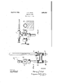
In the following description reference will be made to the accompanying drawings forming part hereof, and in which- Figure 1 is an elevational view partly in section, and
Fig. 2 is a sectional view taken generally on the line 2-2 of Fig. 1.
In general, 1 indicates a liquid system of which the details are not important except that there is a valve 2 for admitting and exeluding liquid from the source of supply 3 to the system 1. There is a U-tube of which as one leg 4 is provided with a graduated scale and it is sealed and contains an air column adapted to be trapped by liquid in the lower portion of the U-tube and in the other leg 5 thereof and in the system. The U-tube is so provided with a valved duct 6 extending from the level of the zero graduation and from the interior of the leg 4i to the outside of the gauge. The valveis shown at 7 8 is a pet cock for draining the gauge and system.
In order for thegauge to be accurate the quantity of air trapped in the leg 4 must be appropriate. However, in use this condition does not obtain because frequently ad- 40 ditional air is added, for example, from the water in the system and gauge. To correct such defect and trap an appropriate volume of air at atmospheric pressure and at room temperature, the valve 2 is closed and the valves 7 and 8 are opened, thus the system is drained and is filled with atmospheric air at room temperature and pressure. Then the valve 8 is closed and the valve 2 opened and water fills the system and rises in the leg 4:, and after water starts torun through the duct 6, the valve 7 is closed. Thus there is trapped in the upper part of the leg at substantially the requisite quantity of air at atmospheric pressure and room temperature for adjusting the gauge to substantially the true values of the divisions of its graduated scale. The leg 4: is made of glass.
It will be obvious tothose skilled in the art to which the invention relates that modifications may be made in details of construction and arrangement and matters of mere form without departing from the spirit of the invention which is not limited to such matters or otherwise than the prior art and the appended claim may require.
I claim: a
In a pressure gauge for liquid systems the combination of a U-tube of which one leg is provided with a graduated scale and is sealed and contains an air column adapted to be trapped by liquid in the lower portion of the U-tube and in the other leg thereof and in the system, a valved duct extending from the level of the zero graduation and from the interior of the first mentioned leg to the outside of the gauge, means for draining the gauge and system, and means for excluding liquid from and admitting it to the system.
HARRY C. COLE.
Priority Applications (1)
| Application Number | Priority Date | Filing Date | Title |
|---|---|---|---|
| US549131A US1854781A (en) | 1931-07-07 | 1931-07-07 | Pressure gauge |
Applications Claiming Priority (1)
| Application Number | Priority Date | Filing Date | Title |
|---|---|---|---|
| US549131A US1854781A (en) | 1931-07-07 | 1931-07-07 | Pressure gauge |
Publications (1)
| Publication Number | Publication Date |
|---|---|
| US1854781A true US1854781A (en) | 1932-04-19 |
Family
ID=24191796
Family Applications (1)
| Application Number | Title | Priority Date | Filing Date |
|---|---|---|---|
| US549131A Expired - Lifetime US1854781A (en) | 1931-07-07 | 1931-07-07 | Pressure gauge |
Country Status (1)
| Country | Link |
|---|---|
| US (1) | US1854781A (en) |
-
1931
- 1931-07-07 US US549131A patent/US1854781A/en not_active Expired - Lifetime
Similar Documents
| Publication | Publication Date | Title |
|---|---|---|
| Rohwer | Evaporation from free water surfaces | |
| US1885926A (en) | Liquid measuring device | |
| US1854781A (en) | Pressure gauge | |
| US1980761A (en) | Flow meter | |
| US2153450A (en) | Single head meter | |
| US2041859A (en) | Liquid level indicator | |
| US1931274A (en) | Constant reading depth indicator and flow valve therefor | |
| US2688867A (en) | Specific gravity indicator | |
| US1143344A (en) | Automatic meter control. | |
| US1779353A (en) | Tender-cistern-water indicator | |
| US2301273A (en) | Compensating hydrometer | |
| US2158785A (en) | Liquid level indicator | |
| US3298234A (en) | Manometer | |
| US3054292A (en) | Remote indicating system for liquid tanks, especially fuel tanks | |
| US3120127A (en) | Manometer pressure indicator | |
| US2588875A (en) | Calibrated liquid level gauge | |
| US529365A (en) | Island | |
| US2148330A (en) | Automatic drain float | |
| SU6466A1 (en) | Liquid pressure gauge | |
| US2330983A (en) | Liquid level indicating means | |
| US1625420A (en) | Moisture guide for incubators | |
| US1670207A (en) | Apparatus for indicating the depth of liquids | |
| US1534206A (en) | Rate-of-climb indicator for aircraft | |
| US1805849A (en) | Liquid level indicating system | |
| US1706234A (en) | Hydrometer |