US185477A - Improvement in machines for hammering leather - Google Patents
Improvement in machines for hammering leather Download PDFInfo
- Publication number
- US185477A US185477A US185477DA US185477A US 185477 A US185477 A US 185477A US 185477D A US185477D A US 185477DA US 185477 A US185477 A US 185477A
- Authority
- US
- United States
- Prior art keywords
- hammers
- leather
- hammering
- machines
- improvement
- Prior art date
- Legal status (The legal status is an assumption and is not a legal conclusion. Google has not performed a legal analysis and makes no representation as to the accuracy of the status listed.)
- Expired - Lifetime
Links
- 239000010985 leather Substances 0.000 title description 16
- 230000000694 effects Effects 0.000 description 3
- 230000001105 regulatory effect Effects 0.000 description 3
- 230000003292 diminished effect Effects 0.000 description 1
- 239000000835 fiber Substances 0.000 description 1
- 238000007373 indentation Methods 0.000 description 1
- 150000002500 ions Chemical class 0.000 description 1
- 238000000034 method Methods 0.000 description 1
- 238000005096 rolling process Methods 0.000 description 1
- 239000004575 stone Substances 0.000 description 1
Images
Classifications
-
- C—CHEMISTRY; METALLURGY
- C14—SKINS; HIDES; PELTS; LEATHER
- C14B—MECHANICAL TREATMENT OR PROCESSING OF SKINS, HIDES OR LEATHER IN GENERAL; PELT-SHEARING MACHINES; INTESTINE-SPLITTING MACHINES
- C14B1/00—Manufacture of leather; Machines or devices therefor
- C14B1/38—Hammering leather
Definitions
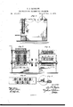
- Figure 1 represents a vertical section of a machine embracing my invention, the combination of hammers being in elevated positions;
- Fig. 2, a front elevation;
- Fig. 3, arear elevation, showing the hammer-guide fins;
- Fig. 4, a horizontal section, showing the combination of hammers;
- Fig. 5, a section showing the adjustment of tension device for the hammersprings.
- a suitable frame supports the anvil a, and the several operating parts of the machine.
- a multiplicity of hammers, b are arranged to form a combination, in which one series or group operates in front of the other, and breaks joints, the effect of which is to subject the leather passing over the anvil beneath them to a uniform hammering-surface of con-- siderable area, so that when working in the side the multiplicity of hammers gives the extended surface required, while being also adapted for hammering the sole or strip. This is a matter of great advantage.
- the hammers are, preferably, of oblong form with slightly-curved faces, to avoid any indentations of their ends in the surfaces of the leather, and their shanks c are supported in horizontal guide-plates d and e, to effect their vertical movement.
- the hammers are held from turning out of their proper position by finsf, which work in corresponding slots g, in a fixed back plate.
- the hammers are elevated and tripped by means of a suitablyformed cam, h, carried by a driving-shaft, 13, and acting upon the fins f, so as to lift all the hammers together; or the cam may have corrugations so as to lift the back hammers at one time and the front series in succession.
- the blows of the combination of hammers are made by springs j, suitably secured at the rear of the frame, and having their free ends bearing upon the tops of the hammershanks, which are guarded at their upper ends by rubber or leather cushions k, to limit the descent of the hammers, and prevent their striking and injuring the surface of the anvil. Above the guard-cushions, the shanks are screw-threaded, to receive each a thumb-nut, l, by which each hammer may be held to its proper adjustment.
- the blows of the hammers are regulated by a tension device, consisting of a cross-bar, m, with screws arranged to bear upon each spring and regulate its tension, to give the blow required. By turning the bar m upon its pivots all the screws may be put out of action at once, and the force of all the hammers correspondingly diminished, as the edge of the bar will then give tension upon the springs, as in Fig. 5.
- a suitable feeding-table is placed at the front of the machine, upon which to feed the stock under the hammers.
- the hammers may be in any number of groups, and the shaft which drives them is operated by power or crank.
- I claim- 1 A combination of hammers for hammering leather as it is moved upon and over the anvil, in which said hammers are operated in groups, to have a simultaneous and gaged descent upon the leather, as and for purpose herein set forth.
- a combination of hammers, arrangedto 1 break joints, one series operating in frontof the other, as the stock isfedj over the anvil. 3.
Landscapes
- Engineering & Computer Science (AREA)
- Manufacturing & Machinery (AREA)
- Mechanical Engineering (AREA)
- Chemical & Material Sciences (AREA)
- Organic Chemistry (AREA)
- Treatment And Processing Of Natural Fur Or Leather (AREA)
Description
C. D. 'BIGELOW.
MACHINES FOR HAMMERING LEA I HER.
No, 185,477, Patented Dec. 19,1876.
THE GRAPHIC CON.Y
UNITE]; STATES PATENT Qrrron.
CHARLES D. BIGELOW, OF NEW YORK, N. Y., ASSIGNOR TO THE BAY STATE SHOE AND LEATHER COMPANY.
IMPROVEMENT IN MACHINES FOR HAMMERING LEATHER.
Specification forming part of Letters Patent No. 185,477, dated December 19, 1876; application filed October 21, 1876.
To all whom it may concern:
Be it known that I, CHARLES D. BIGELOW, formerly of Brooklyn, but now of the city of New York, in the county of New York and State of New York, have invented certain new and useful Improvements in Machines for Hammering Leather; and I do hereby declare that the following is a full, clear, and exact description thereof, which will enable others skilled in the art to which it appertains to make and use the same, reference being had of leather has been done by the shoemaker.
with his hammer and lap-stone, and also by a single hammer in some machines; but this process is slow and expensive, besides difficult in getting the leather evenly hammered. Hammered leather, properly done, will finish finer on the bottom, and will burnish better and quicker on the edge than rolled leather.
I use a combination of hammers, arranged in a way to break joints, one series operating in front of the other, and thereby produc ing the best effect in evenly hammering the surface of the leather.
By this arrangement I leave the surface equally as smooth as when rolled, and of a more uniform solidity, and do not injure the fiber of the leather, doing better work, and equally as fast, as by rolling.
In the accompanying drawings, Figure 1 represents a vertical section of a machine embracing my invention, the combination of hammers being in elevated positions; Fig. 2, a front elevation; Fig. 3, arear elevation, showing the hammer-guide fins; Fig. 4, a horizontal section, showing the combination of hammers; and Fig. 5, a section showing the adjustment of tension device for the hammersprings.
A suitable frame supports the anvil a, and the several operating parts of the machine. A multiplicity of hammers, b, are arranged to form a combination, in which one series or group operates in front of the other, and breaks joints, the effect of which is to subject the leather passing over the anvil beneath them to a uniform hammering-surface of con-- siderable area, so that when working in the side the multiplicity of hammers gives the extended surface required, while being also adapted for hammering the sole or strip. This is a matter of great advantage.
The hammers are, preferably, of oblong form with slightly-curved faces, to avoid any indentations of their ends in the surfaces of the leather, and their shanks c are supported in horizontal guide-plates d and e, to effect their vertical movement. The hammers are held from turning out of their proper position by finsf, which work in corresponding slots g, in a fixed back plate. The hammers are elevated and tripped by means of a suitablyformed cam, h, carried by a driving-shaft, 13, and acting upon the fins f, so as to lift all the hammers together; or the cam may have corrugations so as to lift the back hammers at one time and the front series in succession.
The blows of the combination of hammers are made by springs j, suitably secured at the rear of the frame, and having their free ends bearing upon the tops of the hammershanks, which are guarded at their upper ends by rubber or leather cushions k, to limit the descent of the hammers, and prevent their striking and injuring the surface of the anvil. Above the guard-cushions, the shanks are screw-threaded, to receive each a thumb-nut, l, by which each hammer may be held to its proper adjustment. The blows of the hammers are regulated by a tension device, consisting of a cross-bar, m, with screws arranged to bear upon each spring and regulate its tension, to give the blow required. By turning the bar m upon its pivots all the screws may be put out of action at once, and the force of all the hammers correspondingly diminished, as the edge of the bar will then give tension upon the springs, as in Fig. 5.
[t is important thus to regulate the force of the blows for some kinds of leather; The upper. ends of the shanks are pointed, to enter cavities or perforations in the springs to keep them from rebounding. Weights, of course, may take the place of the springs, or the hammers themselves may be weighted.
A suitable feeding-table is placed at the front of the machine, upon which to feed the stock under the hammers. The hammers may be in any number of groups, and the shaft which drives them is operated by power or crank.
I have described the hammers as of oblong shape, but they may be of any desired form.
While the hammers are worked in groups simultaneously, they must also be operated with a gaged descent upon the surface of the leather; otherwise the design of my invention will fail. It will also be observed that the fins by which the hammers are elevated serve also as the means for preventing them from turning upon their carrying-stems.
I claim- 1. A combination of hammers for hammering leather as it is moved upon and over the anvil, in which said hammers are operated in groups, to have a simultaneous and gaged descent upon the leather, as and for purpose herein set forth.
2. A combination of hammers, arrangedto 1 break joints, one series operating in frontof the other, as the stock isfedj over the anvil. 3. A combination of hammers, arranged to break joints, as described, and having slightly-curved faces, for the purpose stated.
herein set forth.
5. The combinationofhammers, arrangedfli to operate as described, with the guard-cusb,
ions, the thumb-nuts, and the springs, sub- ?tantially as and for the purpose herein set orth.
6. The combinationlof hammers, arranged to operate as described,'with the springs,'tension-screws, and the turning-bar m, whereby the blow of each hammer is regulated bythe 1 screws, or all can be regulated at once by the turning-bar, for the purpose stated.
In testimony that I claimthe foregoing I; have affixed my signatureinpresence of two witnesses.
Witnesses: l
A. E. H. J oHNsoN, J. W. HAMmTo JoHNsoN.
OHARLEISD. BIGELOW. [fa
Publications (1)
| Publication Number | Publication Date |
|---|---|
| US185477A true US185477A (en) | 1876-12-19 |
Family
ID=2254883
Family Applications (1)
| Application Number | Title | Priority Date | Filing Date |
|---|---|---|---|
| US185477D Expired - Lifetime US185477A (en) | Improvement in machines for hammering leather |
Country Status (1)
| Country | Link |
|---|---|
| US (1) | US185477A (en) |
Cited By (2)
| Publication number | Priority date | Publication date | Assignee | Title |
|---|---|---|---|---|
| US2571149A (en) * | 1949-08-26 | 1951-10-16 | United Shoe Machinery Corp | Leather compacting and burnishing machine |
| US4718727A (en) * | 1984-05-29 | 1988-01-12 | Sheppard Michael B | Reversible seat cushion and backrest |
-
0
- US US185477D patent/US185477A/en not_active Expired - Lifetime
Cited By (2)
| Publication number | Priority date | Publication date | Assignee | Title |
|---|---|---|---|---|
| US2571149A (en) * | 1949-08-26 | 1951-10-16 | United Shoe Machinery Corp | Leather compacting and burnishing machine |
| US4718727A (en) * | 1984-05-29 | 1988-01-12 | Sheppard Michael B | Reversible seat cushion and backrest |
Similar Documents
| Publication | Publication Date | Title |
|---|---|---|
| US185477A (en) | Improvement in machines for hammering leather | |
| US786042A (en) | Dough-shaping machine. | |
| US415477A (en) | Cutting-press | |
| US8067A (en) | Horseshoe | |
| US84552A (en) | Improved knife-cleaner | |
| US316820A (en) | s pessenger | |
| US462646A (en) | Joseph e | |
| US363592A (en) | Third to solomon p | |
| US588422A (en) | gruber | |
| US103463A (en) | Improvement in machinery for scouring or dressing hides | |
| US356191A (en) | Leather-dressing machine | |
| US176313A (en) | Improvement in machines for flanging shoe-nail strips | |
| US118963A (en) | Improvement in machines for splitting wood | |
| US365430A (en) | Machine for extracting fibers | |
| US230450A (en) | tyrrell | |
| US835399A (en) | Leather-treating machine. | |
| US11368A (en) | X p peters | |
| US54034A (en) | Improved machine for combing bristles | |
| US1081447A (en) | Riveting-machine, multiple drive. | |
| US48186A (en) | Improved leather-dressing machine | |
| US7924A (en) | Machine for brepabing hides | |
| US8213A (en) | john stearns | |
| US231191A (en) | Machine for marking and punching holes in shoe-quarters | |
| US152847A (en) | Improvement in nailing-machines for boots and shoes | |
| US148085A (en) | Improvement in horseshoe-machines |