US1854767A - Reel for wire and the like - Google Patents
Reel for wire and the like Download PDFInfo
- Publication number
- US1854767A US1854767A US513672A US51367231A US1854767A US 1854767 A US1854767 A US 1854767A US 513672 A US513672 A US 513672A US 51367231 A US51367231 A US 51367231A US 1854767 A US1854767 A US 1854767A
- Authority
- US
- United States
- Prior art keywords
- barrel
- lugs
- reel
- flanges
- wire
- Prior art date
- Legal status (The legal status is an assumption and is not a legal conclusion. Google has not performed a legal analysis and makes no representation as to the accuracy of the status listed.)
- Expired - Lifetime
Links
- 238000010276 construction Methods 0.000 description 2
- 239000002184 metal Substances 0.000 description 2
- 239000011324 bead Substances 0.000 description 1
- 238000004519 manufacturing process Methods 0.000 description 1
Images
Classifications
-
- B—PERFORMING OPERATIONS; TRANSPORTING
- B65—CONVEYING; PACKING; STORING; HANDLING THIN OR FILAMENTARY MATERIAL
- B65H—HANDLING THIN OR FILAMENTARY MATERIAL, e.g. SHEETS, WEBS, CABLES
- B65H75/00—Storing webs, tapes, or filamentary material, e.g. on reels
- B65H75/02—Cores, formers, supports, or holders for coiled, wound, or folded material, e.g. reels, spindles, bobbins, cop tubes, cans, mandrels or chucks
- B65H75/04—Kinds or types
- B65H75/08—Kinds or types of circular or polygonal cross-section
- B65H75/14—Kinds or types of circular or polygonal cross-section with two end flanges
-
- B—PERFORMING OPERATIONS; TRANSPORTING
- B65—CONVEYING; PACKING; STORING; HANDLING THIN OR FILAMENTARY MATERIAL
- B65H—HANDLING THIN OR FILAMENTARY MATERIAL, e.g. SHEETS, WEBS, CABLES
- B65H2701/00—Handled material; Storage means
- B65H2701/50—Storage means for webs, tapes, or filamentary material
- B65H2701/51—Cores or reels characterised by the material
- B65H2701/511—Cores or reels characterised by the material essentially made of sheet material
- B65H2701/5114—Metal sheets
Definitions
- This invention relates to reels for wire and the like in which a pair of anges are attached to the ends of a tubular barrel. It has heretofore been proposed to' construct this g type of reel by forming lugs on the ends of a tubular barrel and folding the lugs over against the inner edges of a pair of annular fianges attached to the ends of the barrel.
- the barrel is formed at its ends with swages or circumferential ribs which abut against the inner sides of the iianges. I have found this construction of reel will not stand up to rough treatment, particularly when a large number of reels wound with wire are being transported by railways.
- the object of my invention is to provide an improved construction of reel of the type set forth which will be simple to manufacture and will stand up to rough treatment.
- annular flanges above and hereinafter, it is understood that I also contemplate fianges bounded by straight edges, oval edges or the like, and that if desired the barrel may be polygonal or oval in section instead of circular.
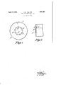
- Fig. l is a side elevation view
- Fig. 2 is a detail section to a larger scale on the line B-B of Fig. l.
- the barrel 1 is made from a strip of sheet metal bent to cylindrical form and having its ends soldered or otherwise united.
- Equi-distantly spaced lugs 2 are formed on the ends of the barrel l by removing portions from the longitudinal edges of the strip from which the barrel is made.
- the iianges 3 are made'of sheet metal cut to annular form, their apertures 4 being smaller in diameter than the diameter of the barrel l, for normal purposes this difference in diameter being about one inch.
- a number of slots 5 are pressed out of the fianges located so as to correspond and register with the lugs 2 on the ends of the barrel.
- the lugs 2 are passed through the slots 5 as a nice fit and are pressed over against the outer faces of the flanges towards their centres.
- the lugs 2 of the barrel may be pressed into the flanges so that they ⁇ become countersunk.
- a reel for wire a barrel and two substantially annular fianges, the barrel being greater in diameter than the inner diameter of the flanges, lugs at the ends of the barrel and slots formed in the ianges, the lugs being passed through said slots and pressed over against the outer faces of the anges, the said lugs being bent towards the centres of the anges, and the inner edges of the fianges being bent over against the free ends of the lugs, and circumferential ribs on said barrel abutting against the inner faces of the flanges.
Landscapes
- Storage Of Web-Like Or Filamentary Materials (AREA)
Description
April 19, 1932. A. w. SAULTER REEL FOR WIRE AND THE LIKE Filed Feb. 5, 1931 Patented Apr. 19, 1932 ALFRED WALTER SAULTER, OF ROTHERHITEE, LONDON, ENGLAND REEL FOR WIRE AND THE VLIKE Application led February 5, 1931, Serial No. 513,672, and in Great Britain February 11, 1930.
This invention relates to reels for wire and the like in which a pair of anges are attached to the ends of a tubular barrel. It has heretofore been proposed to' construct this g type of reel by forming lugs on the ends of a tubular barrel and folding the lugs over against the inner edges of a pair of annular fianges attached to the ends of the barrel. The barrel is formed at its ends with swages or circumferential ribs which abut against the inner sides of the iianges. I have found this construction of reel will not stand up to rough treatment, particularly when a large number of reels wound with wire are being transported by railways. The object of my invention is to provide an improved construction of reel of the type set forth which will be simple to manufacture and will stand up to rough treatment. In referring to annular flanges above and hereinafter, it is understood that I also contemplate fianges bounded by straight edges, oval edges or the like, and that if desired the barrel may be polygonal or oval in section instead of circular.
In order that my invention may be clearly understood and readily carried into effect, I have appended hereto a sheet of drawings illustrating embodiments thereof, and wherein,
Fig. l is a side elevation view, and
Fig. 2 is a detail section to a larger scale on the line B-B of Fig. l.
Referring to the drawings, the barrel 1 is made from a strip of sheet metal bent to cylindrical form and having its ends soldered or otherwise united. Equi-distantly spaced lugs 2 are formed on the ends of the barrel l by removing portions from the longitudinal edges of the strip from which the barrel is made. The iianges 3 are made'of sheet metal cut to annular form, their apertures 4 being smaller in diameter than the diameter of the barrel l, for normal purposes this difference in diameter being about one inch. A number of slots 5 are pressed out of the fianges located so as to correspond and register with the lugs 2 on the ends of the barrel. The lugs 2 are passed through the slots 5 as a nice fit and are pressed over against the outer faces of the flanges towards their centres.
The edges of the holes are pressed outwards against the outer faces of the flanges 3 so as to press against and overhang the free edges of the lugs 2. Y
Additional security can be obtained by forming a raised circumferential bead or swage 9 (see Fig. 2) round each end of the barrel l to abut against the inner faces of the flanges 3.
The lugs 2 of the barrel may be pressed into the flanges so that they `become countersunk.
What I claim is zl. In a reel for wire a barrel and two substantially annular flanges, the barrel being greater in diameter than the inner diameter of the ianges, lugs at the ends of the barrel and slots formed in the flanges, the lugs being passed through said slots and pressed over against the outer faces of the flanges, the said lugs being bent towards the centres of the flanges, and the inner edges of the flanges being bent over against the free ends of the lugs.
2. In a reel for wire a barrel and two substantially annular fianges, the barrel being greater in diameter than the inner diameter of the flanges, lugs at the ends of the barrel and slots formed in the ianges, the lugs being passed through said slots and pressed over against the outer faces of the anges, the said lugs being bent towards the centres of the anges, and the inner edges of the fianges being bent over against the free ends of the lugs, and circumferential ribs on said barrel abutting against the inner faces of the flanges.
In witness whereof I have signed this specication.
ALFRED WALTER SAULTER.
Applications Claiming Priority (1)
| Application Number | Priority Date | Filing Date | Title |
|---|---|---|---|
| GB4605/30A GB347348A (en) | 1930-02-11 | 1930-02-11 | Improvements in and connected with reels for wire and the like |
Publications (1)
| Publication Number | Publication Date |
|---|---|
| US1854767A true US1854767A (en) | 1932-04-19 |
Family
ID=9780316
Family Applications (1)
| Application Number | Title | Priority Date | Filing Date |
|---|---|---|---|
| US513672A Expired - Lifetime US1854767A (en) | 1930-02-11 | 1931-02-05 | Reel for wire and the like |
Country Status (2)
| Country | Link |
|---|---|
| US (1) | US1854767A (en) |
| GB (1) | GB347348A (en) |
Families Citing this family (2)
| Publication number | Priority date | Publication date | Assignee | Title |
|---|---|---|---|---|
| GB8425222D0 (en) * | 1984-10-05 | 1984-11-14 | Smiths Industries Plc | Reels |
| US4620676A (en) * | 1985-09-19 | 1986-11-04 | Manfred Missalla | Dismountable reel |
-
1930
- 1930-02-11 GB GB4605/30A patent/GB347348A/en not_active Expired
-
1931
- 1931-02-05 US US513672A patent/US1854767A/en not_active Expired - Lifetime
Also Published As
| Publication number | Publication date |
|---|---|
| GB347348A (en) | 1931-04-30 |
Similar Documents
| Publication | Publication Date | Title |
|---|---|---|
| US1854767A (en) | Reel for wire and the like | |
| US2023611A (en) | Pulley or idler | |
| US1800642A (en) | Method of making well screens | |
| US2122971A (en) | Lamp shade | |
| US1754541A (en) | Egg-case filler | |
| US1951151A (en) | Tape spool | |
| US1892356A (en) | Spool | |
| US1952873A (en) | Balanced spiral fabric | |
| US1451745A (en) | Reel | |
| US1454305A (en) | Corrugated roller | |
| US1509441A (en) | Reel for motion-picture films | |
| US868105A (en) | Cage for rolls in roller-bearings. | |
| US1677951A (en) | Spool | |
| US1782977A (en) | Metallic shade roller | |
| US1179073A (en) | Clip. | |
| US1715114A (en) | Cage for roller bearings | |
| US1991435A (en) | Metallic spool | |
| US1825866A (en) | Fishing reel | |
| US1879237A (en) | Production of lenticular elements on films | |
| US1409533A (en) | Film reel | |
| US1885137A (en) | Method of making pile wires | |
| US1999422A (en) | Steaming spool | |
| US1698463A (en) | Adjustable ring book | |
| AT117748B (en) | Winding drum for iron shutters. | |
| US1876939A (en) | Curtain roller construction |