US1854763A - Electroplating machine - Google Patents
Electroplating machine Download PDFInfo
- Publication number
- US1854763A US1854763A US452575A US45257530A US1854763A US 1854763 A US1854763 A US 1854763A US 452575 A US452575 A US 452575A US 45257530 A US45257530 A US 45257530A US 1854763 A US1854763 A US 1854763A
- Authority
- US
- United States
- Prior art keywords
- barrel
- container
- tumbling
- cathode
- rollers
- Prior art date
- Legal status (The legal status is an assumption and is not a legal conclusion. Google has not performed a legal analysis and makes no representation as to the accuracy of the status listed.)
- Expired - Lifetime
Links
- 238000009713 electroplating Methods 0.000 title description 22
- 239000003792 electrolyte Substances 0.000 description 18
- 230000008093 supporting effect Effects 0.000 description 17
- 230000007246 mechanism Effects 0.000 description 13
- 238000009413 insulation Methods 0.000 description 12
- 238000007747 plating Methods 0.000 description 12
- 230000002093 peripheral effect Effects 0.000 description 7
- 239000012774 insulation material Substances 0.000 description 5
- 238000010276 construction Methods 0.000 description 4
- 239000002184 metal Substances 0.000 description 4
- 229910052751 metal Inorganic materials 0.000 description 4
- 241001251094 Formica Species 0.000 description 3
- 230000009467 reduction Effects 0.000 description 3
- 239000002253 acid Substances 0.000 description 2
- 230000009471 action Effects 0.000 description 2
- 238000013019 agitation Methods 0.000 description 2
- 238000004140 cleaning Methods 0.000 description 2
- 238000006073 displacement reaction Methods 0.000 description 2
- 239000000463 material Substances 0.000 description 2
- 230000003014 reinforcing effect Effects 0.000 description 2
- 230000000284 resting effect Effects 0.000 description 2
- 229910001369 Brass Inorganic materials 0.000 description 1
- RYGMFSIKBFXOCR-UHFFFAOYSA-N Copper Chemical compound [Cu] RYGMFSIKBFXOCR-UHFFFAOYSA-N 0.000 description 1
- 239000003513 alkali Substances 0.000 description 1
- 230000000712 assembly Effects 0.000 description 1
- 238000000429 assembly Methods 0.000 description 1
- 230000015572 biosynthetic process Effects 0.000 description 1
- 239000010951 brass Substances 0.000 description 1
- 229910052802 copper Inorganic materials 0.000 description 1
- 239000010949 copper Substances 0.000 description 1
- 229940014144 folate Drugs 0.000 description 1
- OVBPIULPVIDEAO-LBPRGKRZSA-N folic acid Chemical compound C=1N=C2NC(N)=NC(=O)C2=NC=1CNC1=CC=C(C(=O)N[C@@H](CCC(O)=O)C(O)=O)C=C1 OVBPIULPVIDEAO-LBPRGKRZSA-N 0.000 description 1
- 235000019152 folic acid Nutrition 0.000 description 1
- 239000011724 folic acid Substances 0.000 description 1
- 238000007654 immersion Methods 0.000 description 1
- 208000017482 infantile neuronal ceroid lipofuscinosis Diseases 0.000 description 1
- 235000000396 iron Nutrition 0.000 description 1
- 238000000034 method Methods 0.000 description 1
- 230000003534 oscillatory effect Effects 0.000 description 1
- 230000008569 process Effects 0.000 description 1
- 230000002787 reinforcement Effects 0.000 description 1
- 230000000717 retained effect Effects 0.000 description 1
- 239000011435 rock Substances 0.000 description 1
Images


Classifications
-
- C—CHEMISTRY; METALLURGY
- C25—ELECTROLYTIC OR ELECTROPHORETIC PROCESSES; APPARATUS THEREFOR
- C25D—PROCESSES FOR THE ELECTROLYTIC OR ELECTROPHORETIC PRODUCTION OF COATINGS; ELECTROFORMING; APPARATUS THEREFOR
- C25D17/00—Constructional parts, or assemblies thereof, of cells for electrolytic coating
- C25D17/16—Apparatus for electrolytic coating of small objects in bulk
- C25D17/18—Apparatus for electrolytic coating of small objects in bulk having closed containers
- C25D17/20—Horizontal barrels
Definitions
- This invention relates to new and useful improvements in electroplating machines, the objects of the invention being the provision of a machine having a revoluble tumbling Jarrel operatively supported in the electrolyte container and adapted to be raised out of said container whereby the articles contained in said barrel can be readily and conveniently removed.
- Other objects of the invention are to provide a revoluble tumbling barrel movable into and out of the electrolyte container and and provided with electrical connections including switch blades, which latter are adapted to cooperate with stationary switch contacts whereby the electrical circuit is automatically completed through said switch blade and said switch contacts when said barrel is disposed in said container and whereby the electrical circuit is automatically opened when said barrel is raised from said container.
- Still further objects of the invention are to provide an open topped electrolyte container and a revoluble mounted tumbling barrel, which latter issuspended above and movable into and out of'said container, said barrel being provided with switch blades electrically connected with.
- the cathode elements disposed in said barrel'and said container being provided with switch contacts connected'to the electric circuit and adapted to be engaged by said switch blades when the barrel occupies position withins'aid contain er whereby saidcatliode elements are interposed in the electric circuit, said switch ladesbeing disengageable from, said switch contacts to interrupt the electric circuit when said barrel is raised from said container.
- Another object of the invention is. i so mount the cathode in the tumbling barrel that said cathode is freely suspended from 1930. Serial No. 452,575.
- Still another object of the invention is to V provide a tumbling barrel rovided with hollow trunnions by means 0 which said barrel is revolubly supported and to extend the electrical connections through said trunnion into said barrel and freely and detachably suspend from said connections a cathode element whereby said element remains in close contact with the articles contained in the barrel during the rotation of the latter and whereby said cathode element is readily detachable for cleaning and replacement purposes.
- Figure 2 is a horizontal cross section taken on line 22 of Figure 1.
- Figure 3 is an end elevational view.
- Figure 4 is a vertical cross section taken on line 4.4 of Figure 1.
- Figure 5 is an enlarged vertical cross section, partly broken away, taken on line 5-5 of Figure 1.
- Figure 6 is a transverse cross section trough the tumbling barrel. 4
- Figure 7 is an enlarged cross section taken on line 77 of Figure 6.
- Figure 8 is an enlarged fragmental cross section of the tumbling barrel.
- Figure 9 is an enlarged detail cross section taken through the trunnion of the tumbling barrel.
- FigurelO is an enlarged detail cross seciion taken on line 1010 of. Figure 5.
- Figure 11 is a vertical cross sectio'nfshowing a IUOdlfiGdIOIIll of my invention.
- the present invention relates to that type of electroplating machines wherein" a per fol-ate tumbling barrel is revolubly mounted and'is immersed in the electrolyte contained in a suitable container.
- Suitable power driven means is located in the container and serves to support and actuate said barrel, whereby the articles contained in the barrel are constantly agitated.
- Manually operable means is provided for lowering and raising said barrel intoand out of said container, and said barrel and said container are provided with cooperating switch contacts whereby the electrical circuit is automatically completed when the barrel is in position in said container and said electrical circuit is opened when the barrel occu ies raised po sition.
- 10 indicates an open top container or tank
- 11 indicates a tumbling barrel which-is flexibly mounted by means of chains 12 so that, it can be moved relatively to said tank.
- the container 10 which contains the electrolyte is substantially box-shaped in cross section and is open at the top so that 'the barrel 11 can be lowered into and raised from said container.
- the barrel 11 is polygonal in cross section and consists of perforate walls 14 which are attached by tie rods 15 to the end members 16. These end members are of circular shape and have attached to their edges by suitable fastening means 17 rings 18. Panels or walls 14 and ends 16 areformed of insulation material, such as formica, in order to weserve the insulated relation between the arrel and the articles contained therein. Rings 18 are formed of metal and the outer edges of said rings are substantially V-shaped in cross section, as indicated at 18. As said rings 18 and screws 17 are located exteriorly of the barrel and spaced a suitable distance from the walls thereof, they do not affect the insulation of the articles contained in the barrel. Tie rods 15 are enclosed and insulated by insulation sleeves 19 which extend the full length between end members 16.
- the walls 14 can be secured together in any suitable manner. As illustrated herein certain of the walls are provided with flanges 14 which overlap the edges of the adjacent walls and these flanges and the edges of such adjacent walls are provided with threaded openings in which are screw-seated screws 20, also formed of insulation material. of the walls, such as 14*, extends outwardly through an opening 20 formed mom of the end members 16, and is slidable outwardly so as to provide access to the barrel.
- the flanges 14 of the adjacent walls and auxillary flanges 14 located in spaced relation with flanges 14 form the runways between which said slidable wall 14" operates.
- Barrel 11 is supported by arms 21 located in spaced relation with the ends of the barrel.
- the lower ends of arms 21 have secured thereto sleeves 22 and revolubly mounted in each sleeve is a hollow trunnion 24, one end of which is screw-seated in threaded opening formed axially in each end member 16.
- the outer end of trunnion 24 projects a suitable distance beyond each sleeve 22 and has secured thereon a collar 25 which prevents the disengagement of the sleeve and the trunnion.
- Arms 21 extend radially a suitable distance from barrel 11 and the outer ends of said arms are tied together by a rod 26 and nuts 27, as clearly shown in Figures 1 and 3.
- the lower end of each chain 12 is secured to this ring and the upper ends of said chains are secured to a shaft 31, by means of screws 32, which shaft is disposed horizontally a suitable distance above container 10.
- the ends of this shaft are journaled in bearings 34 formed in the upper ends of uprights 35. Said uprights extend upwardly from the ends of container 10 and are secured to said ends, as indicated at 36.
- One end of shaft 31 has attached thereto a collar 37 and the other end of said shaft has fixed thereto a sprocket wheel 38 over which operates a sprocket chain 39.
- a small sprocket wheel 40 is arranged on one of the supports 35 a suitable distance below sprocket wheel 38 and is engaged by sprocket chain 39.
- a handle 41 is fixed to said sprocket wheel and provides for manual operation of said sprocket wheel whereby said shaft 31 may be actuated to raise or lower said barrel.
- a ratchet wheel 42 is conjoined to small sprocket wheel 40 and cooperating with said ratchet wheel is a pawl 44 pivotally mounted on one of the supports 35 at 45, whereby barrel 11 can be retained in raised position by means of said ratchet wheel 42 and pawlr44'.
- grooved wheels 46 which are arranged in pairs adjacent to each end-of the container and are adapted to receive therebetween the.
- Shafts 47 are power-driven, thereby causing, throughfrictional engagement with rollers 46, rotationof barrel 11 and the consequent agitation of the plating load.
- the actuation of said shafts is effected by means of sprocket wheels 55 secured to shafts 47 and a sprocket chain 56 operating over said sprocket wheels and over a sprocket wheel 5 which latter is fixed to an actuating shaft 58 of a suitable reduction gearing (not shown).
- This reduction gearing is enclosed in a housing 59 and is supported upon a bracket 60 which is secured to and extends from one of the end walls of container 10.
- the shaft 58 extends outwardly from said easing into a housing 61 which latter is secured to and extends upwardly from the container and encloses the sprocket wheel 57 and the upper portionof chain 56.
- an adjustable idler 62 is journaled at 64 and engages the chain 56 at a oint between sprocket wheel 57 and one of t e sprocket wheels 56.
- the reduction gearing is adapted to be operatively connected b a shaft 58, either directly or by a belt drive, to a suitable motor (not shown).
- shafts 47 are driven at the desired speed and in the same direction such as indicated by arrows in Figure 5.
- Wheels or rollers 46 being fixed to the shafts are actuated therewith and through their friction engagement with the metal tires or rims 18 of the ends 16 of the tumbling barrel 11 cause the actuation of the latter and the consequent agitation of tumbling of the plating load contained in said barrel.
- each roller 46 preferably the outer side, is provided with an annular flange 46 which is inclined toward the grooved portion of the roller, thereby assistin in centering the barto] in supporting position in the container.
- This flange 46" extends a suitable distance outwardly so as to prevent accidental displacement of the barrel to either side of the roller 46. Any excessive movement of the barrel longitudinally in the container beyond the flan es 46 is prevented by the trunnion assemblies of the barrel and the end walls of the container.
- each tubular member 65 Extending through each trunnion is a tubular member 65, preferably formed of suitable insulation material such as formica.
- the inner end of each tubular member 65 extends into the barrel past the innerend of the threaded end of trunnion 24 and has secured thereto a collar 66 by means of a set screw 67. This collar prevents withdrawal of the tubular member.
- the outer end of said tubuar member extends beyond the outer end of trunnion 24 and is screw-seated into an insulation block 68 and communicates with a chamber 69. The opposite end of this chamber is closed by a plug 70 which is screw-seated in position.
- tubular member 65 Extending through tubular member 65 is a rod 71 the inner end of which projects into the barrel a suitable distance beyond the inner end of said tubular member 65.
- a cap 72 of insulation material is detachably secured to the end of the projecting portion of rod 71.
- An arm 74 is freely mounted on said projecting portion and hangsdownwardly therefrom. The distance between the inner end of tubular member 65 and cap 72 is substantially greater than the width of the up- -per end of said arm so that the latter is free to slide on rod 71 as shown in Figure 9.
- the lower end of arm 74 is bifurcated as in-' dicated at 74 and pivotally mounted between said bifurcated portions, by means of a screw 75, is the apertured end of a cathode element 76.
- the lower portion of this cathode element is disposedhorizontally at right angle to arm 74 as indicated at 76 and is of substantial length in order to permit said cathode element to enter into close contact with the load or articles contained in the barrel.
- the cathode element is freely suspended within the barrel and is free to oscillate about the axis of rotation.
- rod 71 extends into chamber 69 of block 68 and is provided with a threaded opening into which is screw-seated the threaded end 77 of a connector 78.
- This connector extends upwardly and outwardly from block 68 and is enclosed by a tubular insulation member 79, the lower end of which is threaded and screw-seated in block 68 as indicated at 7 9.
- a member 80 of insulation material is arranged in chamber 69 to each side of the apertured end of rod 71 and is provided with threaded openings for the reception of the threaded end 77.
- connector 78 and rod 71 are rigidly secured togather and are enclosed, respectively, by tubular members 79 and 65.
- trunnions 24 operate within bearings 22 and revolve about the tubular member 65.
- Connector 78 and tubular member 79 extend upwardly in spaced relation with arms 21 and terminate a suitable distance below the upper ends thereof as shown in Figure 3.
- the upper end of each connector 78 is connected to the inner portion of a switch blade 81 which latter is fixed to the respective arm and insulated therefrom.
- Switch blades 81 are arranged substantially at right angles to arms 21 and extend rearwardly and are adapted to engage stationary switch contacts 82. These contacts are arranged inpairs and each pair is supported by a bracket 84 which is fixed to and insulated from the rearwardly projecting flange 52 of container 10 as indicated at 85.
- Each bracket 84 is provided with a depending extension 84" to which are connected, by means of screws 85, the ends of a bus bar 86.
- a terminal 87 of an electrical connection 88 is connected to said bus bar 86 thereby completing the negative or cathode side of the electric circuit.
- a longitudinally disposed rod 89 is arranged to each side of the container in spaced relation with the side walls thereof, as shown in Figure 4.
- These rods which may be of I brass or copper, have their ends seated in the end walls of'the container and have one of their ends extending outwardly as indicated at 89. These ends are connected together by a bus bar 90 and mounted on said bus bar is a terminal 91 of the ositive electric connection 92. This provides the positive or anode side of the circuit.
- the anode elements 94 are suspended from rods 89, as indicated in dotted lines in Figures 2 and 4. These anode elements are immersed in the electrolyte and the electrolyte completes the circuit between the load or articles to be plated and said anode elements.
- the load being placed in the tumbling barrel is in electrical con tact with the cathode elements located therein and as it is "tumbled in said barrel receives the electrical deposit.
- the electrical connections of the barrel are located on the rear side of the apparatus, thereby leaving the front side thereof free of all projections and electrical connections, facilitating the loading and unloading operations.
- Arm 74 is detachably mounted on rod 71 so that it and the element 76 can be removed for stripping or cleaning purposes.
- Rod 71 is formed of metal but cap 72 is made of nonconducting material, such as formica, and therefore is not susceptible to the electric deposit action and is not effected by the plating process so that no difiiculty will be ex perienced in detaching it from rod 71 when it is desired to remove arm 74:
- Connector 78 and rod 71 which connect the cathode element 76 with the electric circuit are enclosed and insulated throughout their entire lengths so that there is no danger of short-circuiting.
- Arm 74 dangles freely from rod 71 and the cathode element 76 is always free to follow the tumbling action of the plating load or articles contained in the barrel when the latter is actuated.
- the clearance provided on rod 71 between the upper end of arm 74 and the adjacent surfaces permits sliding movement of said arm when necessary.
- the Windlass mechanism is adapted to support the barrel in raised position by means of ratchet wheel 42 and pawl 44 and the raised position of the barrel may be adjusted as desired by means of said wheel and said pawl.
- Arms 21 and connectors 78 and parts associated therewith are inclined rearwardly from vertical planes and when barrel 11 is in resting position'in container 10 and chains 12 are slackened, said arms 21 and connectors 78 and associated parts are permitted to rock or gravitate rearwardly, thereby automatically causing switch blades 81 to enter into engagement with contacts 82.
- shaft 31 is actuated to wind chains 12 thereupon the arms 21 are rocked forwardly by said chains immediately before the raising operation of the barrel, thereby causing disengagement of blades 81 from contacts 82 and the consequent disengagement of the barrel from the electric circuit.
- the driving mechanism for the barrel may be in operation before the immersion of the barrel in the container or it may be set in operation after the barrel has been placed in position.
- the traction chain 56 runs on four sprockets, including an idler 62 which is adjustable.
- the barrel when lowered into container 10 drops automatically into proper position due to the V-shape formation of the tires or rims 18 and to the V-shaped grooves on rollers 46.
- the friction drive arrangement disclosed in Figures 1 to 6 is especially suited for use wherein alkali solution is used as electrolyte.
- a gear drive such as shown in Figure 11, is preferable.
- a rim gear 95 is substituted for me- 26 rollers and shafts and the chain drive.
- the hubs 96 of the barrel 97 rest on suitable su ports 98 disposed within the tank near eac end thereof.
- a small idler 99 is operatively disposed above the cylinder or plating barrel, and meshes with gear 95.
- a large 1dler 100 also operatively mounted above the barrel meshes with idler 99 and is adapted to mesh, when the cylinder occupies immersed position, with a gear 101. This gear is fixed to shaft 102 which is an extension of the actuating shaft 58.
- the barrel is movable in a vertical plane so that a minimum space is required for the re ceptlon of the barrel in the electrolyte contamer.
- the plating load contained in the barrel is brought in close proximity to the anode elements contained in the container, thereby provlding economic construction and efiiclent operation.
- the cathode elements are freely suspended with in the barrel and are permitted longitudina ly as well as dangling or oscillatory movement so that they can adapt themselves readily to the disposition of the plating load. They can be readily replaced and there are no other parts located within the barrel which are apt to become plated and retard the removal of the cathode elements.
- the driving mechanism is so arranged that the barrel can be readily moved into and out of the container simply by the raising of the barrel, and the electrical connections are simultaneously connected and disconnected by the movement of the barrel.
- the construction of the tumbling barrel is such that the plating load is held completely insulated from all'metal parts with the exception of the cathode elements.
- the peripheral walls of the barrel are perforated to permit the electrolyte to circulate freely therethrough.
- An electroplating machine comprising an open top electrolyte container, a tumbling barrel provided with peripheral tracks, fiexlble connections for supporting said barrel in raised position out of said container and operable to lower said barrel thereinto, and motor-driven mechanism in said container for engaging and revolubly supporting said barrel when in lowered position within said container.
- An electroplating machine comprising in combination an open top container, a revoluble tumbling barrel provided with peripheral tracks, an arm arranged adjacent to each end of said barrel and having its lower end revolubly attached thereto, a windlass mechanism connected to the upper ends of said arms whereby said barrel can be raised and lowered relatively to said container, and means in said container for engaging said tracks and revolubly and operatively sup porting said barrel therein.
- An electroplating machine comprising in combination an open top electrolyte container, a revoluble tumbling barrel provided with axially extending trunnions and annularly disposed tracks, a pair of arms having their lower ends revolubly engaging said trunnions, a Windlass mechanism 0 eratively connected to the upper ends of sai arms for raising said barrel and supporting it in raised position, rollers revolubly mounted in said container for engaging said tracks and revolubly sup orting said barrel in lowered position witl iin said container, and means for driving said rollers and actuating said barrel.
- An electroplating machine comprising an open top electrolyte container, a revoluble tumbling barrel provided with annular tracks and adapted to receive the plating load, means in said container for engaging said tracks and revolubly supporting said barrel therein, Windlass mechanism for raising said barrel out of said container and supporting it in raised position, and motordrlven means located within said container and adapted to be engaged by said annular tracks and revolubly support said barrel within said container.
- An electroplating machine comprising in combination an open top electrolyte container, a revoluble tumbling barrel adapted to receive the plating load, said barrel being provided at each end with a hollow trunnion and having its peripheral wall provided with annular tra'cks, an arm arranged adjacent to each end of said barrel and having its lower end engaging the corresponding trunnion and revolubly supporting said barrel, means in said container and including rollers for engaging said annular tracks and revolubly sup orting said barrel in sald container, winslass means connected to the upper ends of said arms for raising said barrel out of said container and supporting it in raised position, motor-driven means for actuating said supporting means stationary, switch contacts on said container and connected to one side of the main lines, a switch blade carried by each arm and adapted to engage said switch contacts when said barrel occupies lowered position and adapted to become isengaged from said switch contacts when said barrel occupies raised osition, electrodes connected to said bla es, and electrodes supported Within
- An electroplating machine comprising in combination an open top electrolyte container, a revoluble tumbling barrel having hollow trunnions, and provided with annular tracks, an arm arranged adjacent to each end of said barrel and having its lower end in revoluble supporting enga ement with said trunnion, means revolu ly mounted wit hin said container and adapted to be engaged by said annular tracks for revolubly supporting said barrel therein, mechanism connected to said arms for raising and supporting said barrel above said container, a switch blade arranged on each arm, connectors extending into said barrel through said hollow trunnion, a cathode element loosely suspended from the inwardly projecting end of each connector, an electric connection from each switch blade to the respective connector, stationary switch contacts arranged on one side of said container and adapted to be engaged by said switch blades when said barrel occupies position within said container, horizontally disposed rodsarranged in said container in spaced relation with said barrel, anode elements suspended within said container from said rods, electrical
- An electroplating machine comprising in combination an electrolyte-container, revoluble supports arranged therein, a revoluble barrel having annular tracks adapted to rest upon said revoluble supports whereby said barrel receives revoluble motion when in said container, a Windlass mechanism for 55 supporting said barrel in raised position and operable to lower said barrel into said container to be revolubly supported by said supports, motor driven means for actuating said arrel when in lowered position, rods disposed in said container in spaced relation with said barrel for supportin suitable anode elements, said rods being e ectrically connected to one side of an electric circuit, connectors dis osed coaxially with said bar- 65 rel and exten ing thereinto, a cathode ele- Windlass ment freely suspended from the inner end of each connector and adapted to be engaged by the plating load arranged within said barrel, stationary switch contacts connected to the other side of the electric circuit, and 7 switch blades connected to said connectors and adapted to engage said
- An electroplating machine comprising in combination an electrolyte container, sup ports arranged therein and including revoluble rollers, a revoluble barrel having peripheral tracks adapted to rest upon and be engaged by said rollers thereby receiving therefrom revoluble motion, windless mechanism for supporting said barrel in raised position and operable to lower said barrel into said container, motor driven means for actuating said supports, anode rods arranged longitudinally in said container in spaced relation with said barrel, and electrically connected to the positive pole of an electric circuit, anode elements suspended from said rods and immersed in the electrolyte, cathode rods extending axially into the barrel and adapted to be operatively connected to the negative pole of a circuit when said barrel occupies lowered position and to be disconnected therefrom when said barrel occupies raised position, and cathode elements pivotally suspended from the inner ends of said cathode rods and slidably arranged thereon so as to be movable longitudinally as well as pivotally of the axis of rotation of
- a revoluble tumbling barrel adapted to receive a plating load, an open-ended hollow trunnion arranged axially in each end wall of said barrel, a supporting arm having its lower end formed tubular for revolubly supporting each trunnion, an insulation sleeve disposed within each trunnion and extending beyond the ends thereof, a cathode connector extending through each insulation sleeve and having its 115 inner end extended a suitable distance beyond said insulation sleeve, a cathode element pivotally suspended from said inner end and movable longitudinally thereof, a connector connected to the outer end of said cathode 120 connector, and insulation means including a hollow insulation block engaging the outer end of said insulation sleeve and enclosing the interconnected ends of said cathode connector and said electrical connection.
Landscapes
- Chemical & Material Sciences (AREA)
- Engineering & Computer Science (AREA)
- Chemical Kinetics & Catalysis (AREA)
- Electrochemistry (AREA)
- Materials Engineering (AREA)
- Metallurgy (AREA)
- Organic Chemistry (AREA)
- Electroplating Methods And Accessories (AREA)
Description
April 19, 1932. H, J RlCHARDs ET AL 1,854,763
ELECTROPLA'IING MACHINE Filed May 15, 1930 4 Sheets-Sheet l M F 1 41 J6 32 4/ J/ 3,7 7
April 19, 1932. H. J. RICHARDS ET AL ELECTROPLATI NG MACH INE Filed May 15, 1930 4 Sheets-Sheet w -&
y .1 Richards am 6. f/z'mfazz April 1932- H. J. RICHARDS ET AL 1,854,753
ELECTROPLATING MACHINE Filed May 15, 1950 4 Sheets-Sheet ."5
April 1932- HA .1. RICHARDS ET AL 1,854,763
ELECTROPLATING MACHINE Patented Apr. 19, 1932 UNITED STATES PATENT OFFICE HEDLEY J. RICHARD-S AND WILLIAM E. HIN'ION, OF ST. LOUIS, MISSOURI, ASSIGNORS TO LASALCO, INCL, OF ST. LOUIS, MISSOURI, A CORPORATION OF MISSOURI ELECTROPLATING MACHINE Application filed May 15,
This invention relates to new and useful improvements in electroplating machines, the objects of the invention being the provision of a machine having a revoluble tumbling Jarrel operatively supported in the electrolyte container and adapted to be raised out of said container whereby the articles contained in said barrel can be readily and conveniently removed.
v Other objects of the invention are to provide a revoluble tumbling barrel movable into and out of the electrolyte container and and provided with electrical connections including switch blades, which latter are adapted to cooperate with stationary switch contacts whereby the electrical circuit is automatically completed through said switch blade and said switch contacts when said barrel is disposed in said container and whereby the electrical circuit is automatically opened when said barrel is raised from said container.
Further objects of the invention are to provide a tumbling barrel revolubly mounte by means of hollow trunnions, there being suitable electrical connections extending 1nto said barrel through said trunnions and carrying freely cathode elements so that the latter remain in close contact with the articles disposed in said barrel.
' Still further objects of the invention are to provide an open topped electrolyte container and a revoluble mounted tumbling barrel, which latter issuspended above and movable into and out of'said container, said barrel being provided with switch blades electrically connected with. the cathode elements disposed in said barrel'and said container being provided with switch contacts connected'to the electric circuit and adapted to be engaged by said switch blades when the barrel occupies position withins'aid contain er whereby saidcatliode elements are interposed in the electric circuit, said switch ladesbeing disengageable from, said switch contacts to interrupt the electric circuit when said barrel is raised from said container.
Another object of the invention is. i so mount the cathode in the tumbling barrel that said cathode is freely suspended from 1930. Serial No. 452,575.
the axis of rotation thereof and is at all times in close contact with the articles contained in said barrel.
Still another object of the invention is to V provide a tumbling barrel rovided with hollow trunnions by means 0 which said barrel is revolubly supported and to extend the electrical connections through said trunnion into said barrel and freely and detachably suspend from said connections a cathode element whereby said element remains in close contact with the articles contained in the barrel during the rotation of the latter and whereby said cathode element is readily detachable for cleaning and replacement purposes.
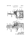
With these and other objects in view, my invention consists in certain novel features of construction and arrangement of parts, hereinafter more fully described and claimed, and illustrated in the accompanying drawings, in which 1 Figure 1 is a side elevational view of my improved electroplating machine.
Figure 2 is a horizontal cross section taken on line 22 of Figure 1.
Figure 3 is an end elevational view.
Figure 4 is a vertical cross section taken on line 4.4 of Figure 1.
Figure 5 is an enlarged vertical cross section, partly broken away, taken on line 5-5 of Figure 1. I
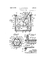
Figure 6 is a transverse cross section trough the tumbling barrel. 4
Figure 7 is an enlarged cross section taken on line 77 of Figure 6. Figure 8 is an enlarged fragmental cross section of the tumbling barrel.
Figure 9 is an enlarged detail cross section taken through the trunnion of the tumbling barrel.
FigurelO is an enlarged detail cross seciion taken on line 1010 of.Figure 5.
Figure 11 is a vertical cross sectio'nfshowing a IUOdlfiGdIOIIll of my invention.
The present invention relates to that type of electroplating machines wherein" a per fol-ate tumbling barrel is revolubly mounted and'is immersed in the electrolyte contained in a suitable container. "Suitable power driven means is located in the container and serves to support and actuate said barrel, whereby the articles contained in the barrel are constantly agitated. Manually operable means is provided for lowering and raising said barrel intoand out of said container, and said barrel and said container are provided with cooperating switch contacts whereby the electrical circuit is automatically completed when the barrel is in position in said container and said electrical circuit is opened when the barrel occu ies raised po sition. Thus the actuation o the barrel as well as the electric energy is de endent upon the operative position of sai barrel and neither can take place so long as the barrel is held in raised position.
Referring by numerals to the accompanying drawings, 10 indicates an open top container or tank, and 11 indicates a tumbling barrel which-is flexibly mounted by means of chains 12 so that, it can be moved relatively to said tank. r
The container 10 which contains the electrolyte is substantially box-shaped in cross section and is open at the top so that 'the barrel 11 can be lowered into and raised from said container.
The barrel 11 is polygonal in cross section and consists of perforate walls 14 which are attached by tie rods 15 to the end members 16. These end members are of circular shape and have attached to their edges by suitable fastening means 17 rings 18. Panels or walls 14 and ends 16 areformed of insulation material, such as formica, in order to weserve the insulated relation between the arrel and the articles contained therein. Rings 18 are formed of metal and the outer edges of said rings are substantially V-shaped in cross section, as indicated at 18. As said rings 18 and screws 17 are located exteriorly of the barrel and spaced a suitable distance from the walls thereof, they do not affect the insulation of the articles contained in the barrel. Tie rods 15 are enclosed and insulated by insulation sleeves 19 which extend the full length between end members 16.
The walls 14 can be secured together in any suitable manner. As illustrated herein certain of the walls are provided with flanges 14 which overlap the edges of the adjacent walls and these flanges and the edges of such adjacent walls are provided with threaded openings in which are screw-seated screws 20, also formed of insulation material. of the walls, such as 14*, extends outwardly through an opening 20 formed mom of the end members 16, and is slidable outwardly so as to provide access to the barrel. The flanges 14 of the adjacent walls and auxillary flanges 14 located in spaced relation with flanges 14 form the runways between which said slidable wall 14" operates.
Barrel 11 is supported by arms 21 located in spaced relation with the ends of the barrel. The lower ends of arms 21 have secured thereto sleeves 22 and revolubly mounted in each sleeve is a hollow trunnion 24, one end of which is screw-seated in threaded opening formed axially in each end member 16. The outer end of trunnion 24 projects a suitable distance beyond each sleeve 22 and has secured thereon a collar 25 which prevents the disengagement of the sleeve and the trunnion. Arms 21 extend radially a suitable distance from barrel 11 and the outer ends of said arms are tied together by a rod 26 and nuts 27, as clearly shown in Figures 1 and 3. Projecting inwardly from each arm 21, substantially halfway between the ends thereof, is a short extension 28, the outer end of which is provided with an opening 29 in which is secured a ring 30. The lower end of each chain 12 is secured to this ring and the upper ends of said chains are secured to a shaft 31, by means of screws 32, which shaft is disposed horizontally a suitable distance above container 10. The ends of this shaft are journaled in bearings 34 formed in the upper ends of uprights 35. Said uprights extend upwardly from the ends of container 10 and are secured to said ends, as indicated at 36. One end of shaft 31 has attached thereto a collar 37 and the other end of said shaft has fixed thereto a sprocket wheel 38 over which operates a sprocket chain 39. A small sprocket wheel 40 is arranged on one of the supports 35 a suitable distance below sprocket wheel 38 and is engaged by sprocket chain 39. A handle 41 is fixed to said sprocket wheel and provides for manual operation of said sprocket wheel whereby said shaft 31 may be actuated to raise or lower said barrel.
A ratchet wheel 42 is conjoined to small sprocket wheel 40 and cooperating with said ratchet wheel is a pawl 44 pivotally mounted on one of the supports 35 at 45, whereby barrel 11 can be retained in raised position by means of said ratchet wheel 42 and pawlr44'.
When the barrel 11 occupies position in the container, it is operatively supported therein by grooved wheels 46 which are arranged in pairs adjacent to each end-of the container and are adapted to receive therebetween the.
V-shaped edges of rings 18. The wheels or rollers 46 of each pair are spaced a suitable distance from each'other as shown in Figure 5 in order to support-therebetween the ends of barrel 11. These rollers are fixed to shafts 47 which are disposed longitudinally in the container and are journaled near their ends.
and is suspended within the container by means of bars 51, the lower ends of which are secured to said frame and which bars extend upwardly and have theirupper ends secured to angle irons 52, said anglesbeing attached to the upper edges of the side walls of the container and form reinforcing means therefor. The ends of the angles are secured to the transverse members 54 which form the reinforcement for the upper edges of the end walls of the container.
Thus it will 'be seen that the entire weight of the barrel and the supports therefor is transmitted by .bars 51 to the reinforcing means 52 and 54 and that the walls of the container are relieved of the strain.
This reduction gearing is enclosed in a housing 59 and is supported upon a bracket 60 which is secured to and extends from one of the end walls of container 10. The shaft 58 extends outwardly from said easing into a housing 61 which latter is secured to and extends upwardly from the container and encloses the sprocket wheel 57 and the upper portionof chain 56. Preferably an adjustable idler 62 is journaled at 64 and engages the chain 56 at a oint between sprocket wheel 57 and one of t e sprocket wheels 56.
The reduction gearing is adapted to be operatively connected b a shaft 58, either directly or by a belt drive, to a suitable motor (not shown). Thus by means of said sprocket wheel and chainconnections, shafts 47 are driven at the desired speed and in the same direction such as indicated by arrows in Figure 5. Wheels or rollers 46 being fixed to the shafts are actuated therewith and through their friction engagement with the metal tires or rims 18 of the ends 16 of the tumbling barrel 11 cause the actuation of the latter and the consequent agitation of tumbling of the plating load contained in said barrel.
In order to assist in bringing the barrel in proper position in the container and provide the necessary frictional contact between rollers 46 and rims 18, the sides 46 forming the annular grooves on rollers 46 are properly inclined so as to receive therebetween the inclined faces 18* of rims 18. Also one side of each roller 46, preferably the outer side, is provided with an annular flange 46 which is inclined toward the grooved portion of the roller, thereby assistin in centering the barto] in supporting position in the container.
This flange 46" extends a suitable distance outwardly so as to prevent accidental displacement of the barrel to either side of the roller 46. Any excessive movement of the barrel longitudinally in the container beyond the flan es 46 is prevented by the trunnion assemblies of the barrel and the end walls of the container.
As stated before, the trunnions 24 are formed hollow. Extending through each trunnion is a tubular member 65, preferably formed of suitable insulation material such as formica. The inner end of each tubular member 65 extends into the barrel past the innerend of the threaded end of trunnion 24 and has secured thereto a collar 66 by means of a set screw 67. This collar prevents withdrawal of the tubular member. The outer end of said tubuar member extends beyond the outer end of trunnion 24 and is screw-seated into an insulation block 68 and communicates with a chamber 69. The opposite end of this chamber is closed by a plug 70 which is screw-seated in position.
Extending through tubular member 65 is a rod 71 the inner end of which projects into the barrel a suitable distance beyond the inner end of said tubular member 65. A cap 72 of insulation material is detachably secured to the end of the projecting portion of rod 71. An arm 74 is freely mounted on said projecting portion and hangsdownwardly therefrom. The distance between the inner end of tubular member 65 and cap 72 is substantially greater than the width of the up- -per end of said arm so that the latter is free to slide on rod 71 as shown in Figure 9.
The lower end of arm 74 is bifurcated as in-' dicated at 74 and pivotally mounted between said bifurcated portions, by means of a screw 75, is the apertured end of a cathode element 76. The lower portion of this cathode element is disposedhorizontally at right angle to arm 74 as indicated at 76 and is of substantial length in order to permit said cathode element to enter into close contact with the load or articles contained in the barrel. Thus the cathode element is freely suspended within the barrel and is free to oscillate about the axis of rotation.
The outer end of rod 71 extends into chamber 69 of block 68 and is provided with a threaded opening into which is screw-seated the threaded end 77 of a connector 78. This connector extends upwardly and outwardly from block 68 and is enclosed bya tubular insulation member 79, the lower end of which is threaded and screw-seated in block 68 as indicated at 7 9. A member 80 of insulation material is arranged in chamber 69 to each side of the apertured end of rod 71 and is provided with threaded openings for the reception of the threaded end 77. Thus connector 78 and rod 71 are rigidly secured togather and are enclosed, respectively, by tubular members 79 and 65.
During the operation of the barrel, trunnions 24 operate within bearings 22 and revolve about the tubular member 65. Connector 78 and tubular member 79 extend upwardly in spaced relation with arms 21 and terminate a suitable distance below the upper ends thereof as shown in Figure 3. The upper end of each connector 78 is connected to the inner portion of a switch blade 81 which latter is fixed to the respective arm and insulated therefrom. Switch blades 81 are arranged substantially at right angles to arms 21 and extend rearwardly and are adapted to engage stationary switch contacts 82. These contacts are arranged inpairs and each pair is supported by a bracket 84 which is fixed to and insulated from the rearwardly projecting flange 52 of container 10 as indicated at 85. Each bracket 84 is provided with a depending extension 84" to which are connected, by means of screws 85, the ends of a bus bar 86. A terminal 87 of an electrical connection 88 is connected to said bus bar 86 thereby completing the negative or cathode side of the electric circuit.
A longitudinally disposed rod 89 is arranged to each side of the container in spaced relation with the side walls thereof, as shown in Figure 4. These rods, which may be of I brass or copper, have their ends seated in the end walls of'the container and have one of their ends extending outwardly as indicated at 89. These ends are connected together by a bus bar 90 and mounted on said bus bar is a terminal 91 of the ositive electric connection 92. This provides the positive or anode side of the circuit. The anode elements 94 are suspended from rods 89, as indicated in dotted lines in Figures 2 and 4. These anode elements are immersed in the electrolyte and the electrolyte completes the circuit between the load or articles to be plated and said anode elements.
The load being placed in the tumbling barrel is in electrical con tact with the cathode elements located therein and as it is "tumbled in said barrel receives the electrical deposit.
When the barrel is raised from the container by the Windlass mechanism (chain 12 and shaft 31) the switch blades 81 are disengaged from the switch contacts 82, thereby breaking the electric circuit and disengaging said tumblin barrel and the material contained therein from the main lines so that said barrel can be safely manipulated in dumping out the load.
The electrical connections of the barrel (bar 86 and switch members 81 and 82) are located on the rear side of the apparatus, thereby leaving the front side thereof free of all projections and electrical connections, facilitating the loading and unloading operations.
The Windlass mechanism is adapted to support the barrel in raised position by means of ratchet wheel 42 and pawl 44 and the raised position of the barrel may be adjusted as desired by means of said wheel and said pawl.
The driving mechanism for the barrel may be in operation before the immersion of the barrel in the container or it may be set in operation after the barrel has been placed in position.
The traction chain 56 runs on four sprockets, including an idler 62 which is adjustable. The barrel when lowered into container 10 drops automatically into proper position due to the V-shape formation of the tires or rims 18 and to the V-shaped grooves on rollers 46.
The friction drive arrangement disclosed in Figures 1 to 6 is especially suited for use wherein alkali solution is used as electrolyte.
When an acid solution is used, a gear drive, such as shown in Figure 11, is preferable. In this form a rim gear 95 is substituted for me- 26 rollers and shafts and the chain drive.
When the cylinder 97 is raised, idlers 99 and 100 are also raised and idler 100 is disengaged from gear 101 thereby disconnecting the driving mechanism from the cylinder 97. This cylinder can be raised or lowered when the actuating gear 101 is in operation. This arrangement eliminates the use of Only a mm mum amount of metallic parts, namely, the rim gear 97, is immersed in the electro- 'lyte and this gear can be especially made to render it acid resistant.
In our improved electroplating machine the barrel is movable in a vertical plane so that a minimum space is required for the re ceptlon of the barrel in the electrolyte contamer. Thus the plating load contained in the barrel is brought in close proximity to the anode elements contained in the container, thereby provlding economic construction and efiiclent operation.
As the cathode connections are admitted into the barrel through hollow trunnions, there are no rigid connectors arranged on the exterlor of the barrel and there are no exposed or movable connectors required. The cathode elements are freely suspended with in the barrel and are permitted longitudina ly as well as dangling or oscillatory movement so that they can adapt themselves readily to the disposition of the plating load. They can be readily replaced and there are no other parts located within the barrel which are apt to become plated and retard the removal of the cathode elements. The driving mechanism is so arranged that the barrel can be readily moved into and out of the container simply by the raising of the barrel, and the electrical connections are simultaneously connected and disconnected by the movement of the barrel.
The construction of the tumbling barrel is such that the plating load is held completely insulated from all'metal parts with the exception of the cathode elements. The peripheral walls of the barrel are perforated to permit the electrolyte to circulate freely therethrough.
While we have shown and described herein the preferred forms of our electroplating machine, it is obvious that various changes in the construction and arrangements of parts of our machine can be made and substituted for those herein shown.
We claim:
1. An electroplating machine comprising an open top electrolyte container, a tumbling barrel provided with peripheral tracks, fiexlble connections for supporting said barrel in raised position out of said container and operable to lower said barrel thereinto, and motor-driven mechanism in said container for engaging and revolubly supporting said barrel when in lowered position within said container.
2. An electroplating machine comprising in combination an open top container, a revoluble tumbling barrel provided with peripheral tracks, an arm arranged adjacent to each end of said barrel and having its lower end revolubly attached thereto, a windlass mechanism connected to the upper ends of said arms whereby said barrel can be raised and lowered relatively to said container, and means in said container for engaging said tracks and revolubly and operatively sup porting said barrel therein.
3. An electroplating machine comprising in combination an open top electrolyte container, a revoluble tumbling barrel provided with axially extending trunnions and annularly disposed tracks, a pair of arms having their lower ends revolubly engaging said trunnions, a Windlass mechanism 0 eratively connected to the upper ends of sai arms for raising said barrel and supporting it in raised position, rollers revolubly mounted in said container for engaging said tracks and revolubly sup orting said barrel in lowered position witl iin said container, and means for driving said rollers and actuating said barrel.
4. An electroplating machine comprising an open top electrolyte container, a revoluble tumbling barrel provided with annular tracks and adapted to receive the plating load, means in said container for engaging said tracks and revolubly supporting said barrel therein, Windlass mechanism for raising said barrel out of said container and supporting it in raised position, and motordrlven means located within said container and adapted to be engaged by said annular tracks and revolubly support said barrel within said container.
5. An electroplating machine comprising in combination an open top electrolyte container, a revoluble tumbling barrel adapted to receive the plating load, said barrel being provided at each end with a hollow trunnion and having its peripheral wall provided with annular tra'cks, an arm arranged adjacent to each end of said barrel and having its lower end engaging the corresponding trunnion and revolubly supporting said barrel, means in said container and including rollers for engaging said annular tracks and revolubly sup orting said barrel in sald container, winslass means connected to the upper ends of said arms for raising said barrel out of said container and supporting it in raised position, motor-driven means for actuating said supporting means stationary, switch contacts on said container and connected to one side of the main lines, a switch blade carried by each arm and adapted to engage said switch contacts when said barrel occupies lowered position and adapted to become isengaged from said switch contacts when said barrel occupies raised osition, electrodes connected to said bla es, and electrodes supported Within said container and immersed in said electrolyte in spaced relation with said container and electrically connected to the other side of the main lines.
6. An electroplating machine comprising in combination an open top electrolyte container, a revoluble tumbling barrel having hollow trunnions, and provided with annular tracks, an arm arranged adjacent to each end of said barrel and having its lower end in revoluble supporting enga ement with said trunnion, means revolu ly mounted wit hin said container and adapted to be engaged by said annular tracks for revolubly supporting said barrel therein, mechanism connected to said arms for raising and supporting said barrel above said container, a switch blade arranged on each arm, connectors extending into said barrel through said hollow trunnion,a cathode element loosely suspended from the inwardly projecting end of each connector, an electric connection from each switch blade to the respective connector, stationary switch contacts arranged on one side of said container and adapted to be engaged by said switch blades when said barrel occupies position within said container, horizontally disposed rodsarranged in said container in spaced relation with said barrel, anode elements suspended within said container from said rods, electrical connections connecting said rods to the positive pole of a generator, and electrical connections connecting said switch contacts to the negative side of a generator.
7 An electroplating machine comprising in combination an electrolyte-container, revoluble supports arranged therein, a revoluble barrel having annular tracks adapted to rest upon said revoluble supports whereby said barrel receives revoluble motion when in said container, a Windlass mechanism for 55 supporting said barrel in raised position and operable to lower said barrel into said container to be revolubly supported by said supports, motor driven means for actuating said arrel when in lowered position, rods disposed in said container in spaced relation with said barrel for supportin suitable anode elements, said rods being e ectrically connected to one side of an electric circuit, connectors dis osed coaxially with said bar- 65 rel and exten ing thereinto, a cathode ele- Windlass ment freely suspended from the inner end of each connector and adapted to be engaged by the plating load arranged within said barrel, stationary switch contacts connected to the other side of the electric circuit, and 7 switch blades connected to said connectors and adapted to engage said switch contacts when the barrel occupies lowered position, thereby completing the energizing circuit and adapted to be automatically disengaged from said switch blades when said barrel is raised from said container, thereby disconnecting said barrel from the electric circuit.
8. An electroplating machine comprising in combination an electrolyte container, sup ports arranged therein and including revoluble rollers, a revoluble barrel having peripheral tracks adapted to rest upon and be engaged by said rollers thereby receiving therefrom revoluble motion, windless mechanism for supporting said barrel in raised position and operable to lower said barrel into said container, motor driven means for actuating said supports, anode rods arranged longitudinally in said container in spaced relation with said barrel, and electrically connected to the positive pole of an electric circuit, anode elements suspended from said rods and immersed in the electrolyte, cathode rods extending axially into the barrel and adapted to be operatively connected to the negative pole of a circuit when said barrel occupies lowered position and to be disconnected therefrom when said barrel occupies raised position, and cathode elements pivotally suspended from the inner ends of said cathode rods and slidably arranged thereon so as to be movable longitudinally as well as pivotally of the axis of rotation of said barrel.
9. In an electroplating machine, a revoluble tumbling barrel adapted to receive a plating load, an open-ended hollow trunnion arranged axially in each end wall of said barrel, a supporting arm having its lower end formed tubular for revolubly supporting each trunnion, an insulation sleeve disposed within each trunnion and extending beyond the ends thereof, a cathode connector extending through each insulation sleeve and having its 115 inner end extended a suitable distance beyond said insulation sleeve, a cathode element pivotally suspended from said inner end and movable longitudinally thereof, a connector connected to the outer end of said cathode 120 connector, and insulation means including a hollow insulation block engaging the outer end of said insulation sleeve and enclosing the interconnected ends of said cathode connector and said electrical connection.
10. In an electroplating machine, the combination with a tumbling barrel, of a connector rod extending axially into said barrel through one of the walls thereof, and a cathode element pivotally suspended in said 133 barrel from the inner end of said rod and having its lower end bent at right angle and extending longitudinally parallel with the axis of said barrel.
11. In an electroplating machine of the class described, the combination with a tumbling barrel, of an insulation sleeve extending axially through each end wall of said barrel, a connector rod arranged in said sleeve and having its inner end extending a suitable distance into said barrel beyond the inner end of said insulation sleeve, an arm pivotally suspended from said inner end of said rod and movable longitudinally thereof, a ca detachably secured to the extreme end of sai rod to prevent displacement of said arm, and a cathode element attached to the free end of said arm and having its extreme portion disposed parallel with the axis of said barrel.
12. In an electroplating machine of the class described, the combination with an open-top container, of a plurality of rollers arranged in spaced relation, each of said rollers being provided with a V-shaped peripheral groove, a tumbling barrel provided with annular tracks V-shape in cross section and resting in the grooves of the respective rollers, and means for driving said rollers and imparting revoluble motion to said barrel.
13. In an electroplating machine of the class described, the combination with an open top container, of supports revolubly arranged therein and including a pair of horizontally disposed spaced shafts and a plurality of rollers fixed on said shafts, a tumbling barrel provided with peripheral tracks adapted to be revolubly supported by said rollers within said container, means for driving said shafts and impartin revoluble motion to said barrel, and win lass mechanism for raising said barrel from said container and disconnecting the driving connection thereof with said rollers.
In testimony whereof we hereunto afiix our signatures this "3rd day of May, 1930.
HEDLEY J. RICHARDS. WILLIAM E. HINTON.
Priority Applications (1)
| Application Number | Priority Date | Filing Date | Title |
|---|---|---|---|
| US452575A US1854763A (en) | 1930-05-15 | 1930-05-15 | Electroplating machine |
Applications Claiming Priority (1)
| Application Number | Priority Date | Filing Date | Title |
|---|---|---|---|
| US452575A US1854763A (en) | 1930-05-15 | 1930-05-15 | Electroplating machine |
Publications (1)
| Publication Number | Publication Date |
|---|---|
| US1854763A true US1854763A (en) | 1932-04-19 |
Family
ID=23797013
Family Applications (1)
| Application Number | Title | Priority Date | Filing Date |
|---|---|---|---|
| US452575A Expired - Lifetime US1854763A (en) | 1930-05-15 | 1930-05-15 | Electroplating machine |
Country Status (1)
| Country | Link |
|---|---|
| US (1) | US1854763A (en) |
Cited By (2)
| Publication number | Priority date | Publication date | Assignee | Title |
|---|---|---|---|---|
| US2967813A (en) * | 1958-08-29 | 1961-01-10 | Allen R Lindsay | Automatic marking device |
| US3479272A (en) * | 1966-08-09 | 1969-11-18 | Paul W Sandrock | Apparatus for plating,blackening,pickling,stripping and the like |
-
1930
- 1930-05-15 US US452575A patent/US1854763A/en not_active Expired - Lifetime
Cited By (2)
| Publication number | Priority date | Publication date | Assignee | Title |
|---|---|---|---|---|
| US2967813A (en) * | 1958-08-29 | 1961-01-10 | Allen R Lindsay | Automatic marking device |
| US3479272A (en) * | 1966-08-09 | 1969-11-18 | Paul W Sandrock | Apparatus for plating,blackening,pickling,stripping and the like |
Similar Documents
| Publication | Publication Date | Title |
|---|---|---|
| US1854763A (en) | Electroplating machine | |
| US1928949A (en) | Electroplating apparatus | |
| US2830946A (en) | Electroplating apparatus | |
| US2035633A (en) | Plating machine | |
| US1895622A (en) | Electroprocessing machine | |
| US4182669A (en) | Automatic electroplating apparatus | |
| CN210744967U (en) | Oil immersion antirust device for motor stator machining | |
| US1695795A (en) | Plating tank | |
| US3008893A (en) | Electroplating barrel assemblies | |
| US1509534A (en) | Electroplating machine | |
| US3421993A (en) | Electroplating barrel | |
| US1912400A (en) | Electroplating apparatus | |
| CN220793928U (en) | Intermediate frequency electric stove scraping device | |
| US4176015A (en) | Method for chromium electroplating of bars | |
| US2642392A (en) | Electroplating apparatus | |
| US1790289A (en) | Electroplating machine | |
| JP2648930B2 (en) | Hanging device for electroplating | |
| CN212247260U (en) | Barrel plating device | |
| US1936382A (en) | Electroplating apparatus | |
| US1563041A (en) | Electroplating apparatus | |
| KR100536133B1 (en) | Barrel type continuous plating device | |
| CN214032734U (en) | Barrel plating device capable of improving efficiency | |
| US2199487A (en) | Apparatus for electroplating metallic articles | |
| US1315785A (en) | Sylvania | |
| CN120480171A (en) | Slag beating device for aluminum electrolysis casting process |