US1854734A - Hose coupling - Google Patents
Hose coupling Download PDFInfo
- Publication number
- US1854734A US1854734A US223004A US22300427A US1854734A US 1854734 A US1854734 A US 1854734A US 223004 A US223004 A US 223004A US 22300427 A US22300427 A US 22300427A US 1854734 A US1854734 A US 1854734A
- Authority
- US
- United States
- Prior art keywords
- coupling
- heads
- rib
- head
- gaskets
- Prior art date
- Legal status (The legal status is an assumption and is not a legal conclusion. Google has not performed a legal analysis and makes no representation as to the accuracy of the status listed.)
- Expired - Lifetime
Links
- 230000008878 coupling Effects 0.000 title description 31
- 238000010168 coupling process Methods 0.000 title description 31
- 238000005859 coupling reaction Methods 0.000 title description 31
- NRUQNUIWEUZVLI-UHFFFAOYSA-O diethanolammonium nitrate Chemical compound [O-][N+]([O-])=O.OCC[NH2+]CCO NRUQNUIWEUZVLI-UHFFFAOYSA-O 0.000 description 3
Images
Classifications
-
- F—MECHANICAL ENGINEERING; LIGHTING; HEATING; WEAPONS; BLASTING
- F16—ENGINEERING ELEMENTS AND UNITS; GENERAL MEASURES FOR PRODUCING AND MAINTAINING EFFECTIVE FUNCTIONING OF MACHINES OR INSTALLATIONS; THERMAL INSULATION IN GENERAL
- F16L—PIPES; JOINTS OR FITTINGS FOR PIPES; SUPPORTS FOR PIPES, CABLES OR PROTECTIVE TUBING; MEANS FOR THERMAL INSULATION IN GENERAL
- F16L37/00—Couplings of the quick-acting type
- F16L37/24—Couplings of the quick-acting type in which the connection is made by inserting one member axially into the other and rotating it to a limited extent, e.g. with bayonet-action
- F16L37/256—Couplings of the quick-acting type in which the connection is made by inserting one member axially into the other and rotating it to a limited extent, e.g. with bayonet-action the coupling not being coaxial with the pipe
-
- F—MECHANICAL ENGINEERING; LIGHTING; HEATING; WEAPONS; BLASTING
- F16—ENGINEERING ELEMENTS AND UNITS; GENERAL MEASURES FOR PRODUCING AND MAINTAINING EFFECTIVE FUNCTIONING OF MACHINES OR INSTALLATIONS; THERMAL INSULATION IN GENERAL
- F16L—PIPES; JOINTS OR FITTINGS FOR PIPES; SUPPORTS FOR PIPES, CABLES OR PROTECTIVE TUBING; MEANS FOR THERMAL INSULATION IN GENERAL
- F16L37/00—Couplings of the quick-acting type
- F16L37/24—Couplings of the quick-acting type in which the connection is made by inserting one member axially into the other and rotating it to a limited extent, e.g. with bayonet-action
Definitions
- This invention relates to hose couplings such as are employed to connect flexible hose ends between cars of a train.
- the railway type of hand operated hose R coupling is provided with a lateral opening surrounded by an annular gasket and having interlocking means comprising an arcuate rib and an arcuate groove disposed concentr1- oally with the opening, the rib of one cou pling head being adapted to engage the groove of a counterparthead when the coupling heads are relatively rotated while in engagement, so that the heads are locked together thereby, and the gaskets of the coupling heads are pressed into engagement.
- the principal object of my invention is to provide a hose coupling of the above type in which means are provided for insuring that counterpart coupling heads can only be brought into engagement for coupling together, with the gaskets in axial alinement.
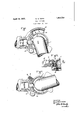
- Fig. 1 is a plan view or" two coupling heads applied the one to the other, and constructed in accordance with my invention, and showing the coupling heads in position before the locking rib of one head engages in the groove of the other head;
- Fig. 2 a plan View of the coupling heads in the fully coupled position;
- Fig. 3 a section on the line 33 of Fig. 1.
- the railway type of hose coupling comprises a body 1 having a lateral opening surrounded by a gasket 2 adapted to engage a corresponding Serial No. 223,004.
- the head is provided with an arcuate rib 3 i which is formed on a projecting flange 4 at one side of and concentric with the lateral opening.
- an angular arm 5 on the inner face of which is formed an arcuate groove 6, in which the rib 3 of a counterpart arm 5 is provided with a hook 7 and on the outer side of the body 1 is provided a curved rib or latch 8 concentric with the annular opening of the head and adapted to engage within the hook.
- the rib 8 is so positioned that when counterpart coupling heads are brought together for coupling up, as shown in Fig. 1, the rib 8 of one head must be in position to enter the hook 7 before the heads can be rotated to cause the rib 3 of one head to engage in the groove 6 of the other head.
- a hose coupling head having a lateral opening provided with a gasket, a curved rib, an angular arm having .a curved groove, the rib of the coupling head being adapted to engage the groove of counterpart coupling head, a hook carried by said arm, and a curved lug, the lug of the coupling head. being adapted to en age the hook of a counterpart coupling :ea cl in: adivance of the, engagement of the rib With the groove.
Landscapes
- Engineering & Computer Science (AREA)
- General Engineering & Computer Science (AREA)
- Mechanical Engineering (AREA)
- Quick-Acting Or Multi-Walled Pipe Joints (AREA)
Description
A ril 19, .1932. w. E. DEAN 1,854,734
HOSE COUPLING Filed Sept. so,' 1927 WNVENTOR WILLIAM EDI-IAN ATTORNEY Patented Apr. 19, 1932 UNITED STATES PATENT OFFICE WILLIAM E. DEAN, OF EDGEWOOD, PENN SYLVANIA, ASSIGNOR TO THE WESTINGHOUSE AIR BRAKE COMPANY, OF WVILMERDING, PENNSYLVANIA, A CORPORATION OF PENNSYLVANIA nosn COUPLING Application filed September 30, 1927.
This invention relates to hose couplings such as are employed to connect flexible hose ends between cars of a train.
The railway type of hand operated hose R coupling is provided with a lateral opening surrounded by an annular gasket and having interlocking means comprising an arcuate rib and an arcuate groove disposed concentr1- oally with the opening, the rib of one cou pling head being adapted to engage the groove of a counterparthead when the coupling heads are relatively rotated while in engagement, so that the heads are locked together thereby, and the gaskets of the coupling heads are pressed into engagement.
With a coupling of the above type, it is possible and sometimes happens that the coupling heads are brought together 1n such a way that the gaskets engage while out of axial alinement and then when the heads are relatively rotated to interlock the heads, the gaskets are distorted by the interlocking movement which brings the lateral openings into axial alinement. As a result, the gaskets are clamped together in the coupled position,
with the gaskets overlapped so that the area of the lateral opening is reduced and due to the distortion of the gaskets, leakage is liable to occur.
The principal object of my invention is to provide a hose coupling of the above type in which means are provided for insuring that counterpart coupling heads can only be brought into engagement for coupling together, with the gaskets in axial alinement.
In the accompanying drawings; Fig. 1 is a plan view or" two coupling heads applied the one to the other, and constructed in accordance with my invention, and showing the coupling heads in position before the locking rib of one head engages in the groove of the other head; Fig. 2 a plan View of the coupling heads in the fully coupled position; and Fig. 3 a section on the line 33 of Fig. 1.
As shown in the drawings, the railway type of hose coupling comprises a body 1 having a lateral opening surrounded by a gasket 2 adapted to engage a corresponding Serial No. 223,004.
gasket of a counterpart coupling, when the eouphng heads are interlocked.
In order to interlock the coupling heads,
the head is provided with an arcuate rib 3 i which is formed on a projecting flange 4 at one side of and concentric with the lateral opening. On the opposite side of the lateral opening is provided an angular arm 5, on the inner face of which is formed an arcuate groove 6, in which the rib 3 of a counterpart arm 5 is provided with a hook 7 and on the outer side of the body 1 is provided a curved rib or latch 8 concentric with the annular opening of the head and adapted to engage within the hook.
The rib 8 is so positioned that when counterpart coupling heads are brought together for coupling up, as shown in Fig. 1, the rib 8 of one head must be in position to enter the hook 7 before the heads can be rotated to cause the rib 3 of one head to engage in the groove 6 of the other head.
With the rib 8 in position to enter the hook 7 the gaskets 2 will be in axial alinement, so that whenthe coupling heads are then rotated to cause the ribs 3 to interlock with the grooves 6 of the coupling heads, there will be no distortion of the gaskets.
After the coupling heads have been rotated to the coupled position, as shown in Fig. 2, the rib 8 will have been moved out of engagement with the hook 7 so that if cars should be pulled apart, the coupling heads between the cars can separate, as in the usual hose coupling.
While one illustrative embodiment of the invention has been described in detail, it is not my intention to limit its scope to that embodiment or otherwise than by the terms of the appended claim.
Having now described my invention, what I claim as new and desire to secure by Letters Patent, is
A hose coupling head having a lateral opening provided with a gasket, a curved rib, an angular arm having .a curved groove, the rib of the coupling head being adapted to engage the groove of counterpart coupling head, a hook carried by said arm, and a curved lug, the lug of the coupling head. being adapted to en age the hook of a counterpart coupling :ea cl in: adivance of the, engagement of the rib With the groove.
In testimony whereof I have hereunto set my hand.
VWILLIAM E; DEAN;
Priority Applications (1)
| Application Number | Priority Date | Filing Date | Title |
|---|---|---|---|
| US223004A US1854734A (en) | 1927-09-30 | 1927-09-30 | Hose coupling |
Applications Claiming Priority (1)
| Application Number | Priority Date | Filing Date | Title |
|---|---|---|---|
| US223004A US1854734A (en) | 1927-09-30 | 1927-09-30 | Hose coupling |
Publications (1)
| Publication Number | Publication Date |
|---|---|
| US1854734A true US1854734A (en) | 1932-04-19 |
Family
ID=22834597
Family Applications (1)
| Application Number | Title | Priority Date | Filing Date |
|---|---|---|---|
| US223004A Expired - Lifetime US1854734A (en) | 1927-09-30 | 1927-09-30 | Hose coupling |
Country Status (1)
| Country | Link |
|---|---|
| US (1) | US1854734A (en) |
-
1927
- 1927-09-30 US US223004A patent/US1854734A/en not_active Expired - Lifetime
Similar Documents
| Publication | Publication Date | Title |
|---|---|---|
| US1505255A (en) | Hose clamp | |
| US8061715B2 (en) | Glad hand fitting and gasket for railroad car brake hose | |
| US1854734A (en) | Hose coupling | |
| US3381977A (en) | Train line service connection means | |
| US1903445A (en) | Hose and pipe coupling | |
| US1797423A (en) | Hose coupling | |
| US3731953A (en) | Automatic air hose connector | |
| US898214A (en) | Automatic pipe-coupling for railway-cars. | |
| US3680875A (en) | Air brake hose coupler gasket | |
| US1619464A (en) | Train-pipe coupling | |
| US1765576A (en) | Hose coupling | |
| US961699A (en) | Train-pipe coupling. | |
| US1558601A (en) | Hose coupling | |
| US744505A (en) | Coupling. | |
| US1458862A (en) | Air-hose coupling | |
| US950812A (en) | Interchange coupling device. | |
| US1988385A (en) | Flexible metal pipe connection | |
| US690130A (en) | Steam and air coupling. | |
| US587111A (en) | Railway hose-coupling | |
| US1093858A (en) | Car-coupling. | |
| US888189A (en) | Automatic train-pipe coupling. | |
| USRE12902E (en) | Air-hose coupling | |
| US1194074A (en) | Jossph sohcagliohb | |
| US1460364A (en) | Train-pipe connector | |
| US1720257A (en) | Automatic train-pipe connecter |