US1854729A - Compressor control device - Google Patents
Compressor control device Download PDFInfo
- Publication number
- US1854729A US1854729A US313219A US31321928A US1854729A US 1854729 A US1854729 A US 1854729A US 313219 A US313219 A US 313219A US 31321928 A US31321928 A US 31321928A US 1854729 A US1854729 A US 1854729A
- Authority
- US
- United States
- Prior art keywords
- compressor
- pressure
- governor
- control device
- compressor control
- Prior art date
- Legal status (The legal status is an assumption and is not a legal conclusion. Google has not performed a legal analysis and makes no representation as to the accuracy of the status listed.)
- Expired - Lifetime
Links
- 239000012530 fluid Substances 0.000 description 8
- 230000000694 effects Effects 0.000 description 3
- 238000009877 rendering Methods 0.000 description 1
Images
Classifications
-
- G—PHYSICS
- G05—CONTROLLING; REGULATING
- G05D—SYSTEMS FOR CONTROLLING OR REGULATING NON-ELECTRIC VARIABLES
- G05D16/00—Control of fluid pressure
- G05D16/20—Control of fluid pressure characterised by the use of electric means
- G05D16/2006—Control of fluid pressure characterised by the use of electric means with direct action of electric energy on controlling means
- G05D16/2066—Control of fluid pressure characterised by the use of electric means with direct action of electric energy on controlling means using controlling means acting on the pressure source
Definitions
- This invention relates to fluid compress ing apparatus, such as employed on railway trains and traction cars.
- a governor device On vehicles equipped with a fluid compressor, a governor device is provided which is adapted, upon a predetermined reduction in pressure in the main or storage reservoir, to effect the starting of the compressor. hen the compressor is thus started, it continues to operate until the main reservoir pressure has been increased to a predetermined maximum degree, at which time, the compressor governor operates to effect the stopping of the compressor.
- the apparatus shown in the drawing comprises an electric motor driven fluid compressor 1 adapted to compress fluid through a pipe 2 into a main or storage reservoir 3, a normal compressor governor device a, and an additional compressor governor device 5.
- Each governor device is shown diagrammatically as comprising a casing containing a piston 6, subject on one side to the pressure of fluid as supplied from the main reser voir 3 through pipe 7, and subject on the opposite side to the pressure of a spring'8.
- Each piston carries a stem 9 having secured thereto a contact member 10, adapted when the piston is in its inner position, to close: a circuit leading to the electric motor 11 which drives the compressor 1 and to open the circuit when the piston is. moved out.
- Contact finger 12 of the governor device 4 and contact finger 15 of the governor device 5 are connected to wire 16 leading to the motor 11, contact finger 13 is connected to a wire 17 leading to a contact 18 adapted to" the coil of which is in circuit with the cone trol circuit wire 26.
- the usual controller handle, indicated diagrammatically at 27, is in apower on position, as shown in full lines, the relay 25 is energized, and the movable contact member 19 is held in the position shown in the drawing, inwhich a circuit is established from wire 23 to wire 17 through engagement of contacts 24: and 18'with the contact member 19, while the contact 21 is out of engagemum and minimum pressure range as ordinarily employed.
- the controller handle is shifted toofl position, as shown in dotted lines, and the relay 25 is then deenergized, so that the contact member 19 is permitted to move downwardly so as to cause the contact 21 to engage the contact member 19 while the contact member 19 moves out of engagement with the contact 18'.
- a circuit is then established from wire 23 to wire 20 and the governor device 5 is thus connected up to control the supply. of current to the motor 11.
- the governor device '5 is adjusted so that the piston 6 will not move downwardly to close the motor cir 5 compressor .motor.
Landscapes
- Physics & Mathematics (AREA)
- Fluid Mechanics (AREA)
- General Physics & Mathematics (AREA)
- Engineering & Computer Science (AREA)
- Automation & Control Theory (AREA)
- Control Of Positive-Displacement Pumps (AREA)
Description
April 19, 1932. H BE K 1,854,729
CDMPRESSOR CONTROL DEVICE Filed Oct. 18, 1928 INVENTOR CARL H. BECK B W/IW% ATTORNEY Patented Apr. 19, 1932 UNITED STATES PATENT OFFICE CARL H. BECK, OF MONTCLAIR, NEW JERSEY, ASSIGNOR TO THE WESTINGHOUSE AIR BRAKE COMPANY, OF WILMERDING, PENNSYLVANIA, A. CORPORATION OF PENN-T.
SYLVANIA COMPRESSOR CONTROL DEVICE Application filed October 18, 1928. Serial No. 313,219.
This invention relates to fluid compress ing apparatus, such as employed on railway trains and traction cars.
On vehicles equipped with a fluid compressor, a governor device is provided which is adapted, upon a predetermined reduction in pressure in the main or storage reservoir, to effect the starting of the compressor. hen the compressor is thus started, it continues to operate until the main reservoir pressure has been increased to a predetermined maximum degree, at which time, the compressor governor operates to effect the stopping of the compressor.
It is often undesirable to have the compressor running while a vehicle is standing, since the running of the compressor is apt to'be noisy to such an extent as to be disagreeable and annoying, and the principal object of my invention is to provide automatic means for preventing the compressor from operating while a vehicle is standing, or unless the main reservoir pressure has been reduced to a very low degree. 7
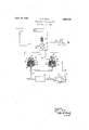
In the accompanying drawing, the single figure is a diagrammatic view of a fluid compressing apparatus embodying my invention.
The apparatus shown in the drawing comprises an electric motor driven fluid compressor 1 adapted to compress fluid through a pipe 2 into a main or storage reservoir 3, a normal compressor governor device a, and an additional compressor governor device 5. Each governor device is shown diagrammatically as comprising a casing containing a piston 6, subject on one side to the pressure of fluid as supplied from the main reser voir 3 through pipe 7, and subject on the opposite side to the pressure of a spring'8. Each piston carries a stem 9 having secured thereto a contact member 10, adapted when the piston is in its inner position, to close: a circuit leading to the electric motor 11 which drives the compressor 1 and to open the circuit when the piston is. moved out.
Contact finger 12 of the governor device 4: and contact finger 15 of the governor device 5 are connected to wire 16 leading to the motor 11, contact finger 13 is connected to a wire 17 leading to a contact 18 adapted to" the coil of which is in circuit with the cone trol circuit wire 26.
YVhen the usual controller handle, indicated diagrammatically at 27, is in apower on position, as shown in full lines, the relay 25 is energized, and the movable contact member 19 is held in the position shown in the drawing, inwhich a circuit is established from wire 23 to wire 17 through engagement of contacts 24: and 18'with the contact member 19, while the contact 21 is out of engagemum and minimum pressure range as ordinarily employed.
If the vehicle isbrought to a stop, the controller handle is shifted toofl position, as shown in dotted lines, and the relay 25 is then deenergized, so that the contact member 19 is permitted to move downwardly so as to cause the contact 21 to engage the contact member 19 while the contact member 19 moves out of engagement with the contact 18'. A circuit is then established from wire 23 to wire 20 and the governor device 5 is thus connected up to control the supply. of current to the motor 11. The governor device '5 is adjusted so that the piston 6 will not move downwardly to close the motor cir 5 compressor .motor.
cuit until the pressure in the reservoir 3 has been reduced to a relatively low degree, which is considerably lower than the pressure at which the governor device 4 operates to cut in the compressor motor, but which is sufficient to insure ample main reservoir pressure for operating the brakes to hold the vehicle while standing.
As a result, the usual high pressure governor is cut out while the car is standing and the compressor consequently is not operated while the car is standing, unless the main reservoir pressure should fall to the low degree at which the low pressure governor-5 is adjusted to operate- 7 I On the other hand, as soon as the controller is moved to a power on position so as to start the vehicle, tlieirelay 25.is energized so as to effect the cutting in of the high pressure governor and the consequent operation of the compressor to build up the main reservoir pressure to the usual maximum pressure carried.
While one illustrative embodiment of the invention has been described in detail, it is not my intention to limit. its scope to that embodiment or otherwise than by the terms of the appended claims.
Having now described my invention, what I claim as new and desire to secure by Letters Patent, is
1. The combination with a vehicle carried electric motor driven fluid compressor and device for controlling the circuit through which said governors supply electric current to the compressor motor and operative 1n a power-on position of the controller element for preventing one governor from acting and operative in ofi position ofrthe controller element for preventingthe othergovernor from acting.
3.. The combination with an electric motor driven fluid compressor, of two compressor governors, each adapted to control the opening and closing ofthe compressor motor circuit, a power controller element, and electrically controlled means operative in a ,powenoinposition ofthe controller element for rendering one governor. ineffective to control the compressor motor and in the OE posigovernors, each adapted to control the open-
Priority Applications (1)
| Application Number | Priority Date | Filing Date | Title |
|---|---|---|---|
| US313219A US1854729A (en) | 1928-10-18 | 1928-10-18 | Compressor control device |
Applications Claiming Priority (1)
| Application Number | Priority Date | Filing Date | Title |
|---|---|---|---|
| US313219A US1854729A (en) | 1928-10-18 | 1928-10-18 | Compressor control device |
Publications (1)
| Publication Number | Publication Date |
|---|---|
| US1854729A true US1854729A (en) | 1932-04-19 |
Family
ID=23214829
Family Applications (1)
| Application Number | Title | Priority Date | Filing Date |
|---|---|---|---|
| US313219A Expired - Lifetime US1854729A (en) | 1928-10-18 | 1928-10-18 | Compressor control device |
Country Status (1)
| Country | Link |
|---|---|
| US (1) | US1854729A (en) |
-
1928
- 1928-10-18 US US313219A patent/US1854729A/en not_active Expired - Lifetime
Similar Documents
| Publication | Publication Date | Title |
|---|---|---|
| US2295775A (en) | Compressor control apparatus | |
| US1854729A (en) | Compressor control device | |
| US1595755A (en) | Pneumatic control apparatus | |
| US2439474A (en) | Brake pressure responsive signal system | |
| US1991903A (en) | Electric brake mechanism | |
| US1864132A (en) | Compressor system | |
| US2038184A (en) | Compressor control device | |
| US2159781A (en) | Compressor control switch | |
| US2038185A (en) | Compressor governor | |
| US1961465A (en) | Control device for lifts | |
| US2257302A (en) | Electric brake system | |
| US2118403A (en) | Compressor control | |
| US1774138A (en) | Compressor control device | |
| US1947712A (en) | Compressor control means | |
| US2711230A (en) | Anti-wheel-slide safety control apparatus | |
| US1340861A (en) | Automatic railway safety control | |
| US1309787A (en) | Brake | |
| US1687107A (en) | Safety device for machine control | |
| US1387679A (en) | Pressure-release | |
| US2012746A (en) | Fluid pressure and electric brake interlock | |
| US1412819A (en) | Starting and unloading device for compressors | |
| US1506751A (en) | Liquid rheostat | |
| US1824048A (en) | Brake and power interlock | |
| USRE15343E (en) | Brake safety | |
| US2027865A (en) | Regenerative braking system |