US1854725A - Uncoupling valve and switch - Google Patents
Uncoupling valve and switch Download PDFInfo
- Publication number
- US1854725A US1854725A US467478A US46747830A US1854725A US 1854725 A US1854725 A US 1854725A US 467478 A US467478 A US 467478A US 46747830 A US46747830 A US 46747830A US 1854725 A US1854725 A US 1854725A
- Authority
- US
- United States
- Prior art keywords
- valve
- switch
- magnet
- bus
- chamber
- Prior art date
- Legal status (The legal status is an assumption and is not a legal conclusion. Google has not performed a legal analysis and makes no representation as to the accuracy of the status listed.)
- Expired - Lifetime
Links
Images
Classifications
-
- B—PERFORMING OPERATIONS; TRANSPORTING
- B61—RAILWAYS
- B61G—COUPLINGS; DRAUGHT AND BUFFING APPLIANCES
- B61G5/00—Couplings for special purposes not otherwise provided for
- B61G5/06—Couplings for special purposes not otherwise provided for for, or combined with, couplings or connectors for fluid conduits or electric cables
- B61G5/10—Couplings for special purposes not otherwise provided for for, or combined with, couplings or connectors for fluid conduits or electric cables for electric cables
Definitions
- This invention relates to devices for coupling cars and for connecting electric train line circuits between the cars of a train.
- 'An object of this invention is to provide means for controlling the bus line switch mechanism so that the bus switch will not operate each time the train passes over a gap in the trolley or third rail of sufficient length that the entire train loses contact with the power supply.
- Another object of the invention is, to provide an improved mechanism for controlling the bus line switch and for also controlling the uncoupling mechanism of the car coupler, v
- Another object of the invention is to providean improved automatic'car coupler of the character mentioned, which is simple in' construction, and reliable and exact in function under all conditions of servlce.
- the lnventlon also comprises certain new and useful improvements in the construction
- Figure 1 is a diagrammatic view, mostly in section, of
- Fig. 2 is a section taken on the line 22 of Fig. 1;
- Fig. 3 is anend view of a portion of the control mechanism shownin Fig. 1;
- Fig. 4 is a plan,part-ly in section of a modified form of control mechanism;
- Fig. 5 is a side elevation, partly in section of the structure shown in Fig. 4;
- Fig. 6 is a horizontal section-taken on the line 66 of Fig. 5.
- the equipment may comprise an automatic car, air and electric coupler device 6, a bus switch device 7, a magnet valve device 8 for operating the bus switch device 7, and a combined control valve and switch mechanism 9.
- the couplerdevice 6 may be of the type shown in United States Letters Patent No. 1,571,222 of February 2, 1926, and since the structure shown in the patent is well known in the art, only so much of the car coupler has been illustrated as to clearly understand the present invention.
- each coupler may comprise a hook-shaped projection 10 adapted to engage a corresponding inclined surface of a counterpart coupler and be rigidly clamped therewith by a locking lever 11.
- the car coupler also serves as a coupler for the fluid pressure pipes, such as the main reservoir pipe 12 and the brake pipe 13.
- the fluidpressure conduits are arranged in vertical alinement, and therefore the brake pipe connection through the coupler is omitted.
- v The conduit through the coupler for the main reservoir line is controlled by a tappet valve 14 which is unseated at the final part of the coupling movement.
- a brake pipe closing valve 15 is interposed in the brake pipe 13' and is adapted to be operated by a piston 16, the parts being contained in a casing 17 Fluid under pressure for operating piston 16 maybe supplied through.
- a'pipe 18, provided with a ball check valve 19, and leading from the combined control valve'and switch mechanism 9,.said'niechanism being operated in a manner to be hereinafter described to to engage the member 24 is a pair of contact fingers 25 and 26.
- a cylinder 27 is formed in the casing of the switch mechanism 7, andmounted in said cylinder is a piston 28 havinga piston stem 29.
- the outer'end of the stem 29 extends into a spring chamber 30 containing a coil spring 31.
- Said spring engages a member 32 secured to the stem 29 and tends to move the stem towards the left.
- An arm 33 is fixed to the squared end of shaft 23 and said arm is forked to engage over a flattened section of the stem 29.
- a pin 34 extends out from the flattened portion of the stem and engages in slot 35 in the arm 33.
- the spring finger 26 is secured to a terminal member 36 fixed to a block 37 formedfrom suitable insulating material, the end of the branched sect-ion of the bus wire 21 being also secured to the terminal member 36.
- the spring finger 25 is secured to a terminal member 38 which is also fixed to the block 37, the end of the main bus wire 21 being also secured to the terminal member 38.
- the magnet valve device 8 may comprise a magnet 39 and a double beat valve 40 adapted to be operated by said magnet.
- the double beat valve 40 is mounted in a chamber 41'connected tothe piston chamber 42 of the bus switch device 7 by a pipe 43.
- the valve 40- has a fluted stem 44 extending through a suitable bore 45 in the casing, which connects the chamber 41 to the atmosphere in one position of the valve.
- On the opposite side of the valve-40 has a fluted stem 46 extending through av suitable bore 47. which connects the chamber 41 with a chamber 48, connected to the main reservoir conduit of the couplerby a pipe 49.
- the combined control valve and switch mechanism 9' may comprise a casing in which is mounted-a suitable shaft 50. Mounted on the shaft 50, and
- a segmental drum contact member 51 and a cam 52 spaced a suitable distance apart, is a segmental drum contact member 51 and a cam 52.
- the outer end of the shaft is provided with an operating lever or handle 53 which is provided with a pin 54 adapted to engage.
- an abutment 55 in one position of the handle to limit the movement of the handle in a counter-clockwise direction, and adapted to engage an abutment 56 (see Fig. 3) in another position of the handle to limit the movement of the handle in a clockwise direction.
- Adapted to engage the drum contact member 51 are two contact fingers 57 and 58 which are mounted on a block 59 of suitable insulating material, fixed in the casing.
- the contact finger 57 is connected by a wire 60 to the bus wire 21, the wire 60 being provided with a suitable resistance 61.
- the contact finger 58 is connected by a wire 62 to one terminal of the magnet 39, the other terminal of said magnet being connected to ground, as at 63.
- valves 64 and 65 Mounted in the casing of the combined control valve and switch mechanism 9 and disposed in vertical alinement with the cam 52, are valves 64 and 65.
- the valve 64 has a fluted stem extending through a suitable bore 66 formed in the easing between chambers 67 and 68.
- Chamber 67 is connected to the main reservoir pipe 12 by a pipe 69, and chamber 68 is connected to the pipe 18 heretofore referred to by a passage 70.
- the valve has a fluted stem extending through a suitable bore 71 formed in the easing and engaging in chamber 68, the extremity of the stem of valve 64, the construction being such that when the valve 64 is seated, the valve 65 is held off its seat, and when the valve 65 is seated, the valve 64 is held off its seat.
- a member 72 Mounted in the casing between the cam 52 and the valve 65 is a member 72. One end of the member 72 is pivoted on'a pin 73 carried by the casing, the other or outer end of said member being free. Interposed between the member 72 and the valve 65 is a coil spring 74, which is normally extended, and which is adapted to be compressed by said member andthereby act to seat the valve 65.
- the side of the member 72 opposite to the spring 74 is provided with an upstanding enlargement, or boss 75 adapted to be engaged by a projecting cam face 76 provided on the cam 52.
- the wall of the casing is provided with a laterally extending projection 77.
- the cam 52 is provided with a pair of spaced projections 78 and 79, which provide and also through a port 82 to the atmosphere,
- the wire 60 is connected to the lunger 83 and the wire 62 is connected to the plunger 84.
- the magnet 39 When the cars are coupled together and the handle 53 is in coupled position as shown in Figs. 1 and 3, the magnet 39 will be deenergized, since the contact fingers 57 and 58 will be disengaged from the drum contact member 51, so that the circuit from the bus wire 21 to the magnet is open. With the magnet 39 thus deenergized, the lower part of the double beat valve 40 will be held off its seat by spring 87 and the upper part of said valve will be seated, thereby closing the atmospheric exhaust port through the bore 45.
- Fluid under pressure is supplied to piston chamber 42 of the bus switch device 7 from the main reservoir 20, through pipe and passage 12, past unseated tappet valve 14 in the coupler, through pipe 49, to chamber 48, and from thence through bore 47, chamber 41, and pipe .43.
- the piston 28 is thus maintained in the right hand end of chamber 42, and in this position the drum contact member 24 engages the fingers 25 and 26, thereby closing the bus line circuit on the car.
- handle 53 is turned from the coupled position to the uncoupled position (see Fig. In the initial movement of the handle 53 the drum contact member 51 engages the fingers 57 and 58, thereby closing the circuit through which current is supplied from the bus wire 21 to the magnet 39 of the magnet valve device 8, so that said magnet is energized.
- the double beat valve 40 With the energization of magnet 39, the double beat valve 40 will be shifted from its upper position as shown in the drawings to its lower position in which the supply of fluid under pressure is cut off to the piston chamber 42, and in which said piston chamber is connected to the atmosphere, throughq pipe 43, chamber 41, and passage 45.
- bus switch device 7 is operated immediately after the operator turns the handle 53 to uncoupled position.
- valve 65 followsin the initial movement of the handle 53 from coupled to uncoupled position, the cam face 76 of the cam 52 engages the boss 75 on the valve actuating member 72 and moves said member downwardly, compressing the spring 74. Since the spring 7 4 acts on the valve 65, said valve will be moved downwardly by the pressure of the spring 74 and since the stem of valve abuts the stem of valve 64, the valve 64 will also be moved downwardly against the pressure of 1ts spring 88. In this way valve 65 is seated and valve 64 unseated.
- valve 64 When the valve 64 is unseated fluid under pressure is supplied to pipe 18 from the main reservoir pipe 12.
- the brake pipe closing valve 15 is then operated by piston 16 to 4, 5 and 6, is adapted to operate in the manner above described, the initial movement of the handle 86 closing the circuit through the plungers 83 and 84 whereby the magnet 39 will be energized, and the further movement of said handle operating the cook 81 to connect pipes 18 and 69 whereby fluid will be supplied for operating the brake pipe closing valve 15 and the other parts of the coupler in the well known manner.
Landscapes
- Engineering & Computer Science (AREA)
- Mechanical Engineering (AREA)
- Braking Systems And Boosters (AREA)
Description
April 19, 1932. H. F. WOERNLEY UNCOUPLING VALVE AND SWITCH Filed July 12, 1930 M z. 3 5 a l 2 6 o 4 2 3 L a a s m a 4 .5 My? B O 7 3 2 m mmwfi 2 a 3 2r I a I 2 T 3 mm J J mm a 2 T2 IH 6 4 o 4 0 o as 4 mg 6 3 m 4 H a 6 4 I a m l BY ATTORNEY Patented Apr. 19, 1932 UNITED STATES PATENT OFFICE HARRY F. WOERNLEY, OF WILKINSBURG, PENNSYLVANIA ASSIGNOR TO THE WEST- INGHOUSE AIR BRAKE COMPANY, OF WILMERDING, PENNSYLVANIA, A CORPORA- TION OF PENNSYLVANIA UNGQUPLING VALVE AND SWITCH Application med July 12,
This invention relates to devices for coupling cars and for connecting electric train line circuits between the cars of a train.
It has heretofore been proposed to employ a manually operated switch mechanismfor controlling the electric train line circuits on a car, when thecircuits are connected between cars by the operation of an automatic train line coupler, in order that the circuits may be opened before the cars are separated, so as to prevent arcing at the contacts associated with the automatic coupler. With the above arrangement, if current is taken from a third rail or trolley wire on one car, it is carried to the other cars through a bus line which is controlled by jumpers located between the cars. 1
It has also been proposed to control the bus line circuits by means of couplers adapted to be automatically operated by the coming together of the cars, and an additional hand operated switch mechanism was provided for opening the bus line circuits before the cars are separated.
'An object of this invention is to provide means for controlling the bus line switch mechanism so that the bus switch will not operate each time the train passes over a gap in the trolley or third rail of sufficient length that the entire train loses contact with the power supply. v
Another object of the invention is, to provide an improved mechanism for controlling the bus line switch and for also controlling the uncoupling mechanism of the car coupler, v
so that the bus switch will be operated in ad- Vance of the operation of coupling mechanism to uncouple the car.
Another object of the invention is to providean improved automatic'car coupler of the character mentioned, which is simple in' construction, and reliable and exact in function under all conditions of servlce.
.The lnventlon also comprises certain new and useful improvements in the construction,
arrangement and combination of the several parts of which itis composed, as will be here inafter more fully described and claimed.
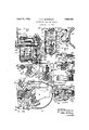
In the accompanying drawings; Figure 1 isa diagrammatic view, mostly in section, of
1930. Serial No. 467,478.
paratus embodying the invention, showing the preferred form' of control mechanism; F ig. 2 is a section taken on the line 22 of Fig. 1; Fig. 3 is anend view of a portion of the control mechanism shownin Fig. 1; Fig. 4 is a plan,part-ly in section of a modified form of control mechanism; Fig. 5 is a side elevation, partly in section of the structure shown in Fig. 4; Fig. 6 is a horizontal section-taken on the line 66 of Fig. 5.
Referring to the drawings, the equipment may comprise an automatic car, air and electric coupler device 6, a bus switch device 7, a magnet valve device 8 for operating the bus switch device 7, and a combined control valve and switch mechanism 9.
If so desired, the couplerdevice 6 may be of the type shown in United States Letters Patent No. 1,571,222 of February 2, 1926, and since the structure shown in the patent is well known in the art, only so much of the car coupler has been illustrated as to clearly understand the present invention.
As shown, each coupler may comprise a hook-shaped projection 10 adapted to engage a corresponding inclined surface of a counterpart coupler and be rigidly clamped therewith by a locking lever 11. V
The car coupler also serves as a coupler for the fluid pressure pipes, such as the main reservoir pipe 12 and the brake pipe 13. In
actual construction the fluidpressure conduits are arranged in vertical alinement, and therefore the brake pipe connection through the coupler is omitted.
vThe conduit through the coupler for the main reservoir line is controlled by a tappet valve 14 which is unseated at the final part of the coupling movement.
A brake pipe closing valve 15 is interposed in the brake pipe 13' and is adapted to be operated by a piston 16, the parts being contained in a casing 17 Fluid under pressure for operating piston 16 maybe supplied through. a'pipe 18, provided with a ball check valve 19, and leading from the combined control valve'and switch mechanism 9,.said'niechanism being operated in a manner to be hereinafter described to to engage the member 24 is a pair of contact fingers 25 and 26. Adjacent to the bus switch device, the bus wire 21 is severed and the two free ends thereof are respectively connected to the contact fingers 25 and 26 in the manrer to be hereinafter more fully described.
A cylinder 27 is formed in the casing of the switch mechanism 7, andmounted in said cylinder is a piston 28 havinga piston stem 29. The outer'end of the stem 29 extends into a spring chamber 30 containing a coil spring 31. Said spring engages a member 32 secured to the stem 29 and tends to move the stem towards the left.
An arm 33 is fixed to the squared end of shaft 23 and said arm is forked to engage over a flattened section of the stem 29. A pin 34 extends out from the flattened portion of the stem and engages in slot 35 in the arm 33.
' The spring finger 26 is secured to a terminal member 36 fixed to a block 37 formedfrom suitable insulating material, the end of the branched sect-ion of the bus wire 21 being also secured to the terminal member 36.
The spring finger 25 is secured to a terminal member 38 which is also fixed to the block 37, the end of the main bus wire 21 being also secured to the terminal member 38.
The magnet valve device 8 may comprise a magnet 39 and a double beat valve 40 adapted to be operated by said magnet. The double beat valve 40 is mounted in a chamber 41'connected tothe piston chamber 42 of the bus switch device 7 by a pipe 43. On one side the valve 40- has a fluted stem 44 extending through a suitable bore 45 in the casing, which connects the chamber 41 to the atmosphere in one position of the valve. On the opposite side of the valve-40 has a fluted stem 46 extending through av suitable bore 47. which connects the chamber 41 with a chamber 48, connected to the main reservoir conduit of the couplerby a pipe 49.
In the present instance, two forms of combined control valve and switch mechanism devices are shown, one form being shown in Figs. 1, 2 and 3, and the other form being shown in Figs. 4, 5 and 6.
As shown in Figs. 1, 2 and 3, the combined control valve and switch mechanism 9'may comprise a casing in which is mounted-a suitable shaft 50. Mounted on the shaft 50, and
spaced a suitable distance apart, is a segmental drum contact member 51 and a cam 52. The outer end of the shaft is provided with an operating lever or handle 53 which is provided with a pin 54 adapted to engage. an abutment 55 in one position of the handle to limit the movement of the handle in a counter-clockwise direction, and adapted to engage an abutment 56 (see Fig. 3) in another position of the handle to limit the movement of the handle in a clockwise direction. When the pin 54 engages the abutment 55, the handle 53 is in the coupled position of the device and when the pin 55 engages the abutment 56 the handle is in uncoupled position of the device.
Adapted to engage the drum contact member 51 are two contact fingers 57 and 58 which are mounted on a block 59 of suitable insulating material, fixed in the casing. The contact finger 57 is connected by a wire 60 to the bus wire 21, the wire 60 being provided with a suitable resistance 61. The contact finger 58 is connected by a wire 62 to one terminal of the magnet 39, the other terminal of said magnet being connected to ground, as at 63.
Mounted in the casing of the combined control valve and switch mechanism 9 and disposed in vertical alinement with the cam 52, are valves 64 and 65.
The valve 64 has a fluted stem extending through a suitable bore 66 formed in the easing between chambers 67 and 68. Chamber 67 is connected to the main reservoir pipe 12 by a pipe 69, and chamber 68 is connected to the pipe 18 heretofore referred to by a passage 70.
The valve has a fluted stem extending through a suitable bore 71 formed in the easing and engaging in chamber 68, the extremity of the stem of valve 64, the construction being such that when the valve 64 is seated, the valve 65 is held off its seat, and when the valve 65 is seated, the valve 64 is held off its seat.
Mounted in the casing between the cam 52 and the valve 65 is a member 72. One end of the member 72 is pivoted on'a pin 73 carried by the casing, the other or outer end of said member being free. Interposed between the member 72 and the valve 65 is a coil spring 74, which is normally extended, and which is adapted to be compressed by said member andthereby act to seat the valve 65.
The side of the member 72 opposite to the spring 74 is provided with an upstanding enlargement, or boss 75 adapted to be engaged by a projecting cam face 76 provided on the cam 52.
For the purpose of limiting the upward swinging movement of the free end of the member 72, the wall of the casing is provided with a laterally extending projection 77.
The cam 52 is provided with a pair of spaced projections 78 and 79, which provide and also through a port 82 to the atmosphere,
and a pair of spring-pressed plungers 83 and 84 adapted to be engaged by a contact'memher 85 carried by the operating handle 86 of the cook 81. The wire 60 is connected to the lunger 83 and the wire 62 is connected to the plunger 84.
When the cars are coupled together and the handle 53 is in coupled position as shown in Figs. 1 and 3, the magnet 39 will be deenergized, since the contact fingers 57 and 58 will be disengaged from the drum contact member 51, so that the circuit from the bus wire 21 to the magnet is open. With the magnet 39 thus deenergized, the lower part of the double beat valve 40 will be held off its seat by spring 87 and the upper part of said valve will be seated, thereby closing the atmospheric exhaust port through the bore 45.
Fluid under pressure is supplied to piston chamber 42 of the bus switch device 7 from the main reservoir 20, through pipe and passage 12, past unseated tappet valve 14 in the coupler, through pipe 49, to chamber 48, and from thence through bore 47, chamber 41, and pipe .43. The piston 28 is thus maintained in the right hand end of chamber 42, and in this position the drum contact member 24 engages the fingers 25 and 26, thereby closing the bus line circuit on the car.
Since the supply of fluid under pressure for operating the bus switch device 7 is controlled by the magnet valve device 8, and .since fluid under pressure is supplied to said bus switch device so as to maintain the same closed when the magnet of said magnet valve device is deenergized, it will be readily understood that the bus switch device will not be operated to open the bus line circuit each time the car passes over a gap in the third rail or trolley. Therefore in a train composed of cars provided with the bus switch control mechanism of the present invention, current will always be supplied to the bus line circuit from the third rail or trolley, since the bus switches will remain closed as long as the cars are coupled up.
When it is desired to uncouple the car, the
handle 53 is turned from the coupled position to the uncoupled position (see Fig. In the initial movement of the handle 53 the drum contact member 51 engages the fingers 57 and 58, thereby closing the circuit through which current is supplied from the bus wire 21 to the magnet 39 of the magnet valve device 8, so that said magnet is energized.
With the energization of magnet 39, the double beat valve 40 will be shifted from its upper position as shown in the drawings to its lower position in which the supply of fluid under pressure is cut off to the piston chamber 42, and in which said piston chamber is connected to the atmosphere, throughq pipe 43, chamber 41, and passage 45.
When the pressure is thus reduced in chamber 42, spring 31 acting on the member 32 shifts the arm 33 toward the left. This action .rotates the drum contact member 24 to its cut-out position in which the main bus line circuit is opened.
In this manner the bus switch device 7 is operated immediately after the operator turns the handle 53 to uncoupled position.
Followin the initial movement of the handle 53 from coupled to uncoupled position, the cam face 76 of the cam 52 engages the boss 75 on the valve actuating member 72 and moves said member downwardly, compressing the spring 74. Since the spring 7 4 acts on the valve 65, said valve will be moved downwardly by the pressure of the spring 74 and since the stem of valve abuts the stem of valve 64, the valve 64 will also be moved downwardly against the pressure of 1ts spring 88. In this way valve 65 is seated and valve 64 unseated.
When the valve 64 is unseated fluid under pressure is supplied to pipe 18 from the main reservoir pipe 12. The brake pipe closing valve 15 is then operated by piston 16 to 4, 5 and 6, is adapted to operate in the manner above described, the initial movement of the handle 86 closing the circuit through the plungers 83 and 84 whereby the magnet 39 will be energized, and the further movement of said handle operating the cook 81 to connect pipes 18 and 69 whereby fluid will be supplied for operating the brake pipe closing valve 15 and the other parts of the coupler in the well known manner.
' While two illustrative embodiments of the invention have been described in detail, it is not my intention to limit their scope to these embodiments or otherwise than by the terms of the appended claims.
Having now described my invention, what I claim as new and desire to secure by Letters Patent, is:
1. The combination with a brake pipe having a fluid pressure operated control valve andian electric switch mechanism for con trollin a train line circuit and a piston operatedly fluid under pressure for actuating said mechanism, of a magnet valve device having a normally de-energized magnet-for controlling a communication through which fluid is supplied to said piston, a switch for controlling the circuit of said magnet, valve means for controlling the supply of fluid for operating said brake pipe control valve, and a single manually operated element for actuating said valve'means and said switch.
2; The combination with a brake pipe having a fluid pressure operated control valve and acoupler havinga fluid pressure conduit and an electric circuit contact'member, of an electric switch mechanism for said electric circuit, said switch mechanism having a piston operated by fluid under pressure for operatingsaid mechanism to close said circuit, a magnet valve device having valve means for controlling a communication through which fluid is supplied from said coupler conduit to said piston, a switch for controlling the circuit of said magnet valve device, valve means for controlling the fluid pressure for operating said brake pipe control valve, and a'singlemanually operated element for actuating said switch and said valve means. In testimony whereof I have hereunto set my hand,.this' 9th day of July, 1930.
HARRY F. WVOERNLEY.
Priority Applications (1)
| Application Number | Priority Date | Filing Date | Title |
|---|---|---|---|
| US467478A US1854725A (en) | 1930-07-12 | 1930-07-12 | Uncoupling valve and switch |
Applications Claiming Priority (1)
| Application Number | Priority Date | Filing Date | Title |
|---|---|---|---|
| US467478A US1854725A (en) | 1930-07-12 | 1930-07-12 | Uncoupling valve and switch |
Publications (1)
| Publication Number | Publication Date |
|---|---|
| US1854725A true US1854725A (en) | 1932-04-19 |
Family
ID=23855865
Family Applications (1)
| Application Number | Title | Priority Date | Filing Date |
|---|---|---|---|
| US467478A Expired - Lifetime US1854725A (en) | 1930-07-12 | 1930-07-12 | Uncoupling valve and switch |
Country Status (1)
| Country | Link |
|---|---|
| US (1) | US1854725A (en) |
-
1930
- 1930-07-12 US US467478A patent/US1854725A/en not_active Expired - Lifetime
Similar Documents
| Publication | Publication Date | Title |
|---|---|---|
| US1854725A (en) | Uncoupling valve and switch | |
| US1349405A (en) | Electric train-wire coupling | |
| US3385454A (en) | Automatic air and electric railway car coupler | |
| US1593711A (en) | Electric coupling device | |
| US1726508A (en) | Control system for train circuits | |
| GB448876A (en) | Automatic coupling for vehicles | |
| US1842639A (en) | Train pipe coupling device | |
| PL170530B1 (en) | Device for changing over from one braking circuit to another in a double-circuit braking stem especially that used on rail vehicles | |
| US1932091A (en) | Controlling valve for couplers | |
| US1952347A (en) | Automatic train wire connecter | |
| US1343857A (en) | Automatic train-stop | |
| US1641071A (en) | Electric train-line switch | |
| US1601151A (en) | Electric coupler interlock | |
| US1403657A (en) | Combined car and air coupling | |
| US1402120A (en) | Car, air, and electric coupling | |
| US1636139A (en) | Car, air, and electric coupling system | |
| US1282777A (en) | Combined car, train-pipe, and electric coupling. | |
| US860948A (en) | Safety device. | |
| US2247677A (en) | Tight-lock car, air, and electric coupler | |
| US1223223A (en) | Automatic car, air, and electric coupling mechanism. | |
| US1927964A (en) | Coupler operating valve | |
| US1608732A (en) | Electric train-line coupler | |
| US1381852A (en) | Automatic car and electric coupling and reversing-switch | |
| US1290066A (en) | Electric train-line coupling. | |
| US1557020A (en) | Door-controlling circuits |