US1854717A - Fastening snap lock for pocketbooks - Google Patents
Fastening snap lock for pocketbooks Download PDFInfo
- Publication number
- US1854717A US1854717A US484526A US48452630A US1854717A US 1854717 A US1854717 A US 1854717A US 484526 A US484526 A US 484526A US 48452630 A US48452630 A US 48452630A US 1854717 A US1854717 A US 1854717A
- Authority
- US
- United States
- Prior art keywords
- casing
- plate
- purse
- latch
- Prior art date
- Legal status (The legal status is an assumption and is not a legal conclusion. Google has not performed a legal analysis and makes no representation as to the accuracy of the status listed.)
- Expired - Lifetime
Links
Images

Classifications
-
- A—HUMAN NECESSITIES
- A44—HABERDASHERY; JEWELLERY
- A44C—PERSONAL ADORNMENTS, e.g. JEWELLERY; COINS
- A44C19/00—Devices for preventing pilfering of watches or jewellery
-
- Y—GENERAL TAGGING OF NEW TECHNOLOGICAL DEVELOPMENTS; GENERAL TAGGING OF CROSS-SECTIONAL TECHNOLOGIES SPANNING OVER SEVERAL SECTIONS OF THE IPC; TECHNICAL SUBJECTS COVERED BY FORMER USPC CROSS-REFERENCE ART COLLECTIONS [XRACs] AND DIGESTS
- Y10—TECHNICAL SUBJECTS COVERED BY FORMER USPC
- Y10S—TECHNICAL SUBJECTS COVERED BY FORMER USPC CROSS-REFERENCE ART COLLECTIONS [XRACs] AND DIGESTS
- Y10S292/00—Closure fasteners
- Y10S292/50—Handbag or purse clasps
Definitions
- This invention relates to an improved purse retainer, and has for one of its principal objects the provision ofmeans for positively retaining a purse or similar object in the owners pocket, thereby eliminating loss due to carelessness or pickpockets.
- One of the important objects of this invention is the provision of means for positively and securely retaining a purse or the like in the desired position in the owners pocket or on the owners person while at the same time permitting of the ready withdrawal thereof when necessary or desirable with aminimum of efiort andtime expenditure.
- Still another and further important object .of this invention is to provide a means for looking or otherwise retaining purses or similar objects in position, which means shall be compact in construction, simple of operation and not at all likely to get out oforder, while at the same time affording a maximum protection.
- the invention in a preferred form, is
- Figure 1 is a side view of the purse orsimilar object, showing the improved purse retainer means of this invention applied thereto, and in position in the users pocket.
- Figure 2 is a front View of the purse retainer element in position in a pocket.
- Figure 3 is a detail view, showing the inner construction of the purse retainer.
- FIG. 4 is a side elevation, partly'in section, of thepurse retainer locking means in open position.
- Figure 5 shows the purse with a portion of a the retainer element of this'invention applied thereto.
- Figure 6 is a bottom plan View of the purse retainer shown in Figure 5.
- Figure 7 is a perspective view of the element which is attached to the purse.
- Figure 8 isianenlargeddetail View .of'the purse retainer locking element showing the interior construction.
- Figure 9 is a sectional view of the device shown in Figure 8, illustrating the same in purse latching position.
- the reference numeral 11 indicates generally a purse or similar object which is adapted to be carried in a'pocket 12 or the like, and which-purses, usually containing valuable matter,.are subject to thievery and il-lSO should be protected against accidental oss.
- the present invention resides in the application of a locking means to the pocket to which locking means the purse can be attached and asreadily withdrawn by the user, while at-the same time accidental loss or removal of the same'by a pickpocket is positively prevented.
- the locking means of this invention comprises essentially a casing 10 to which the purse is adapted to be removably attached by means of a latch adapted to interfit with the plate 16 which is mounted 011 one end or 70 edge of the purse by means of screws, rivets, or the like 18, as best shown in Figure 5.
- This plate 16 has a slot 20 therein adapted for the reception of a latching tongue 22, and the plate is also provided with outwardly extending integral lugs 24, which contact with the lower edges of the other portions of the purse, thereby preventing undesirable buckling when use ismade of the locking means.
- the latching tongue 22 is slidably and pivotally mounted in the casing 10, this tongue forming the upper end of a channel-shaped member 30, which is pivotally and slidably mounted in a pair'of outstanding lugs 32 attachedto one side of the casing 10.
- Apin 9 34 passes through 'the'lugs 32 and also through the channel walls 30, an elongated opening 36 being provided in the channel walls 30 for slidable reception of the pin 34, whereby this channel element can be moved vertically with respect to the lugs 32 andis also pivotally mounted with respect therewith.
- the bottom of the channel member 32 is cut away as shown at 38, and through this opening projects a latching lug or the like 40 which is aifirged to one side of the casing 10 and which is provided with a shoulder 42 with which is adapted to contact that portion of the channel member 30 adjacent the opening 88 for a locking relationship as best shown in Figure 4.
- a spring 44 is coiled around the pin 34 and has a free end 46 contacting with apin 48 so that the entire channel member 30 with its latching end 22 will be normally forced outwardly into purse retaining position whenever this member is I pushed upwardly and out of contact with the locking shoulder 42 of the lug 40.
- a spring 50 is provided wherebythe channel member 30 is normally pulled downwardly with respect to the casing 10 and into retracted position as shown in Figure 4.
- a U-shaped element 52 Pivotally mounted in the lower end of the channel member 30 is a U-shaped element 52, this pivotal mounting being accomplished by means of a pin 54, and the connection between the spring 50 and the channel-shaped member 30 is formed by hooking the upper end of the spring 50 into the cross-piece 56 of the U-shaped member 52 as shown in Figure 4.
- ends 64 of the plate 62 are formed with openings therein through which are fitted wedgeshaped locking elements 68 which in turn maintain plate 70 in position whereby the plate 62 is positively maintained in'a proper horizontal position with respect to the casing 10 while at the same time being allowed to freely slide in the slot 66.
- a pair of helical springs 72 are fastened to the top of the plate 62 and to the bottomof the casing 10, whereby this plate is normally maintained in the lower ends of the slot 66.
- straps 76 Fastened by means of rivets 7 4 or the like to the lower edges of the plate 62 are straps 76 which terminate in extensions 7 8 which pass upwardly through openings in the top of the casing 10 and are adapted to be fastenedby means of stitching or the like 80 to the interior opposite sides of a pocket 12.
- the operator exercises a downward pressure thereon forcing the casing 10 downwardly and causing a relative upward motion of the plate 62 which contacts with the forwardly projecting edges of the channel-shaped member 30 as illustrated in Figure 9, forcing the latch member 22 rearwardly into the position shown in Figure 4 whereupon the purse can be withdrawn inasmuch as the channel-shaped member is held in retracted position by the notch 42.
- a purse retainer including in combination, an element adapted to be attached to a purse, and a lockingmeans for removable association with such element, said locking means adapted to be attached to the interior of a pocket, and comprising a spring-impelled latch, said latch being normally maintained in open position for the reception and later securing of a purse.
- a purse retainer including in combination, an element adapted to be attached to a purse, and a locking means for removable association with such element, said locking means adapted to be attached to the interior of a pocket, and comprising a spring-impelled latch, said latch being normally maintained 111 open position for the reception and later securing of a purse, and means for impelling the latch into purse securing position upon application of the purse thereto.
- a locking means for purses adapted to be secured to the interior of a pocket
- said locking means comprising a casing, a retractable latch in the casing, straps for securing the casing to the interior of a pocket, and means connected With the straps for operating the retractable latch, said means comprising a plate slidably mounted in the casing, said plate having an opening therein, and latch releasing means operatively connected with the lower edge of the opening.
- a locking means for purses adapted to be secured to the interior of a pocket
- said locking means comprising a casing, a retractable latch in the casing, straps for securing the casing to the interior of a pocket, and means connected with the straps for operating the retractable latch, said means comprising a plate slidably mounted in the easing, said plate having an opening therein, and latch releasing means operatively connected with the lower edge of the opening, together with latch retracting means operatively associated with the upper edge of the late.
- a locking means for purses adapted to be secured to the interior of a pocket
- said locking means comprising a casing, a retractable latch in the casing, straps for securing the casing to the interior of a pocket, and means connected with the straps for operating the retractable latch
- said means comprising a plate slidably mounted in the casing, said plate having an opening therein, and latch releasing means operatively connected with the lower edge of the opening, said latch releasing means comprising a U-shaped element having its legs normally projecting through said opening, said element adapted to be moved upwardly upon a corresponding relative upward movement of the plate.
- a locking means for purses adapted to be secured to the interior of a pocket
- said locking means comprising a casing, a retractable latch in the casing, straps for securing the casing to the interior of a pocket, and means connected with the straps for operating the retractable latch, said means comprising a plate slidably mounted in the easing, said plate having an opening therein, and latch releasing means operatively c011- nectedwith the lower edge ofthe-o'pening,
- latch-retracting means comprising: a channel-shapedelement pivotally and .slidablymounted in the casing, andada-pted to be movedrearwardly about its pivotal mounting upon a relative upwardamotionof the plate .thereagainst.
- said locking means comprising a casing, a retractable latch in the casing, straps forsecuring the casing to the interior of a :pocket, and means connected with the straps .for operating the retractable latch, said meanszcomprising a plate slidably mounted in the casing, said plate having an opening therein, and latch releasing means operatively connected with the lower edge of the opening, said latch releasing means comprising a U-shaped element having its legs normally projecting through said opening, said element adapted to be moved upwardly upon a corresponding relative upward movement of gether with springs for normally maintaining the plate in its lowermost position and the U-shaped element in position with its legs projecting through the opening in the plate.
- a locking means for purses adapted to be secured to the interior of a pocket
- said locking means comprising a casing, a retractable latch in the casing, straps for securing the casing to the interior of a pocket, and means connected with the erating the retractable latch
- said means comprising a plate slidably mounted in the easing, said plate having an opening therein, and latch releasing means operatively connected with the lower edge of the opening, together with latch retracting means operatively associated with the upper edge of the plate
- said latch-retracting means comprising a channel-shaped element pivotally and slidably mounted in the casing, and adapted to be moved rearwardly about its pivotal mounting upon a relative upward motion of the plate thereagainst, together with a coil spring for normally forcing the channel-shaped member with its attached latch into forward purse locking position.
- a locking means for purses adapted to be secured to the interior of a pocket, said locking means comprising a casing, a re tractable latch in the casing, straps for securing the casing to the interior of a pocket, and means connected with the straps for operating the retractable latch, said means comprising a plate slidably mounted'in the easing, said and latch releasing means operatively connected with the lower edge of the opening, together with latch retracting means operatively associated with the upper edge of the 7.
- said latch-retracting means comprising "i133 a channel-shaped element pivotally and slidably mounted in the casing, and adapted to be moved rearwardly about its pivotal mounting upon a relative upward motion of the plate thereagainst, together with a coil spring for normally forcing the channel-shaped :meniberwith its attached latch into forward purse locking position, and a notched lug fastened to the casing and projecting through an opening in the bottom of the channelshaped member, and adapted for locking contact with the corresponding edge of the open- 7 ing in the channel-shaped member for retaining the latch forming part of said channelshaped member in purse releasing position.
Landscapes
- Purses, Travelling Bags, Baskets, Or Suitcases (AREA)
Description
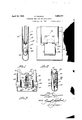
April 19, 1932. R. PEARSON FASTENING SNAP LOOK FOR POCKETBOOKS Sheets-Sheet 1 Filed Sept. 26. 1930 .llll I l fi 5 p4 G/VAP PEA/1750A! Patented Apr. 19, 1932 RAGNAR PEARSON, OF CHICAGO, ILLINOIS I FASTENING SNAP .LooK FOR rocxnrrooxs Application filed September 26,1930. 1 Serial No. 484,526.
This invention relates to an improved purse retainer, and has for one of its principal objects the provision ofmeans for positively retaining a purse or similar object in the owners pocket, thereby eliminating loss due to carelessness or pickpockets.
One of the important objects of this invention is the provision of means for positively and securely retaining a purse or the like in the desired position in the owners pocket or on the owners person while at the same time permitting of the ready withdrawal thereof when necessary or desirable with aminimum of efiort andtime expenditure.
Still another and further important object .of this invention is to provide a means for looking or otherwise retaining purses or similar objects in position, which means shall be compact in construction, simple of operation and not at all likely to get out oforder, while at the same time affording a maximum protection.
Other and further important objects of the invention will be apparent from the disclosures in the accompanying drawings and following specification.
The invention, in a preferred form, is
shown in the drawings and hereinafter more fully described.
In the drawings:
Figure 1 is a side view of the purse orsimilar object, showing the improved purse retainer means of this invention applied thereto, and in position in the users pocket.
Figure 2 is a front View of the purse retainer element in position in a pocket.
Figure 3 is a detail view, showing the inner construction of the purse retainer.
- Figure 4 is a side elevation, partly'in section, of thepurse retainer locking means in open position.
Figure 5 shows the purse with a portion of a the retainer element of this'invention applied thereto.
Figure 6 is a bottom plan View of the purse retainer shown in Figure 5.
. Figure 7 is a perspective view of the element which is attached to the purse. Figure 8 isianenlargeddetail View .of'the purse retainer locking element showing the interior construction.
Figure 9 is a sectional view of the device shown in Figure 8, illustrating the same in purse latching position.
As shownin the drawings:
The reference numeral 11 indicates generally a purse or similar object which is adapted to be carried in a'pocket 12 or the like, and which-purses, usually containing valuable matter,.are subject to thievery and il-lSO should be protected against accidental oss.
The present invention resides in the application of a locking means to the pocket to which locking means the purse can be attached and asreadily withdrawn by the user, while at-the same time accidental loss or removal of the same'by a pickpocket is positively prevented.
The locking means of this invention comprises essentially a casing 10 to which the purse is adapted to be removably attached by means of a latch adapted to interfit with the plate 16 which is mounted 011 one end or 70 edge of the purse by means of screws, rivets, or the like 18, as best shown in Figure 5. This plate 16 has a slot 20 therein adapted for the reception of a latching tongue 22, and the plate is also provided with outwardly extending integral lugs 24, which contact with the lower edges of the other portions of the purse, thereby preventing undesirable buckling when use ismade of the locking means.
The latching tongue 22 is slidably and pivotally mounted in the casing 10, this tongue forming the upper end of a channel-shaped member 30, which is pivotally and slidably mounted in a pair'of outstanding lugs 32 attachedto one side of the casing 10. Apin 9 34 passes through 'the'lugs 32 and also through the channel walls 30, an elongated opening 36 being provided in the channel walls 30 for slidable reception of the pin 34, whereby this channel element can be moved vertically with respect to the lugs 32 andis also pivotally mounted with respect therewith.
' The bottom of the channel member 32 is cut away as shown at 38, and through this opening projects a latching lug or the like 40 which is aifirged to one side of the casing 10 and which is provided with a shoulder 42 with which is adapted to contact that portion of the channel member 30 adjacent the opening 88 for a locking relationship as best shown in Figure 4. A spring 44 is coiled around the pin 34 and has a free end 46 contacting with apin 48 so that the entire channel member 30 with its latching end 22 will be normally forced outwardly into purse retaining position whenever this member is I pushed upwardly and out of contact with the locking shoulder 42 of the lug 40. A spring 50 is provided wherebythe channel member 30 is normally pulled downwardly with respect to the casing 10 and into retracted position as shown in Figure 4.
Pivotally mounted in the lower end of the channel member 30 is a U-shaped element 52, this pivotal mounting being accomplished by means of a pin 54, and the connection between the spring 50 and the channel-shaped member 30 is formed by hooking the upper end of the spring 50 into the cross-piece 56 of the U-shaped member 52 as shown in Figure 4.
This connection is behind the pivotal point 54 and tends to force the lower ends of the U-shaped member 52 outwardly into the position illustrated in Figure 4. In this position, the lower edges of the two legs of the U- shaped member 52 contact with the lower edge 60 of an opening formed in a plate 62 which plate is slidably tted in the' casing 10 by having its edges 64 protrude through slots 66 formed in the ends of the casing 10. The
Fastened by means of rivets 7 4 or the like to the lower edges of the plate 62 are straps 76 which terminate in extensions 7 8 which pass upwardly through openings in the top of the casing 10 and are adapted to be fastenedby means of stitching or the like 80 to the interior opposite sides of a pocket 12.
When it is desired to lock the purse in position in the users pocket, it is merely placed in the pocket with the plate 16 lowermost, and the plate 16 will slide down between the straps 7 8 and then into the slot formed in the top of the casing 10, the plate being guided by the inturned sloping edges 82 of the upper portion of the casing 10 as best shown in Figure 9. Upon contacting with the bottom of the slot 84, downward pressure by the operator will cause the sides of the casing 10 to move downwardly with respect to the plate 62 which plate is maintained in relative position by means of the attached straps 7 67 8.
Downward motion of the casing 10 with its interior appurtenances will cause pressure to be exerted between the lower ends of the legs 52 and the edge 60 of the opening in the plate 62 whereupon the U-shaped member 52 will be forced upwardly against the tension of the spring 50, as this member is mounted by means of the pin 54 in the channel-shaped element 30. This channel-shaped element will also be constrained to move relatively upwardly in the casing 10 lifting it out of locking position with respect to the notch 42, and allowing the coil spring 44 to force the latching element 22 forwardly into locking position with respect to the opening 20 in the plate 16. In this way, the purse is securely locked in position against accidental loss and even against unauthorized withdrawal thereof by a thief or pickpocket.
In order to release the purse, the operator exercises a downward pressure thereon forcing the casing 10 downwardly and causing a relative upward motion of the plate 62 which contacts with the forwardly projecting edges of the channel-shaped member 30 as illustrated in Figure 9, forcing the latch member 22 rearwardly into the position shown in Figure 4 whereupon the purse can be withdrawn inasmuch as the channel-shaped member is held in retracted position by the notch 42.
It will be evident that herein is provided a simple yet convenient and positively operating means for securely locking purses or similar articles in an owners pocket or the like, and which while positively preventing accidental loss or deliberate thievery thereof, will at the same time render quite easy the withdrawal of the purse or other object by the legitimate owner or user. Further, the device is very compact, can be readily installed, and is not at all likely to become damaged or to get out of order in use.
I am aware that many changes may be made and numerous details of construction varied throughout a wide range without departing from the principles of this invention, and I, therefore, do not purpose limiting the patent granted hereon otherwise than as necessitated by the prior art.
I claim as my invention:
1. A purse retainer, including in combination, an element adapted to be attached to a purse, and a lockingmeans for removable association with such element, said locking means adapted to be attached to the interior of a pocket, and comprising a spring-impelled latch, said latch being normally maintained in open position for the reception and later securing of a purse.
2. A purse retainer, including in combination, an element adapted to be attached to a purse, and a locking means for removable association with such element, said locking means adapted to be attached to the interior of a pocket, and comprising a spring-impelled latch, said latch being normally maintained 111 open position for the reception and later securing of a purse, and means for impelling the latch into purse securing position upon application of the purse thereto.
3. A locking means for purses, adapted to be secured to the interior of a pocket, said locking means comprising a casing, a retractable latch in the casing, straps for securing the casing to the interior of a pocket, and means connected With the straps for operating the retractable latch, said means comprising a plate slidably mounted in the casing, said plate having an opening therein, and latch releasing means operatively connected with the lower edge of the opening. 7
4. A locking means for purses, adapted to be secured to the interior of a pocket, said locking means comprising a casing, a retractable latch in the casing, straps for securing the casing to the interior of a pocket, and means connected with the straps for operating the retractable latch, said means comprising a plate slidably mounted in the easing, said plate having an opening therein, and latch releasing means operatively connected with the lower edge of the opening, together with latch retracting means operatively associated with the upper edge of the late. p 5. A locking means for purses, adapted to be secured to the interior of a pocket, said locking means comprising a casing, a retractable latch in the casing, straps for securing the casing to the interior of a pocket, and means connected with the straps for operating the retractable latch, said means comprising a plate slidably mounted in the casing, said plate having an opening therein, and latch releasing means operatively connected with the lower edge of the opening, said latch releasing means comprising a U-shaped element having its legs normally projecting through said opening, said element adapted to be moved upwardly upon a corresponding relative upward movement of the plate.
6. A locking means for purses, adapted to be secured to the interior of a pocket, said locking means comprising a casing, a retractable latch in the casing, straps for securing the casing to the interior of a pocket, and means connected with the straps for operating the retractable latch, said means comprising a plate slidably mounted in the easing, said plate having an opening therein, and latch releasing means operatively c011- nectedwith the lower edge ofthe-o'pening,
. together with latch retracting means operatively associated'with the upper edge 'ofsthe plate, said latch-retracting means comprising: a channel-shapedelement pivotally and .slidablymounted in the casing, andada-pted to be movedrearwardly about its pivotal mounting upon a relative upwardamotionof the plate .thereagainst.
be secured to the interior of a pocket,vsaid locking means comprisinga casing, a retractable latch in the casing, straps forsecuring the casing to the interior of a :pocket, and means connected with the straps .for operating the retractable latch, said meanszcomprising a plate slidably mounted in the casing, said plate having an opening therein, and latch releasing means operatively connected with the lower edge of the opening, said latch releasing means comprising a U-shaped element having its legs normally projecting through said opening, said element adapted to be moved upwardly upon a corresponding relative upward movement of gether with springs for normally maintaining the plate in its lowermost position and the U-shaped element in position with its legs projecting through the opening in the plate.
8. A locking means for purses, adapted to be secured to the interior of a pocket, said locking means comprising a casing, a retractable latch in the casing, straps for securing the casing to the interior of a pocket, and means connected with the erating the retractable latch, said means comprising a plate slidably mounted in the easing, said plate having an opening therein, and latch releasing means operatively connected with the lower edge of the opening, together with latch retracting means operatively associated with the upper edge of the plate, said latch-retracting means comprising a channel-shaped element pivotally and slidably mounted in the casing, and adapted to be moved rearwardly about its pivotal mounting upon a relative upward motion of the plate thereagainst, together with a coil spring for normally forcing the channel-shaped member with its attached latch into forward purse locking position.
9. A locking means for purses, adapted to be secured to the interior of a pocket, said locking means comprising a casing, a re tractable latch in the casing, straps for securing the casing to the interior of a pocket, and means connected with the straps for operating the retractable latch, said means comprising a plate slidably mounted'in the easing, said and latch releasing means operatively connected with the lower edge of the opening, together with latch retracting means operatively associated with the upper edge of the 7. A locking means for purses, adapted-to straps for op-" plate having an opening therein;
plate, said latch-retracting means comprising "i133 a channel-shaped element pivotally and slidably mounted in the casing, and adapted to be moved rearwardly about its pivotal mounting upon a relative upward motion of the plate thereagainst, together with a coil spring for normally forcing the channel-shaped :meniberwith its attached latch into forward purse locking position, and a notched lug fastened to the casing and projecting through an opening in the bottom of the channelshaped member, and adapted for locking contact with the corresponding edge of the open- 7 ing in the channel-shaped member for retaining the latch forming part of said channelshaped member in purse releasing position. In testimony whereof I aflix my signature.
RAGNAR PEARSON.
Priority Applications (1)
| Application Number | Priority Date | Filing Date | Title |
|---|---|---|---|
| US484526A US1854717A (en) | 1930-09-26 | 1930-09-26 | Fastening snap lock for pocketbooks |
Applications Claiming Priority (1)
| Application Number | Priority Date | Filing Date | Title |
|---|---|---|---|
| US484526A US1854717A (en) | 1930-09-26 | 1930-09-26 | Fastening snap lock for pocketbooks |
Publications (1)
| Publication Number | Publication Date |
|---|---|
| US1854717A true US1854717A (en) | 1932-04-19 |
Family
ID=23924515
Family Applications (1)
| Application Number | Title | Priority Date | Filing Date |
|---|---|---|---|
| US484526A Expired - Lifetime US1854717A (en) | 1930-09-26 | 1930-09-26 | Fastening snap lock for pocketbooks |
Country Status (1)
| Country | Link |
|---|---|
| US (1) | US1854717A (en) |
-
1930
- 1930-09-26 US US484526A patent/US1854717A/en not_active Expired - Lifetime
Similar Documents
| Publication | Publication Date | Title |
|---|---|---|
| JP7083187B2 (en) | Mounting system with articulation | |
| US4881672A (en) | Safety attachment pruse hook | |
| US4103949A (en) | Safety door latch | |
| US20090139283A1 (en) | Hidden lock locked to an inner side of a doorplate | |
| US3904091A (en) | Sidearm holsters | |
| US1599920A (en) | Latch-key-holding device for belt buckles and similar articles | |
| US1756775A (en) | Extensible fastening | |
| US2962138A (en) | Collapsible flat-lying luggage handle | |
| US1854717A (en) | Fastening snap lock for pocketbooks | |
| US2672043A (en) | Key retaining device | |
| US1235075A (en) | Box-fastener. | |
| US3266110A (en) | Seat belt buckle | |
| US3478547A (en) | Luggage locks | |
| US2382756A (en) | Hasp lock | |
| US3390556A (en) | Luggage locks | |
| CN220124125U (en) | Luggage case with pulley locking function | |
| US3558167A (en) | Combined latch and lock mechanism | |
| US2065946A (en) | Buckle | |
| US2574023A (en) | Wallet protector | |
| US2065036A (en) | Key protector | |
| US3373749A (en) | Binders or holders for books | |
| US1567461A (en) | Locked pocketbook appliance | |
| US1652676A (en) | Trunk lock and drawbolt | |
| US6983518B2 (en) | Buckle for belts | |
| US1372697A (en) | Watch-protector |