US1854716A - Sound instrument - Google Patents
Sound instrument Download PDFInfo
- Publication number
- US1854716A US1854716A US334659A US33465929A US1854716A US 1854716 A US1854716 A US 1854716A US 334659 A US334659 A US 334659A US 33465929 A US33465929 A US 33465929A US 1854716 A US1854716 A US 1854716A
- Authority
- US
- United States
- Prior art keywords
- diaphragm
- gaskets
- sound
- gasket
- instrument
- Prior art date
- Legal status (The legal status is an assumption and is not a legal conclusion. Google has not performed a legal analysis and makes no representation as to the accuracy of the status listed.)
- Expired - Lifetime
Links
Images
Classifications
-
- H—ELECTRICITY
- H04—ELECTRIC COMMUNICATION TECHNIQUE
- H04R—LOUDSPEAKERS, MICROPHONES, GRAMOPHONE PICK-UPS OR LIKE ACOUSTIC ELECTROMECHANICAL TRANSDUCERS; ELECTRIC HEARING AIDS; PUBLIC ADDRESS SYSTEMS
- H04R7/00—Diaphragms for electromechanical transducers; Cones
- H04R7/16—Mounting or tensioning of diaphragms or cones
- H04R7/18—Mounting or tensioning of diaphragms or cones at the periphery
- H04R7/22—Clamping rim of diaphragm or cone against seating
Definitions
- This invention relates to sound producing instruments and particularly, to the means for supporting the electrically, acoustically, mechanically or magnetically operated dia- 5 phragm thereof, and to the means for venting the interior of the instrument for preventing undesirable concussions upon the ear of the listener, and reducing the retarded activity.
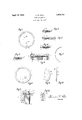
- Fig. 1 is a bottom plan view of a diaphragm to the peripheral portion of which my improved cushioning and supporting means has been applied.
- Fig. 2 is a vertical section of a part of the same, showing one form of my improved cushioning means.
- Figs. 3, 4 and 5 are similar views of the same, showing other forms or arrangements thereof.
- Fig. 6 is a vertical section of part of a receiver showing my invention applied thereto.
- Fig. 7 is a top plan view of a portionof the ring or washer which I prefer to use with my improved diaphragm.
- Fig. 8 is a similar top plan view of a diaphragm provided with venting or breather '0 passages.
- Fig. 9 is a similar view of part of the diaphragm showing another form of the vent or breather passage.
- Fig. 10 is an edge view of the same.
- Fig. 11 is a vertical section, enlarged, of part of a sound instrument showing the screw threads holding the parts of the instrument together, and showing in exaggerated fashion the breather passage communicating with the tone chamber, and
- Fig. 12 is a similar view of another form of the threads.
- the present invention is in part, in the natureof an improvement upon the diaphragm mounting means shown and described in my co-pending application for patent for diaphragm and mounting therefor, Ser1al No. 320,229, filed November 19th, 1928, wherein I have shown a diaphragm, in which the peripheral edge and peripheral surfaces are encased in paper gaskets secured in place preferably by a gum rubber cement.
- the ring 15 may be interposed between the edge portion 16 of the diaphragm and a suitable lower gasket 17.
- a narrow ring 15 may be arranged directly on both faces of the diaphragm and maintained in place by the outer gaskets 17 and 18, being preferably secured in place to one of the outer gaskets by a yieldable cement such as a gum rubber cement.
- the rings 15 may be cemented or otherwise secured to the outside of the gaskets 17 or 18 so as to come into direct contact with the seats 11 and 12 respectively, and as shown in Fig. 5, additional spacing and cushioning gaskets as 9 may be used adjacent the seat.
- the diaphragm By reducing the area of support of the diaphragm and spacing the supported edge of the diaphragm slightly away from the seats therefor by a more or less compressible or yieldable ring or gasket, the diaphragm is left substantially free to retain its original shape and spacing from the magnets 19 without distortion under pressure and thereby cannot fail to perform its proper function in an eflicient manner.
- the various rings and gaskets 15, 17 and 18 of comparatively thin paper said gaskets may be made of other suitable materials having the same properties and functioning in the same manner such as for instance, fibre, celluloid and the like, provided only that the ring is sufficiently thin and narrow to function as described.
- the ring 15 may be secured to the diaphragm or to a gasket which is secured to the diaphragm with the ring therebetween, or to one or more loose, unsecured gaskets, which may be arranged between the diaphragm and either or both of the instrument seats.
- breather means in the form of vents, passages or holes through the cap 14 and extending between the tone chamber 20 and the exterior of the instrument.
- the threads by means of which the parts 13 and 14 are secured together, for this purpose.
- the upper gasket 18 may be grooved at one or more places as by means of suitable narrow grooves 21 so that air may pass from the chamber 20 through the grooves and out to the exterior of the instrument, as through the passages 22 between the threads 23 and 2 1, it being well known that threads of this type are sufficiently loose when not clogged with accumulations of dust or dirt or other foreign matter to provide a helical or spiral passage therethrough suitable for the purpose described.
- the threads may be of the type known as United States standard threads in which the points or sharp edges of the V threads have been somewhat flattened to provide a larger space 22, as illustrated in Fig. 11.
- longitudinal grooves such as 25 coaxial with the casing, may be made across the threads to provide a passage through which the air may pass under the concussion from the chamber 20 through the grooves 21 and through the slot 25 to the outside.
- the groove leading from the chamber 20, instead of being cut into and through the gasket, may be formed by using two or more gaskets as 26 and 27 and slotting the under gasket 27 nearest the diaphragm 10, as by means of suitable slots 28 leading from the chamber 20 to the annular chamber 30 on the other side of the diaphragm.
- the var1- ous gaskets shown herein may be secured to the diaphragm edges, or may be made in the form of separate gaskets as may be found desirable.
- compressible flat gaskets of the type shown in my prior applica ion above referred to may be secured to thediaphragm and spacing gaskets may be used between the diaphragm gaskets and the seat, to which spacing gaskets may be secured the narrow ring 15.
- a threaded casing a cap engaging said casing, diaphragm seats on said casing and cap, a diaphragm arranged between said seats, and a flat ring narrower than either seat and of less thickness than that of the diaphragm interposed between the diaphragm and at least one of the seats for minimizing the area of pressure put by the adjacent seat on the diaphragm, said ring being arranged inwardly of the peripheral edge of the diaphragm.
- a threaded casing screwed on to said casing and having a tone chamber therein, a diaphragm seat on said casing and cap, a diaphragm clamped by said casing and cap between said seats, and cushioning means between the diaphragm and at least one of the seats, said means having a breather passage therethrough connecting said tone chamber with the threads of the casing and cap.
- a diaphragm a diaphragm, edge gaskets on said diaphragm, cooperating threaded means for removably clamping a diaphragm therebetween, and a narrow thin flat ring arranged to minimize the area of pressure put by the clamping means on the diaphragm, the edge gaskets having a breather passage therethrough connecting the interior with the threads of the clamping means.
- a diaphragm having a breather passage therethrough communieating with the interior of one of the clamping elements and with the threads thereof.
- a diaphragm, and edge gaskets therefor therefor, one of said gaskets having a narrow breather passage therein.
- an instrument of the class described comprising a casing, a cap member, a diaphragm member, a central sound chamber, seating surfaces provided by said members, for said casing, cap and diaphragm of which. at least one is a breather vent provided for cooperatively uniting the central sound chamber with the outer air.
- a sound instrument comprising a casing, a cap and a diaphragm, a vent in one of said parts, a central sound chamber, an escapement chamber, said vent uniting said central sound chamber with said escapement chamber.
- a sound instrument of the class described comprising clamping members having each a diaphragm seat, a diaphragm for the same, an edge gasket, a narrower gasket arranged concentrically with said first mentioned gasket and secured thereby to the diaphragm.
- a sound instrument of the class described comprising clamping members having each a diaphragm seat, a diaphragm, a central sound chamber, a gasket, a second gasket of narrower construction arranged concentrically with said first mentioned gasket, and a breather vent uniting the central sound chamber with the outer air.
Landscapes
- Engineering & Computer Science (AREA)
- Multimedia (AREA)
- Physics & Mathematics (AREA)
- Acoustics & Sound (AREA)
- Signal Processing (AREA)
- Diaphragms For Electromechanical Transducers (AREA)
Description
' Patented Apr. 19, 1932 PATENT OFFICE HERMAN G. IPAPE, OF NEW YORK, N. Y.
SOUND INSTRUMENT Application filed January 24, 1929. Serial No. 334,659.
This invention relates to sound producing instruments and particularly, to the means for supporting the electrically, acoustically, mechanically or magnetically operated dia- 5 phragm thereof, and to the means for venting the interior of the instrument for preventing undesirable concussions upon the ear of the listener, and reducing the retarded activity.
The various objects of my invention will be clear from the description which follows and from the drawings, in which,
Fig. 1 is a bottom plan view of a diaphragm to the peripheral portion of which my improved cushioning and supporting means has been applied.
Fig. 2 is a vertical section of a part of the same, showing one form of my improved cushioning means.
Figs. 3, 4 and 5 are similar views of the same, showing other forms or arrangements thereof.
Fig. 6 is a vertical section of part of a receiver showing my invention applied thereto.
Fig. 7 is a top plan view of a portionof the ring or washer which I prefer to use with my improved diaphragm.
Fig. 8 is a similar top plan view of a diaphragm provided with venting or breather '0 passages.
Fig. 9 is a similar view of part of the diaphragm showing another form of the vent or breather passage.
Fig. 10 is an edge view of the same.
Fig. 11 is a vertical section, enlarged, of part of a sound instrument showing the screw threads holding the parts of the instrument together, and showing in exaggerated fashion the breather passage communicating with the tone chamber, and
Fig. 12 is a similar view of another form of the threads.
The present invention is in part, in the natureof an improvement upon the diaphragm mounting means shown and described in my co-pending application for patent for diaphragm and mounting therefor, Ser1al No. 320,229, filed November 19th, 1928, wherein I have shown a diaphragm, in which the peripheral edge and peripheral surfaces are encased in paper gaskets secured in place preferably by a gum rubber cement.
In that practical embodiment of my invention which I have illustrated herein by way of example, I prefer to interpose between the diaphragm 10 and the seats 11 and 12 therefor, made respectively, in the casing member 13 and the cap 14 of any sound producing instrument of the conventional types, one or more fiat paper rings or gaskets as 15 made as narrow as possible, and narrower than either of the seats 11 or 12. By the use of at least one such very narrow gasket, the pressure put upon the diaphragm through the seats 11 and 12, when the parts 13 and 14. are screwed together, is confined to a comparatively narrow area substantially a circular line on the periphery of the diaphragm, with the resulting advantage of elimination of harshness in the reproduced sound, elimination of tone distortion and of possible distortion of the diaphragm, and other advantages as Will hereinafter appear.
As shown in Fig. 2, the ring 15 may be interposed between the edge portion 16 of the diaphragm and a suitable lower gasket 17. As illustrated in Fig. 3, a narrow ring 15 may be arranged directly on both faces of the diaphragm and maintained in place by the outer gaskets 17 and 18, being preferably secured in place to one of the outer gaskets by a yieldable cement such as a gum rubber cement.
here two opposed rings 15, one between the diaphragm 10 and each seat 11 and 12, are used, it will be obvious that even though the rings are not perfectly aligned or exactly above each other, distortion of the diaphragm under pressure put thereon by seats 11 and 12 which may not be perfectly parallel or not perfectly plane surfaces, is avoided.
This is so because the flat rings necessarily become so arranged that they press against each other, maintaining the peripheral portion of the diaphragm in its normal plane, even though the rings may be slightly out of line, in distinction from the operation of edged or curved devices for putting pressure on the diaphragm. It will be understood that if the seat 12 is quite narrow, as is usually the case, no ring 15 need be used thereunder.
As shown in Fig. 4, the rings 15 may be cemented or otherwise secured to the outside of the gaskets 17 or 18 so as to come into direct contact with the seats 11 and 12 respectively, and as shown in Fig. 5, additional spacing and cushioning gaskets as 9 may be used adjacent the seat.
By using such a narrow paper ring 15, not only is the diaphragm more or less hingedly and yieldingly supported upon the seats therefor, but the diaphragm is free to retain its proper normal shape when clamped and thereby stressed. This is an important feature of my invention since it is well known that in the manufacture of sound producing instruments, the seats for the diaphragm in the casing and cap cannot always be so accurately made as to lie in perfect planes. On the contrary, such seats are often slightly throughout or in part convexly or concavely conical so that when the seats are screwed upon the diaphragm, the diaphragm may be come convexly or concavely distorted by being pressed toward and conformed to the imperfectly shaped seat, and thereby fail to properly reproduce the sound.
By reducing the area of support of the diaphragm and spacing the supported edge of the diaphragm slightly away from the seats therefor by a more or less compressible or yieldable ring or gasket, the diaphragm is left substantially free to retain its original shape and spacing from the magnets 19 without distortion under pressure and thereby cannot fail to perform its proper function in an eflicient manner.
It will be understood that while I prefer to make the various rings and gaskets 15, 17 and 18 of comparatively thin paper, said gaskets may be made of other suitable materials having the same properties and functioning in the same manner such as for instance, fibre, celluloid and the like, provided only that the ring is sufficiently thin and narrow to function as described. It will also be understood that the ring 15 may be secured to the diaphragm or to a gasket which is secured to the diaphragm with the ring therebetween, or to one or more loose, unsecured gaskets, which may be arranged between the diaphragm and either or both of the instrument seats.
As is well illustrated in my prior Patent No. 1,560,303 for a double ear-piece, dated November 5th, 1925, it is desirable to provide some means communicating with the interior tone chamber 20 of the instrument and with the outside atmosphere whereby a breather or relief passage is provided for the air in the interior of said chamber. Under sudden pressure due to various causes such as a large volume of sound, the concussion may be suflicient to tend to injure the ear of the listener if no such breather passage is provided, as well as to distort the sound.
In my prior patent, I have shown such breather means in the form of vents, passages or holes through the cap 14 and extending between the tone chamber 20 and the exterior of the instrument. In the present form of my invention, however, I prefer to utilize the threads, by means of which the parts 13 and 14 are secured together, for this purpose. In this case, the upper gasket 18 may be grooved at one or more places as by means of suitable narrow grooves 21 so that air may pass from the chamber 20 through the grooves and out to the exterior of the instrument, as through the passages 22 between the threads 23 and 2 1, it being well known that threads of this type are sufficiently loose when not clogged with accumulations of dust or dirt or other foreign matter to provide a helical or spiral passage therethrough suitable for the purpose described.
If desired, however, the threads may be of the type known as United States standard threads in which the points or sharp edges of the V threads have been somewhat flattened to provide a larger space 22, as illustrated in Fig. 11. If found convenient and desirable in addition, longitudinal grooves such as 25 coaxial with the casing, may be made across the threads to provide a passage through which the air may pass under the concussion from the chamber 20 through the grooves 21 and through the slot 25 to the outside.
As shown in F igs. l0 and 9, the groove leading from the chamber 20, instead of being cut into and through the gasket, may be formed by using two or more gaskets as 26 and 27 and slotting the under gasket 27 nearest the diaphragm 10, as by means of suitable slots 28 leading from the chamber 20 to the annular chamber 30 on the other side of the diaphragm.
It will be seen that I have provided simple, inexpensive and efiicient means to com ensate for possible variations from the idea plane seat, and for obviating possibility of distortion of the diaphragm due to mounting said diaphragm under pressure on such variable or defective seats, while at the same time, providing for the effects of concussion in the tone chamber of the instrument.
It will further be understood that the var1- ous gaskets shown herein may be secured to the diaphragm edges, or may be made in the form of separate gaskets as may be found desirable. For instance, compressible flat gaskets of the type shown in my prior applica ion above referred to may be secured to thediaphragm and spacing gaskets may be used between the diaphragm gaskets and the seat, to which spacing gaskets may be secured the narrow ring 15.
Various other changes and modifications may be made in the structure shown and described which is intended to be merely illustrative of my invention and not limitative. I therefore do not wish to be understood as confining myself to the specific details of construction shown and described but intend to claim my invention as broadly as may be permitted by the state of the prior art and the scope of the appended claims.
I claim:
1. In a sound producing instrument, the combination with a diaphragm and seating means therefor, of a narrow flat paper ring of substantially uniform thickness and of less width than that of the seating means interposed between the diaphragm and said seating means and arranged inwardly of the edge portion of the diaphragm and secured to the diaphragm.
2. The combination with a diaphragm for a sound producinginstrument, of a paper gasket secured thereto and a narrower paper ring arranged concentrically with said gasket.
3. In a diaphragm, an edge paper gasket, and a fiat paper ring narrower than said gasket interposed between the diaphragm and the gasket for minimizing the area of pressure on the diaphragm, said gasket securing the ring to the diaphragm.
4. The combination of a diaphragm, seats for removably clamping the edge portion of the diaphragm therebetween, edge gaskets se cured to the edge portion of the diaphragm and means for minimizing the area of pressure of the seats on the diaphragm comprising a thin flat ring of less width than the seat interposed between the seat and the diaphragm, and arranged inwardly of the peripheral edge portion of the diaphragm and secured to one of the edge gaskets.
5. The combination of a diaphragm, seats for clamping the edge portion of the diaphragm therebetween, edge gaskets secured to said edge portion and means for minimizing the areaof pressure of the seat on the diaphragm comprising a thin narrow ring independent of and of less width than the seat, removably inserted between the seat and the gaskets and inwardly of the peripheral edge portion of the diaphragm.
6. The combination with a diaphragm, of a paper gasket secured to the edge portion thereof, and a flat narrow ring secured be tween the first gasket and the diaphragm.
7. In a diaphragm, an edge gasket of paper and a thin narrow fiat paper ring secured thereto.
8. In a sound instrument, a threaded casing, a cap engaging said casing, diaphragm seats on said casing and cap, a diaphragm arranged between said seats, and a flat ring narrower than either seat and of less thickness than that of the diaphragm interposed between the diaphragm and at least one of the seats for minimizing the area of pressure put by the adjacent seat on the diaphragm, said ring being arranged inwardly of the peripheral edge of the diaphragm.
9. In a sound instrument, a threaded casing, a threaded cap screwed on to said casing and having a tone chamber therein, a diaphragm seat on said casing and cap, a diaphragm clamped by said casing and cap between said seats, and cushioning means between the diaphragm and at least one of the seats, said means having a breather passage therethrough connecting said tone chamber with the threads of the casing and cap.
10. In a sound instrument, a diaphragm, edge gaskets on said diaphragm, cooperating threaded means for removably clamping a diaphragm therebetween, and a narrow thin flat ring arranged to minimize the area of pressure put by the clamping means on the diaphragm, the edge gaskets having a breather passage therethrough connecting the interior with the threads of the clamping means.
11. In a sound instrument, a diaphragm, edge gaskets therefor, and cooperating threaded clamping elements for the diaphragm, at least one of said gaskets having a breather passage therethrough communieating with the interior of one of the clamping elements and with the threads thereof.
12. In a sound instrument, a diaphragm, and edge gaskets therefor, one of said gaskets having a narrow breather passage therein.
13. In an instrument of the class described comprising a casing, a cap member, a diaphragm member, a central sound chamber, seating surfaces provided by said members, for said casing, cap and diaphragm of which. at least one is a breather vent provided for cooperatively uniting the central sound chamber with the outer air.
14. In a sound instrument, a casing, a cap and a diaphragm, cooperative seating means for all and a gasket seat having one or more breather vents.
15. A sound instrument comprising a casing, a cap and a diaphragm, a vent in one of said parts, a central sound chamber, an escapement chamber, said vent uniting said central sound chamber with said escapement chamber.
16. A sound instrument of the class described comprising clamping members having each a diaphragm seat, a diaphragm for the same, an edge gasket, a narrower gasket arranged concentrically with said first mentioned gasket and secured thereby to the diaphragm.
17. A sound instrument of the class described comprising clamping members having each a diaphragm seat, a diaphragm, a central sound chamber, a gasket, a second gasket of narrower construction arranged concentrically with said first mentioned gasket, and a breather vent uniting the central sound chamber with the outer air.
18. In a sound producing instrument, the combination with a cap, a case, a diaphragm and seating means therefor, a central sound chamber, a thread chamber, and one or more 0 vents uniting the thread chamber with the central sound chamber.
HERMAN G. PAPE.
Priority Applications (1)
| Application Number | Priority Date | Filing Date | Title |
|---|---|---|---|
| US334659A US1854716A (en) | 1929-01-24 | 1929-01-24 | Sound instrument |
Applications Claiming Priority (1)
| Application Number | Priority Date | Filing Date | Title |
|---|---|---|---|
| US334659A US1854716A (en) | 1929-01-24 | 1929-01-24 | Sound instrument |
Publications (1)
| Publication Number | Publication Date |
|---|---|
| US1854716A true US1854716A (en) | 1932-04-19 |
Family
ID=23308197
Family Applications (1)
| Application Number | Title | Priority Date | Filing Date |
|---|---|---|---|
| US334659A Expired - Lifetime US1854716A (en) | 1929-01-24 | 1929-01-24 | Sound instrument |
Country Status (1)
| Country | Link |
|---|---|
| US (1) | US1854716A (en) |
Cited By (2)
| Publication number | Priority date | Publication date | Assignee | Title |
|---|---|---|---|---|
| US3246721A (en) * | 1962-04-27 | 1966-04-19 | Siemens Ag | Frequency response of an electroacoustic transducer |
| US6700987B2 (en) * | 2000-08-25 | 2004-03-02 | Matsushita Electric Industrial Co., Ltd. | Loudspeaker |
-
1929
- 1929-01-24 US US334659A patent/US1854716A/en not_active Expired - Lifetime
Cited By (2)
| Publication number | Priority date | Publication date | Assignee | Title |
|---|---|---|---|---|
| US3246721A (en) * | 1962-04-27 | 1966-04-19 | Siemens Ag | Frequency response of an electroacoustic transducer |
| US6700987B2 (en) * | 2000-08-25 | 2004-03-02 | Matsushita Electric Industrial Co., Ltd. | Loudspeaker |
Similar Documents
| Publication | Publication Date | Title |
|---|---|---|
| US20200077171A1 (en) | Over-ear headphone | |
| US1080953A (en) | Diaphragm for sound-boxes. | |
| JP2018064163A5 (en) | ||
| US1854716A (en) | Sound instrument | |
| US2458158A (en) | Magnetically shielded electrodynamic sound reproducer | |
| US2717047A (en) | Wide-band loudspeaker | |
| US1772163A (en) | Diaphragm for sound-reproducing machines | |
| US1455817A (en) | Telephone or other sound receiver | |
| US2563452A (en) | Lotjd-speakek unit | |
| US2445821A (en) | Condenser microphone | |
| US1738853A (en) | Diaphragm for transmitters and receivers | |
| US1637322A (en) | Sound reproducer | |
| US2317069A (en) | Tone equalizing mechanism | |
| US1040294A (en) | Diaphragm. | |
| US1073408A (en) | Sound-box. | |
| US1692737A (en) | Base for loud-speaker units | |
| US1888442A (en) | Loud speaker unit | |
| US1819627A (en) | Sound reproducer and method of manufacturing the same | |
| US980713A (en) | Diaphragm for sound-reproducers. | |
| US1693297A (en) | Acoustic device | |
| US1711410A (en) | Telephone transmitter | |
| US1080954A (en) | Sound-box. | |
| US1025992A (en) | Transmitter for telephonic or audiphonic systems. | |
| US1415361A (en) | Reproducer | |
| US1426970A (en) | Sound box |