US1854713A - Therapeutic apparatus - Google Patents
Therapeutic apparatus Download PDFInfo
- Publication number
- US1854713A US1854713A US436802A US43680230A US1854713A US 1854713 A US1854713 A US 1854713A US 436802 A US436802 A US 436802A US 43680230 A US43680230 A US 43680230A US 1854713 A US1854713 A US 1854713A
- Authority
- US
- United States
- Prior art keywords
- support
- straps
- strap
- pad
- attached
- Prior art date
- Legal status (The legal status is an assumption and is not a legal conclusion. Google has not performed a legal analysis and makes no representation as to the accuracy of the status listed.)
- Expired - Lifetime
Links
- 230000001225 therapeutic effect Effects 0.000 title description 16
- 230000007246 mechanism Effects 0.000 description 17
- 230000009471 action Effects 0.000 description 7
- 238000011282 treatment Methods 0.000 description 5
- 210000001015 abdomen Anatomy 0.000 description 4
- 230000003187 abdominal effect Effects 0.000 description 3
- 210000002751 lymph Anatomy 0.000 description 3
- 239000008280 blood Substances 0.000 description 2
- 210000004369 blood Anatomy 0.000 description 2
- 238000010276 construction Methods 0.000 description 2
- 239000000463 material Substances 0.000 description 2
- 239000012858 resilient material Substances 0.000 description 2
- 210000000707 wrist Anatomy 0.000 description 2
- YMHOBZXQZVXHBM-UHFFFAOYSA-N 2,5-dimethoxy-4-bromophenethylamine Chemical compound COC1=CC(CCN)=C(OC)C=C1Br YMHOBZXQZVXHBM-UHFFFAOYSA-N 0.000 description 1
- 241000545067 Venus Species 0.000 description 1
- 230000008901 benefit Effects 0.000 description 1
- 238000004519 manufacturing process Methods 0.000 description 1
- 238000000034 method Methods 0.000 description 1
- 238000012986 modification Methods 0.000 description 1
- 230000004048 modification Effects 0.000 description 1
- 230000000050 nutritive effect Effects 0.000 description 1
- 238000005086 pumping Methods 0.000 description 1
- 230000001105 regulatory effect Effects 0.000 description 1
- 230000003578 releasing effect Effects 0.000 description 1
- 241000894007 species Species 0.000 description 1
- 210000001519 tissue Anatomy 0.000 description 1
- 239000002023 wood Substances 0.000 description 1
Images


Classifications
-
- A—HUMAN NECESSITIES
- A61—MEDICAL OR VETERINARY SCIENCE; HYGIENE
- A61H—PHYSICAL THERAPY APPARATUS, e.g. DEVICES FOR LOCATING OR STIMULATING REFLEX POINTS IN THE BODY; ARTIFICIAL RESPIRATION; MASSAGE; BATHING DEVICES FOR SPECIAL THERAPEUTIC OR HYGIENIC PURPOSES OR SPECIFIC PARTS OF THE BODY
- A61H11/00—Belts, strips or combs for massage purposes
- A61H11/02—Massage devices with strips oscillating lengthwise
Definitions
- This invention relates to therapeutic apparatus, such as used by osteopathic phys1- cians or others administering mechanical.
- Another object of this invention 1s to provide an apparatus ofV this character which Will' be highly efficient, have few parts, beV economical to manufacture and practicallyA trouble and service free.
- this apparatus comprises a cabinet-like support fora recumbent'v body which houses a. power-driven mechanism for imparting a pulling action to straps.
- resilient pads adapted to engage the chest and abdomen orl other parts of the body as the case maybe.
- the functions of the body engaging members are, to impart puhiatingpressures to. the body' J in positive alternating relation to each other.;
- An auxiliary mechanism is provided to impart rapid vibrations by means of another strap which may be applied to various portionsV of the body as desired.
- This apparatus by its. pumping action on the body, is particularly adapted to increase.
- this function it is not limited to this function alone, as it is well adapted to treat the spine or other parts of the body.
- Vshen used to increase the flow of the lymph.
- the patient ⁇ lies on his back but when used for spinal Vor other treatment the body is positioned-1 accordingly on the support.
- This apparatus is adapted to be embodied into a. portable cabinet having folding ends or it may be attached to any of the standard oflice treating tables, by means of special attachments adapted to the design of the respective tables, but for uniformity I have chosen to' illustrate and describe the portable species.
- Fig. 1 is a perspective view of the apparatus showing the support for ⁇ the body, the folding end members and therelation of the body engaging members; i
- FIG. 2 isA a cross sectional view taken through the support on line 2-2 of Fig. 3 showing its box-like construction and the actuating mechanism therein,
- Fig. 3' shows the planV of the operating mechanism wheny viewed from the-under side of the machine.
- Fig. 4' is a plan view of the mechanism as seen in Fig. Shut viewed looking down and in the opposite direction to that of Fig. 3 with the bed' plate removed.
- Fig. ⁇ i is a plan view of the abdominal. pad.
- Fig'. ⁇ 6 is a detailed view of a rocker arm and hook assembly.
- Fig. 7 is a plan view of theA chest pad.
- Fig. 8 isa sectional view of the speed re ducingy gear shown in Fig. 3.
- Fig. 9 shows a pad and strap assembly in combination with a hand-operated adjusting and tensioning device.
- Fig. l0 is a-n enlarged view showing a preferred form of make-up of the strap mem ⁇ bers.
- Fig. 11 is a sectional view similar to Fig. 2 but shows the manner in which the vibrating strap is operated and. applied.
- Fig. 12 is a section taken longitudinally through the apparatus and; shows the de-v tails of the cabinet and the folding end members.
- Fig. 13 is a detail of the locking device for retaining the leg support in its closed position and for retaining the supporting member in its opened or operative position.
- numeral 2O indicates generally an upholstered cabinet which forms a support for a recumbe'nt body, and is adapted to house the mechanism which operates the straps and pads.
- the cabinet comprises a rectangular boX shaped middle portion 21 which contains the operating mechanism.
- a hinged head rest 22 is attached to the upper end of the support and is adapted to fold downwardly against the ends of the side pieces 23 to close the open end of the cabinet when not in use.
- the head rest is supported in its raised position by means of a collapsible toggle bracket 24 attached to the under side of the head rest and the bottom board 25 of the cabinet.
- the toggle comprises two hinged arms pivotally attache-d to brackets 26 and 27.
- the intermediate ends of the arms are provided with hinged jaws adapted to abut each other when the arms are carried past the dead center of the bracket, which constitutes a point on a line intersecting the pivoted joints at the ends of the arms. Then the jaws of the two arms are brought together, no further outward movement of the arms can take place, thus forming a rigid and self-locking support for the head rest when it is in raised position.
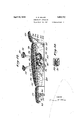
- a spring 28 is attached to each of the arms to hold the toggle in its locked position, and which also tends to hold the head rest against the end of the cabinet when in its lowered position. To lower the head rest a slight pressure is applied to the toggle bracket in a forwardly direction to break the joint. The action of the spring tends to collapse the joint and retain the head rest in the position as shown by the dotted lines in Fig. 12.
- the leg support 29 is hinged to the lower end of the middle portion 21 and is made of less width than the distance between the inside faces of the side pieces 23V so that it can be folded downwardly as shown by the dotted line in Fig. 12. rThe length of the leg rest is longer than the head rest so as to provide a comfortable support for the lower portion of the body.
- the leg rest is supported in its raised position by means of a hinged leg 30 which is attached to the under side of the rest.
- the leg 30 has a spring pressed plunger 31 adapted to register with a hole in a bracket 32 which is attached to the leg rest for the purpose of locking the leg 30 in its operative position.
- Similar spring plungers 33 are inserted in the side pieces 23 to lock the leg support in its folded position.
- the plungers in this case register with pieces 34 which are attached to the bottom of the rest at opposite edges.
- the top boa-rd 35 is upholstered in a suitable manner, likewise the end hinged members.
- the apparatus in this form is easily carried and serves a double purpose for office and out-patient work but it is to be understood that the operating mechanism and rollers may be attached to an oiiice table as well.
- the apparatus comprises two pressure members 36 and 37 which are adapted to engage the chest and abdomen respectively or other parts of the body as the treatment requires.
- the chest pad 36 consists of a piece of resilient material commonly called sponge rubber of about one and one quarter of an inch in thickness. Its length is sutlicient to span the upper part of the chest from points just outside of the arm pits. This pad is made wider at its middle portion than at its ends so that its action is more widely distributed and eifective than if it were uniform in shape throughoutits length. Near each end of the pad is secured a keeper 38 under which the strap passes. This method of attaching the pad to the strap allows the pad to be slidably adjusted relative to the strap.
- the abdominal pad 37 is made of the same material as the chest pad but is comparatively smaller and is shaped so that its upper end will conform with the abdominal surface as outlined by the lower ribs. The shape of this pad is important for the proper distribution of pressure on this part of the body.
- Fig. 1 it will be noted that the straps shown thereon are plain single straps but I have found from experience that a strap made in the manner as shown in Figs. 9 and 10 is preferable. However, either style may be used.
- the center portion 39 is in the form of a long loop which is provided at one end with a. buckle 40 of the toggle type which requires no holes in the strap.
- To each of the looped ends are attached short single straps 41 having snap hooks 43 attached thereto.
- Straps made up in this manner have a double advantage in that the slack of the strap may be taken up by pulling upwardly on the top course of the strap without disturbing the position of the pad when once properly located on the body.
- the lever is connected to the snap hook 43 and 'linkv46 of the roller strap47 as illustrated in F ig. 9.
- the lever is held in one hand of the operator and when pressed downwardly produces tension on the strap without disturbing the buckle adjustment thus regulating the pressure on the pad atwill.
- the strap and pad may be moved to another position while the machineis operating without readjusting the buckle.
- brackets 48 betWeenWhi-ch rollers 49 are mou-nted.
- the brackets are designedso astov bring the rollers outside and free of the edge of the cabinet and yet not. protrudeV to such an extent that they will.. interfere with the operator whenthe apparatus. is applied to an ofce table.
- the bracket is preferably made in one piece with arms 50 at its ends and an intermediate arm ⁇ 5l.
- the rollers are rotatably mounted on a fixed shaft52 which is carried by the bracket arms. This permits the rollersto rotate in opposite directions. Wood is preferred material for' the rollers.
- the operating mechanism' is comparatively simple indesign andcomprises a motor 53, a
- the vertical or driven shaft 56 of the speed gear extendsy through the gear casing 57, and the driving crank 5S is keyed to the shaft: as shown in Fig. 4.
- the motor and speed gear are mounted on aV bed Vplate 59 which is adapted to be securedto the underside ofthe top board 35 of the cabinet, or itl may be attached to members of an office table by means of suitable connections.
- the bed plate is of sufficient thickness to prevent springing and disalignment of the moving parts.
- the speed gear is spaced from the bed plates by means of hollow pieces 60 through which bolts (lpass to secure the speed gear to the bed plate.
- rocker arms 62 and 63 which are mounted on wrist pins 64 secured to the bed plate.
- a washer 65 and pin 66. holds the arm in place on the wrist pin.
- a driving link 67' connects the crank arm 58 to the rocker arml 62 and rocker63is connected to rocker 62 by means of a cross connecting link 68 after the manner as shown in Figs. 3 and 4.
- To the rocker arms are attachedpivotally mountedmembers G9, 70, 7l and 72 having hooked ends which provide the connections between the roller straps 47 and the driving mechanism.
- Means forizi, brication are provided for all ⁇ the moving parts.
- a rotatable member 74 On the extension of the worm shaft 73 is attached a rotatable member 74 having an arm 75 which is eccentric with the axis of the worm shaft for the purpose of connecting the vibration strap 7 6V as shown in Fig. 11. It will be obvious that the worm shaft 73 will rotate at the same rate of speed as'the motor,
- rlhe rockerl arm 63 is cross connected to rocker 62 in such a manner so that the hooks 69'and 71.will be moved alternately to and from each other simultaneously which produces a corresponding pulling and releasing action of the straps attached to the hooks. 'A similar action will be imparted to the straps attached to hooks 70 and 72. It will be obvious that when hooks 69 and 71 are being drawn toward each other that hooks 7 O and 72 will move in the Y opposite direction. Thus the motion imparted to the two different sets ofv straps will be of an alternating order which will produce a'lternatin pressures on the body by means of the pa s.
- rollers 49 have been made'suiiiciently long so as to allow the pads 36 and, 37 to-be placed at different distances apart, and for that reason the hooks have been pivotally attached to the rocker arms to allow of their alignment with the straps.
- Thel length'of the rollers also provides for the longitudinal back and forth creeping action ofthe straps over the rollers due to the angular relation of the straps to the axis of the. rollers which in some cases may be considerable,”depending upon the position of the pads on the body.
- angular lines of pull on the straps will intersect each other at a point 78 substantially on the center line of the machine and that the lines of pull diverge outwardly from this point toward the rollers and upwardly. over the top of the machine.
- pads 36 and 87 are positioned on the body in spaced relation toeach other a downward and forward motion is imparted to pad 86 and a downward and backward motion is imparted to pad 37.
- the term forward being considered as in the direction of the feet of the patient lying on the support, and backward being considered as in the direction of the head of the patient. This motion is particularly useful in the performance of certain treatments as applied to the chest and abdomen.
- the patient When using the vibrating apparatus the patient is placed in the position desired by the operator.
- the end 79 of the strap 76 is buttoned over the eccentric 7 5 and the other end is taken over the roller 49 at the edge of the table and brought into contact with the body of the patient while the operator holds in his hand the free end of the strap and applies tension thereto.
- rIhe action of the rapidly revolving eccentric thus imparts to the body a vibrating motion, the vibration being equivalent to the speed of the motor which is about 1700 R. P. M.
- the vibrator may be used singly or in combination with the other straps if so desired.
- a therapeutic apparatus comprising asupport for a body; a plurality of straps operatively disposed above said support and adapted to engage spaced portions of the body, means located under said support to alternately reciprocate said straps, said means comprising a motor, a speed reducing gear driven by the motor, rocker arms positioned on opposite sides of said gear, a crank driven by said gear, means connecting said crank and one of said rocker arms and means connecting said rocker arms, whereby one of said rocker arms is operated directly by said crank and the other of said rocker arms is operated through the intermediary of the directlyy operated rocker arm.
- a therapeutic apparatus comprising a support for a body; a plurality of straps having pads connected thereto operatively disposed above said support and adapted to engage spaced portions of the body, means located under said support to alternately reciprocate said straps and said pads, said means comprising a motor, a speed reducing gear driven by the motor, rocker arms positioned on opposite sides of said gear, a crank driven by said gear, a driving link connecting said crank and one of said rocker arms, a cross link connecting said rockers, and hooks pivotally connected to said rockers for attaching said straps thereto.
- a therapeutic apparatus comprising a support for a body; a plurality of straps having pads connected thereto operatively disposed above said support and adapted to engage spaced portions of the body, rollers positioned at the sides of said support over which said straps pass to the underside of the support, means located under said support to alternately reciprocate said straps and said pads, said means comprising a motor, a speed reducing gear driven by the motor, rocker arms positioned on the opposite sides of said gear, a crank driven by said gear, a driving link connecting said crank and the end of onefof said rocker arms, a cross link connecting the diagonally opposite ends of said rocker arms, and pivoted connections on said rockers for attaching said straps thereto.
- a portable support for a body comprising a shallow box-like middle portion having hinged end members attached thereto to form extensions to the middle port-ion, straps operatively disposed above said support and adapted to engage spaced portions of the body, mechanism located inside of the middle portion of said support to reciprocate said straps to produce alternating pressures on the body, said mechanism comprising a motor, a speed reducing gear driven by the motor, rocker arms positioned on opposite sides of said gear, a crank driven by said gear, means connecting said crank and one of said rocker arms and means connecting said rocker arms, whereby one of said rocker arms is operated directly by said crank and the other of said rocker arms is operated through the intermediary of the directly operated rocker arm.
- a therapeutic apparatus comprising a box-like support for a body; a plurality of straps having pads connected thereto operatively disposed above said support and adapted to engage spaced portions of the body, mechanism located inside of said support to reciprocate said straps and said pads to produce alternating pressures'on the body, said um, lah
- a support having spaced side pieces of greater heightaat one end than at the other end, a top piece connecting the two side pieces at their top edges, a bottom piece connecting the side pieces at their lower edges, a hinged head rest attached to said top piece andadapted to swing downwardly against the ends of said side pieces, means to support said head rest in its raised position, a leg support hinged to the forward end of said top piece and adapted to swing downwardly and under said top piece, and means toI support the leg rest in its raised position.
- a therapeutic apparatus comprising a portable support for a body; straps having pads connected thereto operatively disposed above said support and adapted to engage spaced portions of the body, mechanism lo-V cated inside of said support to reciprocate said straps and said pads to produce alternating pressures on the body, said support hav-- ing a shallow box-like middle portion with open ends and an inclined top, a swinging head rest attached to one end of said top, a swinging leg rest attached to the other end of said top, means to support said rests V in their raised positions and means to retain said 'rests in their inoperative positions, said leg rest being of greater length but of less width than said head rest so as to swing downwardly and under the top of said support, the top of said middle portion and said swinging rests being covered with resilient material to form cushions.
- a therapeutic apparatus comprising a portable support for a body; straps having pads connected thereto operatively disposed above said support and adapted to engage spaced portions of the body, said support embodying a shallow,l box-like middle portion enclosing a mechanism adapted to reciprocate said straps and said pads to produce alternating pressures on the body, openings in the sides of said boX, brackets positioned in said openings and carrying rollers over which said straps pass tothe inside of the boX and connect with said mechanism, said brackets being secured to the top member of the box and adapted to support fixed shafts on which said rollers revolve, said rollers being of greater length than the width of said straps to allow for longitudinal creep and adjust- Y ment of the straps.
- a therapeutic apparatus comprising a support for a body; a plurality of straps having pads slidably connected thereto operasignature.
Landscapes
- Health & Medical Sciences (AREA)
- Epidemiology (AREA)
- Pain & Pain Management (AREA)
- Physical Education & Sports Medicine (AREA)
- Rehabilitation Therapy (AREA)
- Life Sciences & Earth Sciences (AREA)
- Animal Behavior & Ethology (AREA)
- General Health & Medical Sciences (AREA)
- Public Health (AREA)
- Veterinary Medicine (AREA)
- Percussion Or Vibration Massage (AREA)
Description
April 19, 1932. c. E. MILLER THERAPEUTIC APPARATUS 5 Sheets-Sheet l Filed March 18, 1930 NM NVQ INVENTOR April 19, 1932. c. E. MILLER THERAPEUTIC APPARATUS Filed Mroh 18, 1930 5 Sheets-Sheet 2 INVENTOR Filed March 18, 1930 5 Sheets-Sheet 5 INVENTOR April 19, 1932- c. E; MILLER 1,854,713
THERAPEUTIC APPARATUS Filed March 18, 1 950 5 Sheets-Sheet 4 INVENTOR April 19,1932.
c. E. MILLER THERAPEUTIC .APPARATUS 5 Sheets-Sheet 5 Filed March 18, 1930 km2 f Patented Apr. 19, 1932 UNITED srAres CALVIN E. MILLER, F BETHLEHEM, PENNSYI'JVANIA THERAPEUTIC APPARATUS Application filed. March 18, 1930. Serial `No. 436,802.,
This invention relates to therapeutic apparatus, such as used by osteopathic phys1- cians or others administering mechanical.
February 25, 1929, but of more simple con struction.
Another object of this invention 1s; to provide an apparatus ofV this character which Will' be highly efficient, have few parts, beV economical to manufacture and practicallyA trouble and service free.
Generally' speaking, this apparatus comprises a cabinet-like support fora recumbent'v body which houses a. power-driven mechanism for imparting a pulling action to straps.
55 to which are attached. resilient pads adapted to engage the chest and abdomen orl other parts of the body as the case maybe. The functions of the body engaging members are, to impart puhiatingpressures to. the body' J in positive alternating relation to each other.;
An auxiliary mechanism is provided to impart rapid vibrations by means of another strap which may be applied to various portionsV of the body as desired.
This apparatus, by its. pumping action on the body, is particularly adapted to increase.
the normal flow or movement. ofthe lymph from the tissues and organsl ofthe body into the blood stream and return the venus blood i?) back to the heart quickly and supply fresh nutritive lymph. However, it is not limited to this function alone, as it is well adapted to treat the spine or other parts of the body.
Vshen used to increase the flow of the lymph.
the patient` lies on his back but when used for spinal Vor other treatment the body is positioned-1 accordingly on the support.
vThis apparatus is adapted to be embodied into a. portable cabinet having folding ends or it may be attached to any of the standard oflice treating tables, by means of special attachments adapted to the design of the respective tables, but for uniformity I have chosen to' illustrate and describe the portable species.
y The novel features will be more fully understood from the following description and claims taken with thedirawings, in which:
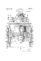
Fig. 1 is a perspective view of the apparatus showing the support for` the body, the folding end members and therelation of the body engaging members; i
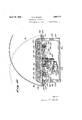
Fig; 2 isA a cross sectional view taken through the support on line 2-2 of Fig. 3 showing its box-like construction and the actuating mechanism therein,
Fig. 3' shows the planV of the operating mechanism wheny viewed from the-under side of the machine. Y
Fig. 4' is a plan view of the mechanism as seen in Fig. Shut viewed looking down and in the opposite direction to that of Fig. 3 with the bed' plate removed.
Fig.` iis a plan view of the abdominal. pad.
Fig'.` 6 is a detailed view of a rocker arm and hook assembly. f
Fig. 7 is a plan view of theA chest pad.
Fig. 8 isa sectional view of the speed re ducingy gear shown in Fig. 3.
Fig. 9 shows a pad and strap assembly in combination with a hand-operated adjusting and tensioning device.
Fig. l0 is a-n enlarged view showing a preferred form of make-up of the strap mem` bers.
Fig. 11 is a sectional view similar to Fig. 2 but shows the manner in which the vibrating strap is operated and. applied.
Fig. 12 is a section taken longitudinally through the apparatus and; shows the de-v tails of the cabinet and the folding end members.
Fig. 13 is a detail of the locking device for retaining the leg support in its closed position and for retaining the supporting member in its opened or operative position.
Referring to Fig. 1, numeral 2O indicates generally an upholstered cabinet which forms a support for a recumbe'nt body, and is adapted to house the mechanism which operates the straps and pads. The cabinet comprises a rectangular boX shaped middle portion 21 which contains the operating mechanism. A hinged head rest 22 is attached to the upper end of the support and is adapted to fold downwardly against the ends of the side pieces 23 to close the open end of the cabinet when not in use. The head restis supported in its raised position by means of a collapsible toggle bracket 24 attached to the under side of the head rest and the bottom board 25 of the cabinet. The toggle comprises two hinged arms pivotally attache-d to brackets 26 and 27. The intermediate ends of the arms are provided with hinged jaws adapted to abut each other when the arms are carried past the dead center of the bracket, which constitutes a point on a line intersecting the pivoted joints at the ends of the arms. Then the jaws of the two arms are brought together, no further outward movement of the arms can take place, thus forming a rigid and self-locking support for the head rest when it is in raised position. A spring 28 is attached to each of the arms to hold the toggle in its locked position, and which also tends to hold the head rest against the end of the cabinet when in its lowered position. To lower the head rest a slight pressure is applied to the toggle bracket in a forwardly direction to break the joint. The action of the spring tends to collapse the joint and retain the head rest in the position as shown by the dotted lines in Fig. 12.
The leg support 29 is hinged to the lower end of the middle portion 21 and is made of less width than the distance between the inside faces of the side pieces 23V so that it can be folded downwardly as shown by the dotted line in Fig. 12. rThe length of the leg rest is longer than the head rest so as to provide a comfortable support for the lower portion of the body. The leg rest is supported in its raised position by means of a hinged leg 30 which is attached to the under side of the rest. The leg 30 has a spring pressed plunger 31 adapted to register with a hole in a bracket 32 which is attached to the leg rest for the purpose of locking the leg 30 in its operative position. Similar spring plungers 33 are inserted in the side pieces 23 to lock the leg support in its folded position. The plungers in this case register with pieces 34 which are attached to the bottom of the rest at opposite edges.
The top boa-rd 35 is upholstered in a suitable manner, likewise the end hinged members. The apparatus in this form is easily carried and serves a double purpose for office and out-patient work but it is to be understood that the operating mechanism and rollers may be attached to an oiiice table as well.
The apparatus comprises two pressure members 36 and 37 which are adapted to engage the chest and abdomen respectively or other parts of the body as the treatment requires.
As shownin Fig. 7, the chest pad 36 consists of a piece of resilient material commonly called sponge rubber of about one and one quarter of an inch in thickness. Its length is sutlicient to span the upper part of the chest from points just outside of the arm pits. This pad is made wider at its middle portion than at its ends so that its action is more widely distributed and eifective than if it were uniform in shape throughoutits length. Near each end of the pad is secured a keeper 38 under which the strap passes. This method of attaching the pad to the strap allows the pad to be slidably adjusted relative to the strap. The abdominal pad 37 is made of the same material as the chest pad but is comparatively smaller and is shaped so that its upper end will conform with the abdominal surface as outlined by the lower ribs. The shape of this pad is important for the proper distribution of pressure on this part of the body.
In Fig. 1 it will be noted that the straps shown thereon are plain single straps but I have found from experience that a strap made in the manner as shown in Figs. 9 and 10 is preferable. However, either style may be used. In the preferred form, the center portion 39 is in the form of a long loop which is provided at one end with a. buckle 40 of the toggle type which requires no holes in the strap. To each of the looped ends are attached short single straps 41 having snap hooks 43 attached thereto.
Straps made up in this manner have a double advantage in that the slack of the strap may be taken up by pulling upwardly on the top course of the strap without disturbing the position of the pad when once properly located on the body. This is possible because the loops at the ends of the central strap 39 permit the looped ends to be brought closer to each other by sliding through the connecting links 44 without moving the pad; secondly, if it desired to distribute the pull of thc strap over a greater portion of the pad, the top course of the strap may be shifted so as to contact with the pad higher up, thus covering the pad to a greater extent than when the upper and lower portion of the strap are parallel or in line with each other.
In case it is desired to make repeated changes of'position of a pad without stopping the motor, the lever is connected to the snap hook 43 and 'linkv46 of the roller strap47 as illustrated in F ig. 9. The lever is held in one hand of the operator and when pressed downwardly produces tension on the strap without disturbing the buckle adjustment thus regulating the pressure on the pad atwill. When the` pressure on the` lever is releasedthe strap and pad may be moved to another position while the machineis operating without readjusting the buckle.
At each side and underneath the top of thesupport or'tableare secu-red brackets 48 betWeenWhi-ch, rollers 49 are mou-nted. The brackets are designedso astov bring the rollers outside and free of the edge of the cabinet and yet not. protrudeV to such an extent that they will.. interfere with the operator whenthe apparatus. is applied to an ofce table. The bracket is preferably made in one piece with arms 50 at its ends and an intermediate arm` 5l. The rollers are rotatably mounted on a fixed shaft52 which is carried by the bracket arms. This permits the rollersto rotate in opposite directions. Wood is preferred material for' the rollers.
The operating mechanism' is comparatively simple indesign andcomprises a motor 53, a
speed'reduci'ng gear 54, a flexible couplingv 55 connecting the shafts of the motor and the speedgear. The vertical or driven shaft 56 of the speed gear extendsy through the gear casing 57, and the driving crank 5S is keyed to the shaft: as shown in Fig. 4. The motor and speed gear are mounted on aV bed Vplate 59 which is adapted to be securedto the underside ofthe top board 35 of the cabinet, or itl may be attached to members of an office table by means of suitable connections. The
bed plate is of sufficient thickness to prevent springing and disalignment of the moving parts. The speed gear is spaced from the bed plates by means of hollow pieces 60 through which bolts (lpass to secure the speed gear to the bed plate. YOn opposite sides of the speed gear are positioned rocker arms 62 and 63 which are mounted on wrist pins 64 secured to the bed plate. A washer 65 and pin 66. holds the arm in place on the wrist pin. A driving link 67' connects the crank arm 58 to the rocker arml 62 and rocker63is connected to rocker 62 by means of a cross connecting link 68 after the manner as shown in Figs. 3 and 4. To the rocker arms are attachedpivotally mountedmembers G9, 70, 7l and 72 having hooked ends which provide the connections between the roller straps 47 and the driving mechanism. Means for lui, brication are provided for all `the moving parts.
On the extension of the worm shaft 73 is attached a rotatable member 74 having an arm 75 which is eccentric with the axis of the worm shaft for the purpose of connecting the vibration strap 7 6V as shown in Fig. 11. It will be obvious that the worm shaft 73 will rotate at the same rate of speed as'the motor,
which in this case is about 1700 R. vl). M.,
duce the mostbeneiicial results.
For the purpose of describing the operation of myinvention, it will be assumed that treatment of the chest and abdomen is desired. With the patient in a recumbent position on the table, the pads 36 and 37 are placed in their proper positions, and the straps are attached Vto the actuating mechanism. After this has been done, the slack in each strap is taken up to the desired tension and held in this condition by means of the buckle. On starting the motor, a rotary. motion is imparted to the driving crank 5S through the speed gear, and the driving link G7 connecting the crank to the rocker arm 62 converts the rotary motion of the crank into an oscillating motion of the rocker arm. rlhe rockerl arm 63 is cross connected to rocker 62 in such a manner so that the hooks 69'and 71.will be moved alternately to and from each other simultaneously which produces a corresponding pulling and releasing action of the straps attached to the hooks. 'A similar action will be imparted to the straps attached to hooks 70 and 72. It will be obvious that when hooks 69 and 71 are being drawn toward each other that hooks 7 O and 72 will move in the Y opposite direction. Thus the motion imparted to the two different sets ofv straps will be of an alternating order which will produce a'lternatin pressures on the body by means of the pa s.
It will be noted that the rollers 49 have been made'suiiiciently long so as to allow the pads 36 and, 37 to-be placed at different distances apart, and for that reason the hooks have been pivotally attached to the rocker arms to allow of their alignment with the straps. Thel length'of the rollers also provides for the longitudinal back and forth creeping action ofthe straps over the rollers due to the angular relation of the straps to the axis of the. rollers which in some cases may be considerable,"depending upon the position of the pads on the body.
Referring to Fig. 3, it will be noted that the angular lines of pull on the straps will intersect each other at a point 78 substantially on the center line of the machine and that the lines of pull diverge outwardly from this point toward the rollers and upwardly. over the top of the machine. Obviously, when the pads 36 and 87 are positioned on the body in spaced relation toeach other a downward and forward motion is imparted to pad 86 and a downward and backward motion is imparted to pad 37. The term forward being considered as in the direction of the feet of the patient lying on the support, and backward being considered as in the direction of the head of the patient. This motion is particularly useful in the performance of certain treatments as applied to the chest and abdomen.
When using the vibrating apparatus the patient is placed in the position desired by the operator. The end 79 of the strap 76 is buttoned over the eccentric 7 5 and the other end is taken over the roller 49 at the edge of the table and brought into contact with the body of the patient while the operator holds in his hand the free end of the strap and applies tension thereto. rIhe action of the rapidly revolving eccentric thus imparts to the body a vibrating motion, the vibration being equivalent to the speed of the motor which is about 1700 R. P. M. The vibrator may be used singly or in combination with the other straps if so desired.
It will be seen by the foregoing that I have provided a. therapeutic apparatus which will automatically perform treatments in a manner which by actual practice by hand have proven most effective. Furthermore, so far as I am aware, no apparatus of this nature has heretofore been devised which is adapted to be easily carried or transported for use outside of the oiiice. Obviously, this novel feature adds greatly to its usefulness as it can be easily brought to the patient who is too ill to make an oilice call. This feature alone greatly enhances its value.
lVhile I have shown my invention in but one form it will be obvious to those skilled in the art that it is not so limited, but is susceptible of various changes and modifications without departing from the spirit thereof, and I desire, therefore, that only such limitations shall'be placed thereupon as are imposed by the prior art or as are specifically set forth in the appended claims.
I claim:
l. In a therapeutic apparatus comprising asupport for a body; a plurality of straps operatively disposed above said support and adapted to engage spaced portions of the body, means located under said support to alternately reciprocate said straps, said means comprising a motor, a speed reducing gear driven by the motor, rocker arms positioned on opposite sides of said gear, a crank driven by said gear, means connecting said crank and one of said rocker arms and means connecting said rocker arms, whereby one of said rocker arms is operated directly by said crank and the other of said rocker arms is operated through the intermediary of the directlyy operated rocker arm.
2. In a therapeutic apparatus comprising a support for a body; a plurality of straps having pads connected thereto operatively disposed above said support and adapted to engage spaced portions of the body, means located under said support to alternately reciprocate said straps and said pads, said means comprising a motor, a speed reducing gear driven by the motor, rocker arms positioned on opposite sides of said gear, a crank driven by said gear, a driving link connecting said crank and one of said rocker arms, a cross link connecting said rockers, and hooks pivotally connected to said rockers for attaching said straps thereto.
3. In a therapeutic apparatus comprising a support for a body; a plurality of straps having pads connected thereto operatively disposed above said support and adapted to engage spaced portions of the body, rollers positioned at the sides of said support over which said straps pass to the underside of the support, means located under said support to alternately reciprocate said straps and said pads, said means comprising a motor, a speed reducing gear driven by the motor, rocker arms positioned on the opposite sides of said gear, a crank driven by said gear, a driving link connecting said crank and the end of onefof said rocker arms, a cross link connecting the diagonally opposite ends of said rocker arms, and pivoted connections on said rockers for attaching said straps thereto.
d. Ina therapeutic apparatus, a portable support for a body, comprising a shallow box-like middle portion having hinged end members attached thereto to form extensions to the middle port-ion, straps operatively disposed above said support and adapted to engage spaced portions of the body, mechanism located inside of the middle portion of said support to reciprocate said straps to produce alternating pressures on the body, said mechanism comprising a motor, a speed reducing gear driven by the motor, rocker arms positioned on opposite sides of said gear, a crank driven by said gear, means connecting said crank and one of said rocker arms and means connecting said rocker arms, whereby one of said rocker arms is operated directly by said crank and the other of said rocker arms is operated through the intermediary of the directly operated rocker arm.
5. vIn a therapeutic apparatus comprising a box-like support for a body; a plurality of straps having pads connected thereto operatively disposed above said support and adapted to engage spaced portions of the body, mechanism located inside of said support to reciprocate said straps and said pads to produce alternating pressures'on the body, said um, lah
support having spaced side pieces of greater heightaat one end than at the other end, a top piece connecting the two side pieces at their top edges, a bottom piece connecting the side pieces at their lower edges, a hinged head rest attached to said top piece andadapted to swing downwardly against the ends of said side pieces, means to support said head rest in its raised position, a leg support hinged to the forward end of said top piece and adapted to swing downwardly and under said top piece, and means toI support the leg rest in its raised position. i
6. In a therapeutic apparatus comprising a portable support for a body; straps having pads connected thereto operatively disposed above said support and adapted to engage spaced portions of the body, mechanism lo-V cated inside of said support to reciprocate said straps and said pads to produce alternating pressures on the body, said support hav-- ing a shallow box-like middle portion with open ends and an inclined top, a swinging head rest attached to one end of said top, a swinging leg rest attached to the other end of said top, means to support said rests V in their raised positions and means to retain said 'rests in their inoperative positions, said leg rest being of greater length but of less width than said head rest so as to swing downwardly and under the top of said support, the top of said middle portion and said swinging rests being covered with resilient material to form cushions.
7. In a therapeutic apparatus comprising a portable support for a body; straps having pads connected thereto operatively disposed above said support and adapted to engage spaced portions of the body, said support embodying a shallow,l box-like middle portion enclosing a mechanism adapted to reciprocate said straps and said pads to produce alternating pressures on the body, openings in the sides of said boX, brackets positioned in said openings and carrying rollers over which said straps pass tothe inside of the boX and connect with said mechanism, said brackets being secured to the top member of the box and adapted to support fixed shafts on which said rollers revolve, said rollers being of greater length than the width of said straps to allow for longitudinal creep and adjust- Y ment of the straps.
8. In a therapeutic apparatus comprising a support for a body; a plurality of straps having pads slidably connected thereto operasignature.
CALVIN E. MILLER.
Priority Applications (1)
| Application Number | Priority Date | Filing Date | Title |
|---|---|---|---|
| US436802A US1854713A (en) | 1930-03-18 | 1930-03-18 | Therapeutic apparatus |
Applications Claiming Priority (1)
| Application Number | Priority Date | Filing Date | Title |
|---|---|---|---|
| US436802A US1854713A (en) | 1930-03-18 | 1930-03-18 | Therapeutic apparatus |
Publications (1)
| Publication Number | Publication Date |
|---|---|
| US1854713A true US1854713A (en) | 1932-04-19 |
Family
ID=23733882
Family Applications (1)
| Application Number | Title | Priority Date | Filing Date |
|---|---|---|---|
| US436802A Expired - Lifetime US1854713A (en) | 1930-03-18 | 1930-03-18 | Therapeutic apparatus |
Country Status (1)
| Country | Link |
|---|---|
| US (1) | US1854713A (en) |
Cited By (4)
| Publication number | Priority date | Publication date | Assignee | Title |
|---|---|---|---|---|
| US3381538A (en) * | 1965-05-14 | 1968-05-07 | Kenneth R. Runde | Vibration apparatus |
| US20060009720A1 (en) * | 2004-07-07 | 2006-01-12 | Hung-Chun Chung | Abdominal fitness equipment installable on a chair |
| US10639234B2 (en) * | 2015-10-16 | 2020-05-05 | Zoll Circulation, Inc. | Automated chest compression device |
| US10682282B2 (en) | 2015-10-16 | 2020-06-16 | Zoll Circulation, Inc. | Automated chest compression device |
-
1930
- 1930-03-18 US US436802A patent/US1854713A/en not_active Expired - Lifetime
Cited By (6)
| Publication number | Priority date | Publication date | Assignee | Title |
|---|---|---|---|---|
| US3381538A (en) * | 1965-05-14 | 1968-05-07 | Kenneth R. Runde | Vibration apparatus |
| US20060009720A1 (en) * | 2004-07-07 | 2006-01-12 | Hung-Chun Chung | Abdominal fitness equipment installable on a chair |
| US10639234B2 (en) * | 2015-10-16 | 2020-05-05 | Zoll Circulation, Inc. | Automated chest compression device |
| US10682282B2 (en) | 2015-10-16 | 2020-06-16 | Zoll Circulation, Inc. | Automated chest compression device |
| US11666506B2 (en) | 2015-10-16 | 2023-06-06 | Zoll Circulation, Inc. | Automated chest compression device |
| US20230277412A1 (en) * | 2015-10-16 | 2023-09-07 | Zoll Circulation, Inc. | Automated chest compression device |
Similar Documents
| Publication | Publication Date | Title |
|---|---|---|
| US2427053A (en) | Combination chair and table for body massaging and muscle manipulation | |
| US2660999A (en) | Spinal column aligning table | |
| US2206038A (en) | Orthopedic apparatus | |
| US2359933A (en) | Massage table | |
| US2052656A (en) | Massage machine | |
| US1529872A (en) | Automatic treating table | |
| US1953424A (en) | Therapeutic apparatus | |
| US1508892A (en) | Exercising and spine-stretching apparatus | |
| US2840072A (en) | Massage bed | |
| US1854713A (en) | Therapeutic apparatus | |
| US1929107A (en) | Massaging machine | |
| US2703080A (en) | Table with posture correction apparatus | |
| US2139166A (en) | Universal mechano-surgical apparatus | |
| US1537464A (en) | Ointment chirapractor | |
| US1499013A (en) | Chiropractic table | |
| US951515A (en) | Attachment for physician's operating-tables. | |
| US1621931A (en) | Desk-sanding machine | |
| US1121795A (en) | Fracture apparatus. | |
| US2756743A (en) | Exercising machine | |
| US2441394A (en) | Vibration and massage apparatus | |
| US1899544A (en) | Vibratory apparatus | |
| US1786047A (en) | Mechanical hair gland and nerve agitator | |
| US1868452A (en) | Vibratory apparatus | |
| US97744A (en) | Improved apparatus for treating diseases by mechanical movement | |
| US1459953A (en) | Osteopathic table |