US18547A - Method of operating scroll-saws - Google Patents
Method of operating scroll-saws Download PDFInfo
- Publication number
- US18547A US18547A US18547DA US18547A US 18547 A US18547 A US 18547A US 18547D A US18547D A US 18547DA US 18547 A US18547 A US 18547A
- Authority
- US
- United States
- Prior art keywords
- saw
- saws
- belts
- operating
- operating scroll
- Prior art date
- Legal status (The legal status is an assumption and is not a legal conclusion. Google has not performed a legal analysis and makes no representation as to the accuracy of the status listed.)
- Expired - Lifetime
Links
- 238000010276 construction Methods 0.000 description 10
- 241000763859 Dyckia brevifolia Species 0.000 description 6
- 210000003414 Extremities Anatomy 0.000 description 2
- 230000000414 obstructive Effects 0.000 description 2
- 238000007493 shaping process Methods 0.000 description 2
Images
Classifications
-
- B—PERFORMING OPERATIONS; TRANSPORTING
- B23—MACHINE TOOLS; METAL-WORKING NOT OTHERWISE PROVIDED FOR
- B23D—PLANING; SLOTTING; SHEARING; BROACHING; SAWING; FILING; SCRAPING; LIKE OPERATIONS FOR WORKING METAL BY REMOVING MATERIAL, NOT OTHERWISE PROVIDED FOR
- B23D49/00—Machines or devices for sawing with straight reciprocating saw blades, e.g. hacksaws
- B23D49/007—Jig saws, i.e. machine saws with a vertically reciprocating narrow saw blade chucked at both ends for contour cutting
-
- Y—GENERAL TAGGING OF NEW TECHNOLOGICAL DEVELOPMENTS; GENERAL TAGGING OF CROSS-SECTIONAL TECHNOLOGIES SPANNING OVER SEVERAL SECTIONS OF THE IPC; TECHNICAL SUBJECTS COVERED BY FORMER USPC CROSS-REFERENCE ART COLLECTIONS [XRACs] AND DIGESTS
- Y10—TECHNICAL SUBJECTS COVERED BY FORMER USPC
- Y10T—TECHNICAL SUBJECTS COVERED BY FORMER US CLASSIFICATION
- Y10T83/00—Cutting
- Y10T83/687—By tool reciprocable along elongated edge
- Y10T83/705—With means to support tool at opposite ends
- Y10T83/7055—And apply drive force to both ends of tool
- Y10T83/706—By flexible drive means
Definitions
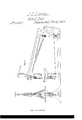
- my invention consists in straining the saw by means of two belts, one of which connects the upper end of the saw and the other the lower end of the saw to the opposite extremities of a dist-ant double lever by the alternate movements of which the saw is operated: by which mode of construction ample space is provided around the saw for the shaping and handling of all descriptions of work.
- Figure l is a front elevation of the machine and Fig. 2 a side elevation, and where the same parts appear in both drawings they are indicated by the same letters.
- Figs. l and 2 A A is the table or platform upon which the work or stuff to be shaped or sawn is placed and B is the saw blade, which for the purposes of scroll work is usually made very narrow so as to turn the quick curves and corners ot such work, and is attached to the buckles O, C by means of catch pins or pinch screws, in the usual manner.
- To the buckles O and O are also attached the belts D D and D D',
- the lever F F being operated by the pitman Gr, which is attached by a pin or joint to the arm H, and by drawing alternately the upper and lower belts D D and D D operates the saw B. To keep the saw B in proper 18,547, dated November 3, 1857.
Description
description thereof, reference being had to which belts pass around the pulleys E and UNITED sTATEs PATENT oEEIcE.
JOHN L. LAWTON, OF BALTIMORE, MARYLAND.
METHOD OF OPERATING SGROLL-SAWS.
Specification of Letters Patent No.
To all whom it may concern.'
Be it known that I, J oHN L. LAwToN, of the city of Baltimore and State of Maryland, have invented a new and useful Improvement in the Construction and Mode of Operating Scroll-Saws; and I do hereby declare that the following is a full and exact the accompanying drawings and to the letters of reference marked thereon.
The nature of my invention consists in straining the saw by means of two belts, one of which connects the upper end of the saw and the other the lower end of the saw to the opposite extremities of a dist-ant double lever by the alternate movements of which the saw is operated: by which mode of construction ample space is provided around the saw for the shaping and handling of all descriptions of work.
To enable others skilled in the art to make and use my invention I will proceed to describe its construction and operation.
In the accompanying drawings, Figure l is a front elevation of the machine and Fig. 2 a side elevation, and where the same parts appear in both drawings they are indicated by the same letters.
' In Figs. l and 2 A A is the table or platform upon which the work or stuff to be shaped or sawn is placed and B is the saw blade, which for the purposes of scroll work is usually made very narrow so as to turn the quick curves and corners ot such work, and is attached to the buckles O, C by means of catch pins or pinch screws, in the usual manner. To the buckles O and O are also attached the belts D D and D D',
E, back to the double armed lever F F. The lever F F being operated by the pitman Gr, which is attached by a pin or joint to the arm H, and by drawing alternately the upper and lower belts D D and D D operates the saw B. To keep the saw B in proper 18,547, dated November 3, 1857.
position I cause the buckles O and C to slide upon the square guide posts L L, (a port-ion of which is removed above the table in order to give free space at the saw for the shifting of the material while being cut). For the purpose of straining the saw I attach the upper pulley B to the slider M and raise and lower it, so as to tighten or slacken the belts, by the lever N, and when the pulley is suliiciently elevated to give the `necessary tension to the saw blade I place the adjustable screw block O between the slider M and the stud or bracket P, and by this means any degree of tension that may be required can be given to the saw.
When the saw is not in operation the screw block O should be removed so as to slack up the saw blade and the belts.
The advantages ot this mode of construction and operation are important. 1st, the machine is completely free from obstruction for all ordinary purposes, as the distance from the saw B to the back post R is only limited by convenience. 2nd the absence of a saw gate and all the moving parts being very light permits of the saw being operated at a very rapid speed, when' compared with the ordinary gate machines, and the moving parts being light, the vexpenditure of power in overcoming the inertia of the machine is but small, which is an economical result.
Having thus explained the nature, construction and mode of operation of my improved sawing machine what I claim therein as my invention and desire to secure by Letters Patent is- The method of operating the saw by means of the belts and back levers substantially as described.
JNO. L. LAVTON.
Vitnesses:
JACOB B. THOMAS, J. E. THOMAS.
Publications (1)
| Publication Number | Publication Date |
|---|---|
| US18547A true US18547A (en) | 1857-11-03 |
Family
ID=2081953
Family Applications (1)
| Application Number | Title | Priority Date | Filing Date |
|---|---|---|---|
| US18547D Expired - Lifetime US18547A (en) | Method of operating scroll-saws |
Country Status (1)
| Country | Link |
|---|---|
| US (1) | US18547A (en) |
-
0
- US US18547D patent/US18547A/en not_active Expired - Lifetime
Similar Documents
| Publication | Publication Date | Title |
|---|---|---|
| US18547A (en) | Method of operating scroll-saws | |
| US16435A (en) | Sawing-machine | |
| US19654A (en) | sbmple | |
| US13305A (en) | Sawing-machine | |
| US15814A (en) | Machine eob | |
| US13531A (en) | Machine for sawing hoops | |
| US10778A (en) | Circular sawing machine | |
| US14471A (en) | Machine fob sawing marble ikt taper eorm | |
| US16062A (en) | Method of hanging r-eciprocating saws | |
| US19906A (en) | Sawing-machine | |
| US18402A (en) | Device fob guiding the logs in sawing given curvatures | |
| US15913A (en) | Simon ingersoll | |
| US13916A (en) | Machine for sawing marble | |
| US93138A (en) | Improvement in gig sawing-machine | |
| US14765A (en) | Shingle-machine | |
| US11708A (en) | Loren j | |
| US14413A (en) | Method of straining mtjley-saws | |
| US16742A (en) | Shingle-machine | |
| US14658A (en) | Machine foe | |
| US24564A (en) | Crosscut-sawing machine | |
| US19644A (en) | Sawing-machibte | |
| US15216A (en) | Machine fob sawing fellies | |
| US14656A (en) | Straining marble-saws | |
| US12337A (en) | Sawing-machine | |
| US15026A (en) | Sawibtg-machine |