US1854670A - ridder - Google Patents
ridder Download PDFInfo
- Publication number
- US1854670A US1854670A US1854670DA US1854670A US 1854670 A US1854670 A US 1854670A US 1854670D A US1854670D A US 1854670DA US 1854670 A US1854670 A US 1854670A
- Authority
- US
- United States
- Prior art keywords
- piston
- chamber
- rings
- valve
- casing
- Prior art date
- Legal status (The legal status is an assumption and is not a legal conclusion. Google has not performed a legal analysis and makes no representation as to the accuracy of the status listed.)
- Expired - Lifetime
Links
- 239000012530 fluid Substances 0.000 description 6
- 238000005192 partition Methods 0.000 description 5
- 230000004048 modification Effects 0.000 description 4
- 238000012986 modification Methods 0.000 description 4
- 101150027068 DEGS1 gene Proteins 0.000 description 3
- 238000012856 packing Methods 0.000 description 3
- 238000010276 construction Methods 0.000 description 2
- 230000001105 regulatory effect Effects 0.000 description 2
- 239000007787 solid Substances 0.000 description 2
- 241000234671 Ananas Species 0.000 description 1
- 239000000956 alloy Substances 0.000 description 1
- 229910045601 alloy Inorganic materials 0.000 description 1
- 238000013459 approach Methods 0.000 description 1
- 238000002485 combustion reaction Methods 0.000 description 1
- 238000001816 cooling Methods 0.000 description 1
- 230000007717 exclusion Effects 0.000 description 1
- 238000010438 heat treatment Methods 0.000 description 1
- 239000002184 metal Substances 0.000 description 1
- 239000000203 mixture Substances 0.000 description 1
- 238000003466 welding Methods 0.000 description 1
Images

Definitions
- My invention relates to rotary machines
- the piston may be cast or forged integral with the ring or it may be screwed, welded, or otherwise secured to the ring. In this manner not only a very rugged construction of the rotor is obtained, but the weight of the machine is also greatly reduced, as the usual solid rotor is replaced by the comparatlvely small and light ring.
- I provide a casing consistin of two separate parts which are connecte by sultable means and, when connected, form an annular piston chamber in which the piston or pistons are fitted to rotate about the axis of the machine and ⁇ are connected with two parallel rings.
- One of the rings is connected with the other ring by the piston at one side, and with a disc which is keyed onto the shaft, at the other side.
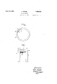
- Fig. 1 is partly an elevation and partly a central verticalsection of my machine
- Fig. 2 is partly a section on the line II-'II ale pointbeyond the pair of cam plate 32,
- the inner and y outer parts 8 and 12 of the. '10A Casln make up together an annular piston cham er 41, the outer part 12 being provided with a pair of standards 35, and the inner part being secured to the outer part by means of a flange 45 and screws 10. From this ange, a cylinder 46 projects inwardly, the outer radius of which is equal to the inner radius of the outer part 12, minus the radial height ⁇ of the piston chamber 41.
- the outer face of the disc 3 is flush with the face of the casing 12.
- the piston may be cast or orged in one with the two rings and 55, or with one of them, or it may be made separately and secured to one, or both, rings by any suitable means, welding, riveting or screwing. In any case it makes a comparatively long and rigid conder 46, whereas in the usual type of engine this space is occupied by the solid rotor.
- My rotor 5, 36, 55 is positively connected with the dise 3 by the screws 4 and the ring 5, so
- a heating or cooling jacket 38 may also be provided for the outer casing 12.
- the engine is equipped with two pistons 36, one of' which onl is shown in Fig. 1, the other being arrange at an angle of 180 degs. with respect to the first piston.
- the annular piston chamber 41 must be divided into two compartments, which is effected by two control slides 23 in suitable recesses of the. casing 12 which, like the pistons 36, are arranged at an .angle of 180 degs. with respect to each other.
- the means for4 supplying the driving fluid to the piston chamber 41 are arranged in the vicinity of the slides 23.
- ports 29 extend to the chamber of a piston valve 27 which is turned down at 37 in conformity with the ports 29,9and 47 are ports extending from the' chamber of the piston valve to the piston chamber 41 in line with the ports 29.
- the ports 29 and 47 are separated by the ull parts of the piston valve 27, but,- when the piston valve is displaced to the right in Fig. 3, each of its turned-down arts connects aport 29- with the correspon ing port 47, and steam is admitted to the chamber 41.
- the chamber 17 and the piston valve 27 are duplicated at the other side of the engine, the second valve 27 being shown in Fig. 1. 13, 13 are two exhaust passages which o en into the'chamber 41 at opposlte sides an are connected with exhaust pipes 14.
- Means may be provided for operatingthe A engine as an internal combustion en ne.
- a chamber 42 is partitioned from the eatshown in Fig. 1 at the right.
- the slides 23 are pre erably made of light metal or alloy, cast hollow as shown in Fi s. 4 and 5 in order to reduce the inertia orces, and are provided with packing strips 24 for their upper and lower faces, and with angular strips 25 at their inner ends which, as shown in Fig.
- the piston valve 27 and 49 is a pin projecting from its other end, the pin 49 and the roller 28 being adapted to cooperate with the cams 34.
- 30 is a spring which is inserted between a shoulder on the piston valve 27 and a washer 48 in the fiange 45, and which tends to hold the roller 28 engaged with the flat face of the cam 32 at the left, Fig. 3, in which position the piston valve breaks the connection of the ports 29 and 47.
- the cams 34 at the left and at the right are staggered with respect to each other so that when the roller 28 is engaged and moved to the left by cam 34 at the left, the pin 49 is permitted to slide down on the descent of the cam 34 at the right. In this manner the valve 27 is never free but is permanentlyheld in positive engagement with one of the cams 34 and with the opposite cam plate32.
- Driving iluid is permanentl admitted to the chamber 17 Vthrough va sultable throttle valve, not shown, and through the port 29 to the piston valve 27.
- the cams 33 on the cam plates 32 have just released the rollers 26 'side of the engine, the second lid 16 being p l the piston valve 27 inwardly against the action of their springs 30, and the turned-down parts 37 ofthe valve 27 register with the ports 29 and 47.
- Fluid is admitted into the piston chamber 41 and moves the pistons 36 in clockwise direction.
- the exhaust passages 13 are permanently open and the exhaust is.
- the slide is retracted by the-correspondin cam 33, and held retracted, until the rear e Ige of the piston has moved past it, whereupon the slide returns into its closing position and a fresh supply of fiuid is admitted bythe piston valve 27 at the right, impartin impetus to the piston until it arrives at t e lower exhaust passage 13.
- the slide 23 at the left is now retracted for permitting the piston to pass, and closed behind the piston, which isI now again in the position illustrated in Fig. 1.
- the second piston obviously performs the same cycle of operations, but distorted at an angle of 180 degs. with respect to the cycle of l the first piston.
- a rotary machine comprising a casing' larger than the outside diameter of said inner part, a flange on said inner part adapted to be secured to said outer part, so that said inner and outer part, when connected, make up an annular iston chamber, a pair of rings which are ree to rotate in said chamber, a piston connected with said rings and packed against the walls of said chamber, a shaft, and means operatively connected with -said rings for transmittingv its rotation to said shaft.
- a rotary machine comprising a casing including an annular piston chamber having fixed walls, a pair of rings which are free to rotate in said chamber, a piston connected with said rings and packed against the walls of said chamber, a shaft, a disc secured on said shaft and extending into lsaid outer casing at the end of said inner casing, and means for connecting said rings with said disc.
- a rotary machine comprising a casing including an annular piston chamber having fixed'walls, a air of rings which are free to rotate in sai chamber, a piston connected with said-rin s and packed against the walls of said cham er, a shaft, means operatively connected with said rings for transmitting its rotation to said shaft, a partition adapted to subdivide said piston chamber, means operatively connected with said rin for advancin and retracting said partitlon in time with tie movements of the piston in said chamber, fluid supply and exhaust means connected with said piston chamber, a valve for regulating the supply of fluid from said supply means to said chamber. and means operatively connected with said rings and including a cam and a spring for operating said valve in time with the movements of said piston and said partition.
Landscapes
- Compressors, Vaccum Pumps And Other Relevant Systems (AREA)
Description
2 Sheets-Sheet I O. RIDDER ROTARY ENGINE April 19, 1932.
ptil 19, 1932. I y Q RIDDER 1,854,670
ROTARY ENGINE x Filed Jan. 5, 1950 2. Sheets-Sheet 2 Patented Apr. 199, 1932 UNITEo s'rATEsPATENT OFI-rca o'rtroI ananas., or Bumeran, annum v abrazar nnenrn Application iled January 3, 41980, Serial No. 418,857, and in Germany'J'anuu-y 5, 1989.
My invention relates to rotary machines,
engines or umps, i. e. machines of the type` in which t e reciprocating piston of the usual crank mechanism is replaced by a piston or a set of pistons in the shape of a radial vane ora set of vanes, .which rotate" bodily about the axis of the machine.
It is an object of my invention to lmprove a machine of this type. To this end instead of providin the usual radial vanes 1n combination wit a rotor with which they rotate and in which they are fitted to slide radially, I provide a ring which is free to rotate 1n the annular piston chamber of the engine and with this rin I connect a ,vane or piston which is pac ed against the walls of the chamber. As compared with the usual rotary piston vanes in combination with a rotor from which the vanes freely project Into the piston chamber, the novel rotor offers the ad vantage that'its piston is rigidly connected with and. braced by the ring.
The piston may be cast or forged integral with the ring or it may be screwed, welded, or otherwise secured to the ring. In this manner not only a very rugged construction of the rotor is obtained, but the weight of the machine is also greatly reduced, as the usual solid rotor is replaced by the comparatlvely small and light ring.
In a preferred embodiment of my invention I provide a casing consistin of two separate parts which are connecte by sultable means and, when connected, form an annular piston chamber in which the piston or pistons are fitted to rotate about the axis of the machine and `are connected with two parallel rings. One of the rings is connected with the other ring by the piston at one side, and with a disc which is keyed onto the shaft, at the other side.
In the drawings aiixed to this specification Y and forming part thereof a rotary engine embodying my invention is illustrated diagrammatically by way of example.
In the drawings Fig. 1 is partly an elevation and partly a central verticalsection of my machine Fig. 2 is partly a section on the line II-'II ale pointbeyond the pair of cam plate 32,
of one of the control 53 l of the engine, 32 and 34 are pairs of combined cam plates spaced apa-rt on the shaft, and
8, 12 are the two parts constituting the casing 65 of the engine which is arranged intermediate the pairs of cam plates 32, 34 as best seen in Fig. 2, and 3 is a disc which is keyed on the shaft.
The inner and y outer parts 8 and 12 of the. '10A Casln make up together an annular piston cham er 41, the outer part 12 being provided with a pair of standards 35, and the inner part being secured to the outer part by means of a flange 45 and screws 10. From this ange, a cylinder 46 projects inwardly, the outer radius of which is equal to the inner radius of the outer part 12, minus the radial height` of the piston chamber 41. The outer face of the disc 3 is flush with the face of the casing 12. The boss of the disc Bextends inwardly and is supported in a bearing 11 onl the cylinder 46. Other-bearings, not shown, may be provided for the shaft 1 at any suit- 5 and 55 are parallel rings as shown particularly in Figs. 6 and 7 inserted with some clearance -near the outer ends of the piston space 41 and packed therein by means of rings 9 and 19.- The ring 5 ,is connected with the disc 3 by any suitable means, for instance, screws 4. The two rings 5 and 55 are connected' by a traverse 36 which will be referred to as the piston. The trailin end of the piston is provided with parael packing strips 6, 6 which it the inner and outer walls of the chamber 41, under the pressure of suitable springs, not shown, and its leading end Y is pointed', as shown in Fig. 1, and perforated 109 at 7 for reducing the weight of the piston. The piston may be cast or orged in one with the two rings and 55, or with one of them, or it may be made separately and secured to one, or both, rings by any suitable means, welding, riveting or screwing. In any case it makes a comparatively long and rigid conder 46, whereas in the usual type of engine this space is occupied by the solid rotor. My rotor 5, 36, 55 is positively connected with the dise 3 by the screws 4 and the ring 5, so
that the disc 3, the shaft 1 and the rotor rotate in unison. A heating or cooling jacket 38 may also be provided for the outer casing 12.
n the present instance it has been assumed that the engine is equipped with two pistons 36, one of' which onl is shown in Fig. 1, the other being arrange at an angle of 180 degs. with respect to the first piston. For two pistons, the annular piston chamber 41 must be divided into two compartments, which is effected by two control slides 23 in suitable recesses of the. casing 12 which, like the pistons 36, are arranged at an .angle of 180 degs. with respect to each other. The means for4 supplying the driving fluid to the piston chamber 41 are arranged in the vicinity of the slides 23.
In the present instance it has been assumed that the engine is driven by steam, but obviously it might be driven by any other suitable medium or mixture. 18 are steam pipes which are attached at opposite sides of the casing 12 by suitable flanges, and connected with steam chambers 17 as best seen in Fig.
3. From each chamber, ports 29 extend to the chamber of a piston valve 27 which is turned down at 37 in conformity with the ports 29,9and 47 are ports extending from the' chamber of the piston valve to the piston chamber 41 in line with the ports 29. In the position-illustrated in Fi 3 the ports 29 and 47 are separated by the ull parts of the piston valve 27, but,- when the piston valve is displaced to the right in Fig. 3, each of its turned-down arts connects aport 29- with the correspon ing port 47, and steam is admitted to the chamber 41. The chamber 17 and the piston valve 27 are duplicated at the other side of the engine, the second valve 27 being shown in Fig. 1. 13, 13 are two exhaust passages which o en into the'chamber 41 at opposlte sides an are connected with exhaust pipes 14.
Means may be provided for operatingthe A engine as an internal combustion en ne. A chamber 42 is partitioned from the eatshown in Fig. 1 at the right.
20 are stays arranged at either side of each slide 23,21 are stay plates which are secured on the outer ends of the stays by screws or any other suitable means, and 22 is a spring inserted between each pair of stays and adapted to react. on the slide 23. As w1ll appear from Fig. 2, two pairs of stays 20, each with a plate 21 and a spring 22, are arran ed for each slide. The slides 23 are pre erably made of light metal or alloy, cast hollow as shown in Fi s. 4 and 5 in order to reduce the inertia orces, and are provided with packing strips 24 for their upper and lower faces, and with angular strips 25 at their inner ends which, as shown in Fig. 1, are adapted to penetrate into a recess in the wall of the casing 8 and to engage the inner faces of the rings 5 and 55. 50 are arms, preferably hollow for the reasons stated, which extend from either side of the slide 23 and are provided with rollers 26 at their ends, and 33 are cams on the cam plates 32 which are adapted to move thev slides 23 with their inner ends out of the piston space 41 against the action of the springs 22.
28 is a roller at one end of. the piston valve 27 and 49 is a pin projecting from its other end, the pin 49 and the roller 28 being adapted to cooperate with the cams 34. 30 is a spring which is inserted between a shoulder on the piston valve 27 and a washer 48 in the fiange 45, and which tends to hold the roller 28 engaged with the flat face of the cam 32 at the left, Fig. 3, in which position the piston valve breaks the connection of the ports 29 and 47. The cams 34 at the left and at the right are staggered with respect to each other so that when the roller 28 is engaged and moved to the left by cam 34 at the left, the pin 49 is permitted to slide down on the descent of the cam 34 at the right. In this manner the valve 27 is never free but is permanentlyheld in positive engagement with one of the cams 34 and with the opposite cam plate32.
The operation of my machine is as follows:
Driving iluid is permanentl admitted to the chamber 17 Vthrough va sultable throttle valve, not shown, and through the port 29 to the piston valve 27. In the position illustrated in Fig. 1, the cams 33 on the cam plates 32 have just released the rollers 26 'side of the engine, the second lid 16 being p l the piston valve 27 inwardly against the action of their springs 30, and the turned-down parts 37 ofthe valve 27 register with the ports 29 and 47. Fluid is admitted into the piston chamber 41 and moves the pistons 36 in clockwise direction. The exhaust passages 13 are permanently open and the exhaust is.
expelled by the advancing pointed ends of the pistons 36. When the packing strips 6 of one of the pistons have arrived at the nearest exhaust passage 13, which is the upper passage for the piston shown in section in ig. 1, the corresponding piston valve A27 is allowed to return into closing position by the cams 34, and the fiuid is cut off from the lchamber 41 at the rear of the piston. In the case of an expanding fiuid, such as steam, the operation of the piston valve 27 may be so timed with respect to the rotation of the pis-v ton 36, that the valve 27 closes before the exhaust passage is laid open by the piston and the fiuid will expand. The piston36 now approaches the slide 23 at the right. The slide is retracted by the-correspondin cam 33, and held retracted, until the rear e Ige of the piston has moved past it, whereupon the slide returns into its closing position and a fresh supply of fiuid is admitted bythe piston valve 27 at the right, impartin impetus to the piston until it arrives at t e lower exhaust passage 13. The slide 23 at the left is now retracted for permitting the piston to pass, and closed behind the piston, which isI now again in the position illustrated in Fig. 1. The second piston obviously performs the same cycle of operations, but distorted at an angle of 180 degs. with respect to the cycle of l the first piston.
I wish it to be understood that I do not desire to be limited to the exact details of construction shown and described for obvious modifications will occur to -a person skilled in the art.
In the claims aixed to this specification no selection of any particular modification of the invention is intended to the exclusion of other modifications thereof and the' right to subsequently make claim to any modification not covered by these claims is expressly reserved.
I claim v 1. A rotary machine comprising a casing' larger than the outside diameter of said inner part, a flange on said inner part adapted to be secured to said outer part, so that said inner and outer part, when connected, make up an annular iston chamber, a pair of rings which are ree to rotate in said chamber, a piston connected with said rings and packed against the walls of said chamber, a shaft, and means operatively connected with -said rings for transmittingv its rotation to said shaft.
3. A rotary machine comprising a casing including an annular piston chamber having fixed walls, a pair of rings which are free to rotate in said chamber, a piston connected with said rings and packed against the walls of said chamber, a shaft, a disc secured on said shaft and extending into lsaid outer casing at the end of said inner casing, and means for connecting said rings with said disc.
4. A rotary machine comprising a casing including an annular piston chamber having fixed walls, a pair of rings which are free to rotate in said chamber, a piston connected with said rin s and packed against the walls of said cham r,= a shaft, means operatively connected with said rings for transmitting its rotation to said shaft, a partition adapted to subdivide said piston chamber, means operatively connected with said rings for advancin and retracting said partition in time with te movements of the piston in said chamber, fluid supply and exhaust means connected with said piston chamber, a valve for regulating the supply of fluid from said supply means to said chamber, and means operatively connected with said rings for operating said valve in time with the movements of said piston and said partition.
5. A rotary machine comprising a casing including an annular piston chamber having fixed'walls, a air of rings which are free to rotate in sai chamber, a piston connected with said-rin s and packed against the walls of said cham er, a shaft, means operatively connected with said rings for transmitting its rotation to said shaft, a partition adapted to subdivide said piston chamber, means operatively connected with said rin for advancin and retracting said partitlon in time with tie movements of the piston in said chamber, fluid supply and exhaust means connected with said piston chamber, a valve for regulating the supply of fluid from said supply means to said chamber. and means operatively connected with said rings and including a cam and a spring for operating said valve in time with the movements of said piston and said partition.
In testimony whereof I aix my signature.
\ OTTO RIDDER.
loc
Publications (1)
| Publication Number | Publication Date |
|---|---|
| US1854670A true US1854670A (en) | 1932-04-19 |
Family
ID=3423676
Family Applications (1)
| Application Number | Title | Priority Date | Filing Date |
|---|---|---|---|
| US1854670D Expired - Lifetime US1854670A (en) | ridder |
Country Status (1)
| Country | Link |
|---|---|
| US (1) | US1854670A (en) |
-
0
- US US1854670D patent/US1854670A/en not_active Expired - Lifetime
Similar Documents
| Publication | Publication Date | Title |
|---|---|---|
| US2043544A (en) | Rotary engine | |
| US1613136A (en) | Internal-combustion motor. | |
| US3224421A (en) | Rotary engines with rotating distributors | |
| US2141428A (en) | Diesel engine | |
| US2473936A (en) | Internal-combustion engine | |
| US2370217A (en) | Turbine type engine | |
| US1813259A (en) | Engine | |
| US1949225A (en) | Rotary internal combustion engine | |
| US2124327A (en) | Rotary internal combustion engine | |
| US1374915A (en) | Two-cycle internal-combustion engine | |
| US1854670A (en) | ridder | |
| US2569640A (en) | Oscillating fluid pressure machine | |
| US3205875A (en) | Four-cycle rotary internal combustion engines | |
| US3361119A (en) | Internal combustion engine | |
| US3167058A (en) | Rotary four-cycle internal combustion engine | |
| US2180352A (en) | Rotary internal combustion engine | |
| US1239694A (en) | Rotary engine. | |
| US1748568A (en) | Rotary internal-combustion engine | |
| US1568052A (en) | Internal-combustion engine | |
| US2010797A (en) | Rotary engine | |
| US1953695A (en) | Rotary piston engine | |
| US1305451A (en) | By lillie may | |
| US2387707A (en) | Internal-combustion engine | |
| US2110524A (en) | Rotary engine | |
| US1353205A (en) | Rotary internal-combustion engine |