US1854655A - Electric sign - Google Patents
Electric sign Download PDFInfo
- Publication number
- US1854655A US1854655A US543682A US54368231A US1854655A US 1854655 A US1854655 A US 1854655A US 543682 A US543682 A US 543682A US 54368231 A US54368231 A US 54368231A US 1854655 A US1854655 A US 1854655A
- Authority
- US
- United States
- Prior art keywords
- casing
- tube
- compartment
- sign
- delineated
- Prior art date
- Legal status (The legal status is an assumption and is not a legal conclusion. Google has not performed a legal analysis and makes no representation as to the accuracy of the status listed.)
- Expired - Lifetime
Links
- 239000011521 glass Substances 0.000 description 5
- 229910052754 neon Inorganic materials 0.000 description 5
- GKAOGPIIYCISHV-UHFFFAOYSA-N neon atom Chemical compound [Ne] GKAOGPIIYCISHV-UHFFFAOYSA-N 0.000 description 5
- 238000005192 partition Methods 0.000 description 5
- 239000004020 conductor Substances 0.000 description 4
- 230000004075 alteration Effects 0.000 description 1
- 238000010276 construction Methods 0.000 description 1
- 239000011810 insulating material Substances 0.000 description 1
Images
Classifications
-
- G—PHYSICS
- G09—EDUCATION; CRYPTOGRAPHY; DISPLAY; ADVERTISING; SEALS
- G09F—DISPLAYING; ADVERTISING; SIGNS; LABELS OR NAME-PLATES; SEALS
- G09F13/00—Illuminated signs; Luminous advertising
- G09F13/26—Signs formed by electric discharge tubes
Landscapes
- Physics & Mathematics (AREA)
- General Physics & Mathematics (AREA)
- Engineering & Computer Science (AREA)
- Theoretical Computer Science (AREA)
- Illuminated Signs And Luminous Advertising (AREA)
- Vehicle Waterproofing, Decoration, And Sanitation Devices (AREA)
Description
April 19, 1932. L, A. KOCH, JR
ELECTRIC SIGN Filed June l1, 19
h 1 IEM 55W, RSR Nm. A. s @JX ul n@ mw ma Hummm.. w a ..|||.|1| l 1|| |.Ilxl1 m Patented Apr. 19, 1932 UNITED STATES LOUIS A. KOCH, JR., OF LUISVILLE, KENTUCKY ELECTRIC SIG-N Application filed June 11,
Y My invention relates to electric signs and particularly the type shown in my copending application Serial No. 542,999, wherein a neon tube is used as the illuminating ele- 6 ment.
The purpose of my present invention is to provide a sign which can be used for taXicab purposes or for advertising purposes in association with business motor vehicles. When used for the former purpose the sign element is adapted to indicate both the cab owner and that the cab is vacant, the vacant status of the cab being indicated directly by a properly formed neon tube without the use of a stencil or delineated glass pane', while the name of the cab owner is indicated by a suitable stencil or delineated glass pane illuminated by a portion of the tube. When used for the latter purpose, two stencils or delineated glass panes are employed, both illuminated by the tube, one of the stencils or panes delineating the advertisement and the other the source of such advertisement.
In the drawings chosen to illustrate my invention, the scope whereof is set forth in the'appended claim.
Figure 1 is a front view of my invention utilized for taXicab purposes;
Figure 2, a view similar to Figure 1 showing my invention utilized for advertising purposes;
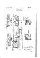
Figure 3, an enlarged view similar to Figure 1 with the stencil removed and disclosing fully the interior of the sign casing;
Figure 4, a section on the line 4-4 of Figure 3; and
Figure 5, a section on the line 5-5 of Figure 3. Y
Referring to the drawings my invention is shown as comprising a metall-ic casing 10 open at the front and provided with a fore and aft partition 11 which divides the interior of the casing into a minor compartment 12 and a major compartment 13. A neon tube 14 is disposed within the casing 10 and extends through the partition 11, so as to dispose one part thereof in the compartment 12 and another part in the compartment 13. That portion of the tube 14 in the compartment 13 is bent to delineate the word Vacant while the 1931.. Serial No. 543,682.
portion in compartment 12 has no particular shape, being utilized solely for the purpose of illuminating a stenciled pane as will hereinafter appear. The open front of the compartment 12 is adapted to be closed by a glass 55 pane on which is suitably stenciled or delineated the name of the company operating the cab. The .pane 15 is held in assembly with the casing 10 by a retaining frame 16 engaged on the casing, said frame having a cross member 17 which overlies the forward edge of the partition 11. When the sign is used for taxicab purposes no closing pane is employed with respect :to the compartment 13. However, when the sign is used for advertising purposes as shown in Figure 2, compartment 13 is closed by a stenciled or delineated glass pane 18 displaying an advertisement, while a separate ypane 19 stenciled or delineated tol indicate the source of the advertisement closes the compartment 12. In either specified use :of my sign the planes 15, 18 and 19 are seated under pressure by the frame 16 against the free ends of rubber bushings 20.which project from the rear wall of the casing 10, such construction being claimed in my copending application Serial'No. 542,999. The mounting of the tube 14 in the casing 10 and the electrical connections therefor are effected in.
a manner similar to that described and so claimed in my aforesaid copending application. Briefly stated, the mounting of the tube is effected by studs 21 projecting from the rear of the casing and to the free ends of which the tube is bound by wires 22. Rubber cushions 23 are interposed between the bottom of the casing 10 and the tube to provide a resilient seat adapted to absorb vibration and assist in preventing breakage. I also further provide against the tube breakage by interposing rubber cushions 24 between the tube and the rear wall of the casing. A post 25 of insulating material is car- Y ried by a side wall of the casing and projects into the compartment 13. This post carries a binding screw 2G which is electrically connected to the adjacent terminal of the tube 14 by a flexible conductor 27. A mounting bracket 28 is secured to the bottom of the casing 10 and through this bracket I lead into ico l 31 through the bracket 28.
the casing a conductor 29 from the high tension terminal of a vibratory coil (not shown). Included in the conductor 29 is a switch 30 through the instrumentality of Which the sign may be extinguished or illuminated as desired. The casing 10 is shown grounded at The terminal of the tube 14 which is located in the compartment 12 is grounded to the casing 10 by a flexible conductor 32 secured at one end to said terminal and at its other end to a bind-v ing screw 33 carried by the casing. It Wil'l of course be understood that when the sign herein described is used in connection With motor vehicles, it is incorporated in the electrical system of such Vehicle in the manner shown in detail in my copending application Serial No. 542,999.
While I have illustrated and described the illuminating element as a neon tube, it Will be apparent that as Jfar as the structure disclosed in Figure 2 is concerned other types of electric illuminating elements may be employed Without any alteration in the casing structure or the delineated panes and their retaining frame.
I claim:
In an electric sign, a casing open at its front, a partition extending fore and aft in the casing and dividing the latter into compartments, a neon tube mounted in the casing and extending through the partition to dispose a part thereof in each compartment, the portion of the tube in one compartment being bent to delineate a sign, a delineated pane closing the other compartment, detachable retaining means for said pane, and means for electrically connecting' theV tube to a source of current.
In testimonyv whereof I hereunto ax my signature;
LOUIS A. KOCH, JB..
Priority Applications (1)
| Application Number | Priority Date | Filing Date | Title |
|---|---|---|---|
| US543682A US1854655A (en) | 1931-06-11 | 1931-06-11 | Electric sign |
Applications Claiming Priority (1)
| Application Number | Priority Date | Filing Date | Title |
|---|---|---|---|
| US543682A US1854655A (en) | 1931-06-11 | 1931-06-11 | Electric sign |
Publications (1)
| Publication Number | Publication Date |
|---|---|
| US1854655A true US1854655A (en) | 1932-04-19 |
Family
ID=24169119
Family Applications (1)
| Application Number | Title | Priority Date | Filing Date |
|---|---|---|---|
| US543682A Expired - Lifetime US1854655A (en) | 1931-06-11 | 1931-06-11 | Electric sign |
Country Status (1)
| Country | Link |
|---|---|
| US (1) | US1854655A (en) |
-
1931
- 1931-06-11 US US543682A patent/US1854655A/en not_active Expired - Lifetime
Similar Documents
| Publication | Publication Date | Title |
|---|---|---|
| US1602094A (en) | Combined vehicle signal, spotlight, and mirror | |
| US1854655A (en) | Electric sign | |
| US1854654A (en) | Electric sign | |
| US2503336A (en) | Traffic signal for vehicles | |
| US2179792A (en) | Indicating device for tail lamps and the like | |
| US2269675A (en) | Illuminated sign for vehicles | |
| US1857916A (en) | Electric sign | |
| US1792599A (en) | Neon-light direction signal | |
| US1509379A (en) | Display device for motor cars | |
| US3071684A (en) | Headlamps | |
| US1655993A (en) | License-plate holder | |
| US2307372A (en) | Motor vehicle signal device | |
| US1304370A (en) | Direction-indicator and mirror | |
| US1506353A (en) | Vehicle direction indicator | |
| US2324419A (en) | Electric traffic signal | |
| US1517318A (en) | Vehicle direction indicator | |
| US2002330A (en) | Wigwag signal | |
| US1960409A (en) | Direction signal | |
| US2345979A (en) | Signaling system | |
| US2173263A (en) | Heating device for windshields of motor vehicles | |
| US2143899A (en) | Traffic signal | |
| US2192712A (en) | Illuminated sign | |
| US1241904A (en) | Direction-indicator for automobiles. | |
| US1564038A (en) | Abraham weiss | |
| US1981302A (en) | Signal light for automotive vehicles |