US1854640A - Means for measuring high electrical potentials - Google Patents
Means for measuring high electrical potentials Download PDFInfo
- Publication number
- US1854640A US1854640A US493730A US49373030A US1854640A US 1854640 A US1854640 A US 1854640A US 493730 A US493730 A US 493730A US 49373030 A US49373030 A US 49373030A US 1854640 A US1854640 A US 1854640A
- Authority
- US
- United States
- Prior art keywords
- spark
- gaps
- potential
- elements
- gap
- Prior art date
- Legal status (The legal status is an assumption and is not a legal conclusion. Google has not performed a legal analysis and makes no representation as to the accuracy of the status listed.)
- Expired - Lifetime
Links
- 239000004020 conductor Substances 0.000 description 16
- VKYKSIONXSXAKP-UHFFFAOYSA-N hexamethylenetetramine Chemical compound C1N(C2)CN3CN1CN2C3 VKYKSIONXSXAKP-UHFFFAOYSA-N 0.000 description 7
- 229920000136 polysorbate Polymers 0.000 description 6
- 230000004044 response Effects 0.000 description 5
- 238000000034 method Methods 0.000 description 3
- BSYNRYMUTXBXSQ-UHFFFAOYSA-N Aspirin Chemical compound CC(=O)OC1=CC=CC=C1C(O)=O BSYNRYMUTXBXSQ-UHFFFAOYSA-N 0.000 description 2
- 230000008859 change Effects 0.000 description 2
- 238000010276 construction Methods 0.000 description 2
- 238000005259 measurement Methods 0.000 description 2
- 230000007246 mechanism Effects 0.000 description 2
- 230000000750 progressive effect Effects 0.000 description 2
- 238000009877 rendering Methods 0.000 description 2
- 102100035683 Axin-2 Human genes 0.000 description 1
- 101700047552 Axin-2 Proteins 0.000 description 1
- 229910001369 Brass Inorganic materials 0.000 description 1
- 238000013459 approach Methods 0.000 description 1
- 239000010951 brass Substances 0.000 description 1
- 238000011161 development Methods 0.000 description 1
- 238000010586 diagram Methods 0.000 description 1
- 239000003989 dielectric material Substances 0.000 description 1
- 238000010892 electric spark Methods 0.000 description 1
- 238000002474 experimental method Methods 0.000 description 1
- 230000001788 irregular Effects 0.000 description 1
- 230000000737 periodic effect Effects 0.000 description 1
- 230000002265 prevention Effects 0.000 description 1
- 229910052705 radium Inorganic materials 0.000 description 1
- HCWPIIXVSYCSAN-UHFFFAOYSA-N radium atom Chemical compound [Ra] HCWPIIXVSYCSAN-UHFFFAOYSA-N 0.000 description 1
- 230000009467 reduction Effects 0.000 description 1
- 239000000126 substance Substances 0.000 description 1
Images

Classifications
-
- G—PHYSICS
- G01—MEASURING; TESTING
- G01R—MEASURING ELECTRIC VARIABLES; MEASURING MAGNETIC VARIABLES
- G01R15/00—Details of measuring arrangements of the types provided for in groups G01R17/00 - G01R29/00, G01R33/00 - G01R33/26 or G01R35/00
- G01R15/14—Adaptations providing voltage or current isolation, e.g. for high-voltage or high-current networks
Definitions
- This invention relates to method-s and rapparatus for measuring high voltages and potentials by means of the electric spark gap.
- the ball spark-gap represents, due to its simplicity, accuracy, freedom from lag and other advantages, one of the most important means for measuring high voltages. These advantages make it also valuable for the measuring of excess potential phenomena.
- the procedure in the measuring by means of the ordinary spark-gaps consists in starting from large rupturing distances, and causing the balls to gradually approach one another until the rupture occurs. rlhis method is, of course, only applicable if the potential to be measured exists for a sufliciently long period, or if the potential impulses'repeat themselves in the same form as often as is necessary in order to be able to adjust the spark-gaps to the limiting sparking distance.
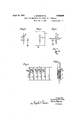
- FIG. l is a diagrammatic view of one form of the invention having recording means
- Fig. 2 is a similar view of another form having recording means
- FIG. 3 is a similar View showing a less elaborate form of the invention.
- Figs. 4 and 5 are schematic diagrams illustrat-ing forces which have to be considered in perfecting this invention.
- Fig. 6 illustrates a preferred form of condenser
- Fig. 7 is a section on the line 7 -7 of Fig. 6;
- Fig. 8 is a side elevation partly in section showing a practical form of condenser.
- the spark gaps F11-#Fg F3, F4, F5, F6 are progressively further apart, the object being to prov1de an -tial distribution.
- the deviation of the proarrangemcnt wliereby a low potential between ,elements a and b will cause sparking at only the shortest gap F1, while a greater potential would cause simultaneous sparking, at a progressively larger number of gaps in proportion to the value of the potential.
- a'ball spark-gap is a condenser of relatively small capacity
- the earth capacity c of the central part d of such an arrangement (shown schematically by Fig. 4) iniuences not inconsiderably the potenportion ofthe potential at the series-connected condenser to the potential a-t the spark-gapof an arrangement with earth capacity of the central part from the potential proportion of the same arrangement but without earth capacity of the; central part, may amount under circumstances to 'several hundred per cent. From this it follows, that such a measuring arrangement with earth capacity of the central part must always be calibrated anew according tothe local conditions. It is furthermore evident that the potential ldistribution over the series-connected condensers and the spark-gaps of such a measuring arrangement is not independent of other external influences, as for instance nei hboring lines carrying a potential.
- the condensers be brid d by high-ohmic resistances R1, R2 y eliminating the condenser at the longest spark-gap F6, this gap serves also as a'protecting spark-gap for the entire measuring apparatus.
- the indivi ual spark-gaps shall re nd without lag.
- 's may be accomplished by using radium Korgother suitable substances.
- the individual spark-gaps are arranged in such a manner that there takes place with u each response a mutual arcing in a progressive manner.
- the spark gap vwith minimum rupturing distancerdoes not act as a measuring spark-gap but acts solely for preparing 'the arcing of the next successive measuring s ark-gap, which latter then again prepares t e arcing of the following one.
- theseries-condensers may be chosen in such manner that the potential component belonging thereto can be neglect/ed with respect to the potential at the spark-gap. This is rendered particularly easy according to the construction of Fig. 3.
- the series-condensers may further be graduated so that the ercenta of their potential component to t at of t e spark-gap is the same in all individual elements.
- a and b designate the connections for the otential to be measured, F the s ark-gaps, the series-connected conensers, G glow-tubes connected in series with a potential source A and connected over partial condensers C with the potential of the series condensers V of the measuring arrangement.
- the potential increase of any series condenser V results in the lighting of the glow-tube G.
- more glow tubes will be lighted in accordance with the number of spark-gaps, which respond in accordance with the potential which occurred.
- the currents flowing through theindividual glow-tubes may act either individuall directly on measurin instruments or ot er indicating devices or indirectly through relays and the like; or, for instance, the entire current of the glowtubes ma take over this function.
- the glowing of the glow-tubes may be interrupted after the lighting, thereby rendering the measuring arran ment again ready vor service.
- the measuring arran ment may be developed, for instance for te measuring of excess-voltages due to lightcent tothe condensers,
- a pair of conducting elements a and b between which the potential difference is to be measured are connected by a plurality of spark gaps, F1, F2, F 3 connected in parallel with each other between said elements, said spark gaps being made progressively longer as shown, or otherwise constructed to give progressively different rupturing values.
- Condensers V1, V2, V3 are interposed between said elements b and the respective spark gaps, the inner element adjacent to the gap being shown as substantially laterally surrounded by the outer element.
- a shunt S is disposed around each con denser, each having a partial capacity C and a glow tube G interposed in series therein, the glow tube being between the capacity and the outer element of the condenser, whereby when rupture takes place, the increasedpotential at the inner element of the condenser will cause current which will cause the glow tube to light up.
- each relay comprising a switch O adapted to close when the associated glow tube lights.
- a common conductor P connects one ter- ⁇ minal of a local source of current Q-to one element of al1 of said switches O; while separate conductors T1, T2, T3 connect the other pole to the other element of therespective switches O.
- Recording devices Z1, Z2, Z3 are interposed in said separate conductors respectively, each device comprising an electromagnet and an armature X carrying a pencil engaging a strip of paper Y moved by a clockwork (not shown).
- the currents flowing through the glowtubes as a result of sparking at the associated spark-gaps cause the relays R to respond, which latter in turn close again the circuits of the battery Q, for the magnet coils of the recording devices Z.
- the relay U connected in the common feeding circuit for the coils of the recording devices operates with a small retardation, and after each rupture interrupts the circuit of the glow-tubes after the number of the glowtubes which responded to the rupture has been correspondingly recorded by the devices Z.
- the relay W connected in the circuit of the switch of the relay R1 of the minimum measuring potential, causes the response of the measuring arrangement to release the detent D of the clock mechanism or other driving mechanism for the paper strip of the recording device to permit the paper to move the same, required distance for each record.
- the apparatus is suitably'surrounded, for reduction of the earth capacity, with a metallic enclosure E which is connected with the conductingelement b.
- Fig. 2 shows, by way of example, another arrangement of the apparatus wherein, from the size of the deflection of an ordinary or recording milliammeter, a deduction may be made as to the value of the excess voltage which occurred; hence, the scale of this instru? ment may be calibrated directlv in kilovolts.
- Fig. 2 the separate conductors, and the common conductor N respectively have interposed therein, a high ohmic resistance H and a self-inductance L to hold back the periodic surges of the high voltages from the recording device.
- the automatic retarder circuit breaker U2 in the com-mon conductor N serves to stop the flow of current through the instrument mA as soon as the latter has reached its maximum roo deection, thus to prepare the apparatus for the next record.
- FIG. 8 A convenient practical form of condenser is shown in Fig. 8 in which a small conducting rod la with rounded end f forms at the same time one element of the spark gap F and the inner element of the condenser V.
- a tube t of dielectric material receives the outer condenser element Vo, in the form of a brass tube.
- Some of the rays of the spark are of such kind as to ionize the air gap ofthe higher value thus facilitatin the arcing of the latt'er in the moment t e voltage reaches the amount the air gap is adjusted for. It has been found by experiments that this arrangement is suicient to get the respective air gaps arcing even if the voltage to be measured exists just for the shortest possible time; as for instance with lightning.
- a pair of elements between which the potential is to be measured means fo a lurality of spark gaps connected inpar lelietween said elements, respective spark gaps having diierent rupturin values, means for indicating the passage o ,s arks across the respective gaps; and a conenser connected in series witheach spark gap and one of said elements.
- a pairs of elements between which the potential is toA be measured in combination, a pairs of elements between which the potential is toA be measured; means forming a plurality of spark gaps connected of said elements; and means for protecting the connectingpart between the condenser and the spark gap against external inlluences, such as earth capacity.
- the condenser element adjacent to the adjacent conductor element substantially surroundin the condenser element adjacent te the spar gaps.
- a pair of elements between which the potential is to be measured means forming a plurality of spark gaps conn in parallel between said elements, respective lspark gaps having different rupturing values, means for indicating the passage o sparks across the respective gaps; and a condenser connected in series with each spark gap and one of said elements, and having its parts so proportioned that the potential component thereof is very small as compared with that of the spark gap.
- a pair of elements between which the potential is to be measured means formin a lurality of spark gaps connected in para lel tween said elements, respective spark gaps having different rupturing values, means for indicating the passage o arks across the respective gaps; and a con enser connected in series between one of said conducting elements and each of said spark gaps except one.
- a pair of elements between which the potential is to be measured means formin a lurality of spark gaps connected in para el tween said elements, respective spark gaps having different rupturing values, means for indicating the passage o sparks across the respective ga s; a condenser connected in series with eac spark gap and one of said elements; and a hi h ohmic resistance shunted around each con enser.
- vIn apparatus for measuring potentials in combination, a air of elements between which the potenti is to be measured; means formin a luralityof spark gaps connected in para lel tween said elements, respective spark gapshaving different rupturing values; condensers one each connecting a spark gap its lll
- indicatin means set in operation by rise in potential tween a condenser and ad'acent spark gap.
- a pair of elements between which the potential is to be measured means formin a plurality of spark gaps connected in para lel between said'elements, respective spark gaps having different rupturing values; a condenser connected in series with each spark gap and one of said elements; and a glow tube set in operation by rise in potential between a condenser and adjacent spark gap- 11.
- a pair of elements between which the potential is to be measured means formin a plurality of spark gaps connected forming a in para lel between said elements, respective spark gaps having different rupturing values; a condenser connected in series with each spark ga and one of said elements;
- a pair of elements between which the potential is to be measured means lurality of spark gaps connected in parallellbetween said elements, respective spark gaps having different. rupturing values; means for indicating the passage of sparks across respective gaps; a condenser connected in series with each s ark gap and one of said-elements; and a g ow' tube and a capacity shunted in series with each other around each condenser.
Landscapes
- Physics & Mathematics (AREA)
- General Physics & Mathematics (AREA)
- Manufacture Of Electron Tubes, Discharge Lamp Vessels, Lead-In Wires, And The Like (AREA)
Description
April 19, 1932. L, BINDER ET AL MEANS FOR MEASURING HIGH ELECTRICAL POTENTIALS Filed Nov. 6, 1930 2 Sheets-Sheet l E. AA QF um UW 2 .k
L). QT n :JJ wk. n. ,M Q u X annuo nl LH T T W, f
V Z --f G2 Calza La y o; @"5 93H4 .L4 1 Al' INVENTOBS anda# e Y idw .my m a Aprily 19, l1932. l.. BINDER ETAI.
MEANS FOR MEYASURING HIGH ELECTRICAL ROTENTALS Filed Nov. 6,. 195o 2 Sheets-Sheet 2 ngi Patented Apr. 19, 1932 UNITED STATES PATENT OFFICE LUDWIG BINDER, or DRESDEN, AND HANS HEYNE, or DRESDEN, BLAsEWITz,
annum MEANS FQR MEASURING HIGH ELECTRICAL POT'ENTIALS Application led November 6, 1930, Serial No. 493,780, and in Germany March 21,` 1928.
l This invention relates to method-s and rapparatus for measuring high voltages and potentials by means of the electric spark gap.
The ball spark-gap represents, due to its simplicity, accuracy, freedom from lag and other advantages, one of the most important means for measuring high voltages. These advantages make it also valuable for the measuring of excess potential phenomena.
The procedure in the measuring by means of the ordinary spark-gaps consists in starting from large rupturing distances, and causing the balls to gradually approach one another until the rupture occurs. rlhis method is, of course, only applicable if the potential to be measured exists for a sufliciently long period, or if the potential impulses'repeat themselves in the same form as often as is necessary in order to be able to adjust the spark-gaps to the limiting sparking distance.
But many excess-voltage phenomena, for linstance those caused by atmospheric discharges, occur only once, o`r in irregular order of succession, so that no possibility is presented for the adjustment by hand of a sparkgap to measure such voltage. Accordingly, we have provided an arrangement in which several spark gaps are connnected in parallel previously ad]usted for various rupturing distances.
Such arrangements are shown in the accompanying drawings, in which Fig. l is a diagrammatic view of one form of the invention having recording means;
Fig. 2 is a similar view of another form having recording means;
Fig. 3 is a similar View showing a less elaborate form of the invention;
Figs. 4 and 5 are schematic diagrams illustrat-ing forces which have to be considered in perfecting this invention;
Fig. 6 illustrates a preferred form of condenser;
Fig. 7 is a section on the line 7 -7 of Fig. 6; and
Fig. 8 is a side elevation partly in section showing a practical form of condenser.
As shown in Figs. l to 3, the spark gaps F11-#Fg F3, F4, F5, F6 are progressively further apart, the object being to prov1de an -tial distribution. The deviation of the proarrangemcnt wliereby a low potential between ,elements a and b will cause sparking at only the shortest gap F1, while a greater potential would cause simultaneous sparking, at a progressively larger number of gaps in proportion to the value of the potential.
lin order to insure that sparking shall not be at only the shortest spark gap, since that ywould immediately cause a. great lowering of the measuring potential, provision is made to damp the sparkI discharges correspondingly. F or instance, in seriesl with the individual spark-gaps are interposed ohmic resistances, choke coils or condensers or combinations thereof.
Of these possibilities preference must beV given to the use of condensers, since, on the one hand, they best fulll the condition, in that they occupy least possible volume and give the largest possible resistance, which is of importance for the constructive development, and since, on the other hand, such an arrangement, respresents in fact a series-connection of a condenser lwith a spark-gap (which is a second condenser), the potential division within this element is independent of the frequency of the measuring potential in periodical phenomena.
Since however, a'ball spark-gap is a condenser of relatively small capacity, the earth capacity c of the central part d, of such an arrangement (shown schematically by Fig. 4) iniuences not inconsiderably the potenportion ofthe potential at the series-connected condenser to the potential a-t the spark-gapof an arrangement with earth capacity of the central part from the potential proportion of the same arrangement but without earth capacity of the; central part, may amount under circumstances to 'several hundred per cent. From this it follows, that such a measuring arrangement with earth capacity of the central part must always be calibrated anew according tothe local conditions. It is furthermore evident that the potential ldistribution over the series-connected condensers and the spark-gaps of such a measuring arrangement is not independent of other external influences, as for instance nei hboring lines carrying a potential.
capacity of the central parts remains con' etant with a change in location of the measuringarran ment. This embodiment is visuahzed in ig. 5 for an element 4of the measuringsarrangement and may of course be apphed correspondingly to the entire measurarrangement. mn the other hand however, the disturbvariable influence of the earth ,capacity of the central part may also b e eliminated by reducing the earth capacity of the middle art d as much as possible. so thatA its inmiluence may be neglected with a change in location of the measuring apparatus. One way, amongst others, of accomplishing this consists in constructing the series-connected condensers so that their outer element encloses the inner element, or at least the central part d, as fully as possible, as is done, by way of example in the cylinder-like construction of the-` outer element Vo of the series-condenser (Figs. 6 and 7 which encloses the inner element d. hereby, the earth capacity of the central (part is shielded or at least suiiiciently reduce A measurin arrangement with several ark-gaps, ad]usted t'o diiferentrupturing distances and constructed with condensers in the shape of cylinders is shown in Fig. 3. For the prevention of errors in measurement due to residual discharges, which perhaps might remain behind in the individual condensers, it is recommended that the condensers be brid d by high-ohmic resistances R1, R2 y eliminating the condenser at the longest spark-gap F6, this gap serves also as a'protecting spark-gap for the entire measuring apparatus.
In order that such a measuring arrangement shall furnish faultless data in case of rapidly and widely var in -voltages, it is Anecessary that the indivi ual spark-gaps shall re nd without lag. As is already known, 's may be accomplished by using radium Korgother suitable substances. However, in accordance with the present invention the individual spark-gaps are arranged in such a manner that there takes place with u each response a mutual arcing in a progressive manner. In this case, the spark gap vwith minimum rupturing distancerdoes not act as a measuring spark-gap but acts solely for preparing 'the arcing of the next successive measuring s ark-gap, which latter then again prepares t e arcing of the following one. A
The 'size of theseries-condensers may be chosen in such manner that the potential component belonging thereto can be neglect/ed with respect to the potential at the spark-gap. This is rendered particularly easy according to the construction of Fig. 3. In this case the series-condensers may further be graduated so that the ercenta of their potential component to t at of t e spark-gap is the same in all individual elements. y
'Ihe progressive increase in the response of the successive individual spark-gaps ma'y be accom lished in various wa s, thus, for instance, in that the individua spark-ga s are adjusted to diierent rupturing lengt s as is shown in Figs. '1 to 3. But, the same result may be obtained by giving the condensers dlfferent sizes -or also by employing both methods simultaneously.
"lVith each response of a spark-gap there is a sudden otential increase of the mentioned centra part d between the gap and the corresponding series-condenser, for the reason that now theentire potential differ' ence practicall goes solely `to said art. This otential increase may now uti ized direct y or indirectly for the release of indicating and recordin devices.
An embodiment uti izing this increase is shown in Fig. 1. As will be explained more fully below a and b designate the connections for the otential to be measured, F the s ark-gaps, the series-connected conensers, G glow-tubes connected in series with a potential source A and connected over partial condensers C with the potential of the series condensers V of the measuring arrangement. With the response of the associa-ted spark-gap the potential increase of any series condenser V results in the lighting of the glow-tube G. Hence, more glow tubes will be lighted in accordance with the number of spark-gaps, which respond in accordance with the potential which occurred.
As will be explained, the currents flowing through theindividual glow-tubes may act either individuall directly on measurin instruments or ot er indicating devices or indirectly through relays and the like; or, for instance, the entire current of the glowtubes ma take over this function. By means of suita le self-breaking relays or other known devices the glowing of the glow-tubes may be interrupted after the lighting, thereby rendering the measuring arran ment again ready vor service. When recor mg instruments are used, the measuring arran ment may be developed, for instance for te measuring of excess-voltages due to lightcent tothe condensers,
ning'by the corresponding use of a further relay, in such manner that a releasing device of the recording instrument is released by said rela-y, so that the first occurring excess potential automatically puts the entire measuring arrangement in operation.
In the apparatus of Fig. 1, a pair of conducting elements a and b between which the potential difference is to be measured are connected by a plurality of spark gaps, F1, F2, F 3 connected in parallel with each other between said elements, said spark gaps being made progressively longer as shown, or otherwise constructed to give progressively different rupturing values.
Condensers V1, V2, V3 are interposed between said elements b and the respective spark gaps, the inner element adjacent to the gap being shown as substantially laterally surrounded by the outer element.
A shunt S is disposed around each con denser, each having a partial capacity C and a glow tube G interposed in series therein, the glow tube being between the capacity and the outer element of the condenser, whereby when rupture takes place, the increasedpotential at the inner element of the condenser will cause current which will cause the glow tube to light up.
individual conductors M1, M2, M3, conneet one end of a source of potential A to a point of the respective shunts S between the glow tube and the capacity C. A common conductor N connects the other end of said source to the conductin element adjal whereby when a glow tube lights up current may pass through its associated individual conductors M. Relays R1, R2, R3 are interposed in the respective individual conductors, each relay comprising a switch O adapted to close when the associated glow tube lights.
A common conductor P connects one ter- `minal of a local source of current Q-to one element of al1 of said switches O; while separate conductors T1, T2, T3 connect the other pole to the other element of therespective switches O.
Recording devices Z1, Z2, Z3 are interposed in said separate conductors respectively, each device comprising an electromagnet and an armature X carrying a pencil engaging a strip of paper Y moved by a clockwork (not shown).
When rupture takes place at any spark gap, current passes through lthe associated relay and recording device magnet, causing the pencil to make a mark upon the paper Y. If rupture takes place at one or more gaps it will take place at the shortest gap- F1; and a releasing magnet W interposed in the branch 1conductor T1 associated with the smallestgap F1 will be ener ized and draw an armature E, connected wit a detent D of the clockwork, whereby whenever any rupture takes place,'the clockwork will be caused to move the record strip one space for the next record.
A retarded relay U having its magnet interposed in the common conductor P of the local source, acts to open a switch K in the main Conductor, thereby stopping current through the glow tubes, releasing the associated relays and rendering the recording devices ready for the next measurement.
The currents flowing through the glowtubes as a result of sparking at the associated spark-gaps cause the relays R to respond, which latter in turn close again the circuits of the battery Q, for the magnet coils of the recording devices Z. The relay U, connected in the common feeding circuit for the coils of the recording devices operates with a small retardation, and after each rupture interrupts the circuit of the glow-tubes after the number of the glowtubes which responded to the rupture has been correspondingly recorded by the devices Z.
The relay W, connected in the circuit of the switch of the relay R1 of the minimum measuring potential, causes the response of the measuring arrangement to release the detent D of the clock mechanism or other driving mechanism for the paper strip of the recording device to permit the paper to move the same, required distance for each record.
The apparatus is suitably'surrounded, for reduction of the earth capacity, with a metallic enclosure E which is connected with the conductingelement b.
Fig. 2 shows, by way of example, another arrangement of the apparatus wherein, from the size of the deflection of an ordinary or recording milliammeter, a deduction may be made as to the value of the excess voltage which occurred; hence, the scale of this instru? ment may be calibrated directlv in kilovolts.
.lin Fig. 2, the'elements a, b, the gaps F, the condensers V, and glow tubes G, the source A, the releasing magnet W and detent D are the same as in Fig. 1.
But in Fig. 2, the separate conductors, and the common conductor N respectively have interposed therein, a high ohmic resistance H and a self-inductance L to hold back the periodic surges of the high voltages from the recording device. A milliammeter or similar instrument mA connected in the common feeding conductor N from the source A to the glow tubes G, hence shows a deflection which is the larger the greater the current consumption, that is, which is larger when more glow-tubes are lighted and spark-gaps have responded, hence the greater in proportion to the excess voltage which has occurred.
The automatic retarder circuit breaker U2 in the com-mon conductor N serves to stop the flow of current through the instrument mA as soon as the latter has reached its maximum roo deection, thus to prepare the apparatus for the next record.
A convenient practical form of condenser is shown in Fig. 8 in which a small conducting rod la with rounded end f forms at the same time one element of the spark gap F and the inner element of the condenser V. A tube t of dielectric material receives the outer condenser element Vo, in the form of a brass tube. Y
In order to get correct indications or records of the apparatus above described, even with very 'quick henomena, as 1i htning etc., it is necessary t at the arc1n o the res ctiv'e air gap takes place wi out any de ay. This will attained by pre-ionizing each of the measuring air gaps in acertam degrec. For this reason we have arranged the air gaps so near each other that the spark of each air gap (except the largest). will illuminate the a1r gap of the next higher value. Some of the rays of the spark are of such kind as to ionize the air gap ofthe higher value thus facilitatin the arcing of the latt'er in the moment t e voltage reaches the amount the air gap is adjusted for. It has been found by experiments that this arrangement is suicient to get the respective air gaps arcing even if the voltage to be measured exists just for the shortest possible time; as for instance with lightning.
We claim as our Invention:
1. In apparatus for measuring potentials, in combination, a pair of elements between which the potential is to be measured; means formin a lurality of spark gaps connected in para e1 tween said elements, respective spark gaps having different predetermined rupturlng values, and means for indicating the passage of sparks across the respective ps. 1 2. In apparatus for measuring potentials, in combination, a pair of elements between which the potential is tobe measured; means formin a lurality of spark gaps connected in para el tween said elements, respective spark gaps having dierent rupturing values, means for indicating the passage of sparks across the respective gaps; and means.
for protecting the apparatus against external lnluences.
3. In apparatus for measuring potentials, in combination, a pair of elements between which the potential is to be measured; means fo a lurality of spark gaps connected inpar lelietween said elements, respective spark gaps having diierent rupturin values, means for indicating the passage o ,s arks across the respective gaps; and a conenser connected in series witheach spark gap and one of said elements.
" 4. In'apparatus for measuring potentials,
in combination, a pairs of elements between which the potential is toA be measured; means forming a plurality of spark gaps connected of said elements; and means for protecting the connectingpart between the condenser and the spark gap against external inlluences, such as earth capacity.
5. In apparatus for measuring potentials,
nected in series with eac spark gap and one 7 in combination, a pair of conductor elements between which ythe potential is to be measured; means forming a plurality of (slpark gaps connected in paralle between sai elements, respective spark gaps having different s rupturing values, means for indicati the passage of sparks across the respective gaps;
and a condenser connected in series with each spark gap and one of said conductor elements; the condenser element adjacent to the adjacent conductor element substantially surroundin the condenser element adjacent te the spar gaps.
6. In apparatus for measuring potentials, in combination, a pair of elements between which the potential is to be measured; means forming a plurality of spark gaps conn in parallel between said elements, respective lspark gaps having different rupturing values, means for indicating the passage o sparks across the respective gaps; and a condenser connected in series with each spark gap and one of said elements, and having its parts so proportioned that the potential component thereof is very small as compared with that of the spark gap.
7. In apparatus for measuring potentials, in combination, a pair of elements between which the potential is to be measured; means formin a lurality of spark gaps connected in para lel tween said elements, respective spark gaps having different rupturing values, means for indicating the passage o arks across the respective gaps; and a con enser connected in series between one of said conducting elements and each of said spark gaps except one.
8. In apparatus for measuring potentials, in combination, a pair of elements between which the potential is to be measured; means formin a lurality of spark gaps connected in para el tween said elements, respective spark gaps having different rupturing values, means for indicating the passage o sparks across the respective ga s; a condenser connected in series with eac spark gap and one of said elements; and a hi h ohmic resistance shunted around each con enser.
9. vIn apparatus for measuring potentials, in combination, a air of elements between which the potenti is to be measured; means formin a luralityof spark gaps connected in para lel tween said elements, respective spark gapshaving different rupturing values; condensers one each connecting a spark gap its lll
to one of said elements; and indicatin means set in operation by rise in potential tween a condenser and ad'acent spark gap.
10. In apparatus or measuring potentials, in combination, a pair of elements between which the potential is to be measured; means formin a plurality of spark gaps connected in para lel between said'elements, respective spark gaps having different rupturing values; a condenser connected in series with each spark gap and one of said elements; and a glow tube set in operation by rise in potential between a condenser and adjacent spark gap- 11. In apparatus for measuring potentials, in combination, a pair of elements between which the potential is to be measured; means formin a plurality of spark gaps connected forming a in para lel between said elements, respective spark gaps having different rupturing values; a condenser connected in series with each spark ga and one of said elements;
and a glow tu e shunted around'each condenser.
12. In apparatus for measuring potentials, in combination, a pair of elements between which the potential is to be measured; means lurality of spark gaps connected in parallellbetween said elements, respective spark gaps having different. rupturing values; means for indicating the passage of sparks across respective gaps; a condenser connected in series with each s ark gap and one of said-elements; and a g ow' tube and a capacity shunted in series with each other around each condenser.
21st of October .D. 1930.
LUDWIG BINDER. HANS HEYNE.
Sined at Dresden Saxony, Germany, this
Applications Claiming Priority (1)
| Application Number | Priority Date | Filing Date | Title |
|---|---|---|---|
| DE1854640X | 1928-03-21 |
Publications (1)
| Publication Number | Publication Date |
|---|---|
| US1854640A true US1854640A (en) | 1932-04-19 |
Family
ID=7746146
Family Applications (1)
| Application Number | Title | Priority Date | Filing Date |
|---|---|---|---|
| US493730A Expired - Lifetime US1854640A (en) | 1928-03-21 | 1930-11-06 | Means for measuring high electrical potentials |
Country Status (1)
| Country | Link |
|---|---|
| US (1) | US1854640A (en) |
Cited By (2)
| Publication number | Priority date | Publication date | Assignee | Title |
|---|---|---|---|---|
| US2665607A (en) * | 1945-07-21 | 1954-01-12 | Bristol Company | Cloud-data recorder |
| US2817815A (en) * | 1948-02-02 | 1957-12-24 | Thomas P Evans | Transient signal recorder |
-
1930
- 1930-11-06 US US493730A patent/US1854640A/en not_active Expired - Lifetime
Cited By (2)
| Publication number | Priority date | Publication date | Assignee | Title |
|---|---|---|---|---|
| US2665607A (en) * | 1945-07-21 | 1954-01-12 | Bristol Company | Cloud-data recorder |
| US2817815A (en) * | 1948-02-02 | 1957-12-24 | Thomas P Evans | Transient signal recorder |
Similar Documents
| Publication | Publication Date | Title |
|---|---|---|
| US1744840A (en) | Voltage-indicating and translating device | |
| US2094645A (en) | Voltage indicating device | |
| US1854640A (en) | Means for measuring high electrical potentials | |
| US2010189A (en) | Means for testing metals | |
| Anderson et al. | The propasation mechanism of impulse creepage discharges over oil-immersed surfaces | |
| Hagenguth et al. | Sixty-Cycle and Impulse Sparkover of Large Gap Spacings [includes discussion] | |
| US2188588A (en) | Resistance and impedance measuring device | |
| US2669004A (en) | Varistor curve tracer | |
| US1945263A (en) | Apparatus for testing insulating values | |
| US2457892A (en) | Pulse testing equipment | |
| US2324835A (en) | Impulse tester | |
| US1795176A (en) | Capacitance connection to high-voltage lines | |
| US2673957A (en) | Shunt for low-voltage circuit testers | |
| US2871365A (en) | Apparatus for detecting radioactivity | |
| Foust | instruments for Lightning Measurements | |
| US2838679A (en) | Circuit for measuring radiation intensities | |
| US1645057A (en) | Thermionic current transformer | |
| US3246237A (en) | Apparatus for detecting discharges in insulation and for discriminating between suchdischarges and any discharges occurring in termination means carried by such insulation | |
| US2941143A (en) | Voltage responsive apparatus | |
| US2521917A (en) | Micrometer | |
| US1796637A (en) | Potential-indicating device for signaling systems | |
| US1759604A (en) | Indicating device | |
| US478098A (en) | evershed | |
| US1973870A (en) | Spark plug tester | |
| Dunlap | The recovery-voltage analyzer for determination of circuit recovery characteristics |