US1854636A - Attachment for motor vehicle wheels - Google Patents
Attachment for motor vehicle wheels Download PDFInfo
- Publication number
- US1854636A US1854636A US293853A US29385328A US1854636A US 1854636 A US1854636 A US 1854636A US 293853 A US293853 A US 293853A US 29385328 A US29385328 A US 29385328A US 1854636 A US1854636 A US 1854636A
- Authority
- US
- United States
- Prior art keywords
- disk
- wheel
- segment
- attachment
- motor vehicle
- Prior art date
- Legal status (The legal status is an assumption and is not a legal conclusion. Google has not performed a legal analysis and makes no representation as to the accuracy of the status listed.)
- Expired - Lifetime
Links
- 230000000284 resting effect Effects 0.000 description 4
- 230000004075 alteration Effects 0.000 description 1
- 238000010276 construction Methods 0.000 description 1
- 230000004048 modification Effects 0.000 description 1
- 238000012986 modification Methods 0.000 description 1
- 238000005096 rolling process Methods 0.000 description 1
- 239000007787 solid Substances 0.000 description 1
Images

Classifications
-
- B—PERFORMING OPERATIONS; TRANSPORTING
- B60—VEHICLES IN GENERAL
- B60B—VEHICLE WHEELS; CASTORS; AXLES FOR WHEELS OR CASTORS; INCREASING WHEEL ADHESION
- B60B11/00—Units comprising multiple wheels arranged side by side; Wheels having more than one rim or capable of carrying more than one tyre
- B60B11/02—Units of separate wheels mounted for independent or coupled rotation
-
- B—PERFORMING OPERATIONS; TRANSPORTING
- B60—VEHICLES IN GENERAL
- B60B—VEHICLE WHEELS; CASTORS; AXLES FOR WHEELS OR CASTORS; INCREASING WHEEL ADHESION
- B60B11/00—Units comprising multiple wheels arranged side by side; Wheels having more than one rim or capable of carrying more than one tyre
- B60B11/10—Emergency wheels
-
- B—PERFORMING OPERATIONS; TRANSPORTING
- B60—VEHICLES IN GENERAL
- B60B—VEHICLE WHEELS; CASTORS; AXLES FOR WHEELS OR CASTORS; INCREASING WHEEL ADHESION
- B60B2900/00—Purpose of invention
- B60B2900/70—Adaptation for
- B60B2900/731—Use in cases of damage, failure or emergency
-
- Y—GENERAL TAGGING OF NEW TECHNOLOGICAL DEVELOPMENTS; GENERAL TAGGING OF CROSS-SECTIONAL TECHNOLOGIES SPANNING OVER SEVERAL SECTIONS OF THE IPC; TECHNICAL SUBJECTS COVERED BY FORMER USPC CROSS-REFERENCE ART COLLECTIONS [XRACs] AND DIGESTS
- Y10—TECHNICAL SUBJECTS COVERED BY FORMER USPC
- Y10T—TECHNICAL SUBJECTS COVERED BY FORMER US CLASSIFICATION
- Y10T292/00—Closure fasteners
- Y10T292/08—Bolts
- Y10T292/0801—Multiple
- Y10T292/0834—Sliding
- Y10T292/0836—Operating means
- Y10T292/0839—Link and lever
Definitions
- This invention relates to new and useful improvements in attachments for motor vehicle wheels. j
- One object of the invention is to provide an improved attachment which may be readily and easily secured to a motor vehicle wheel.
- Another object of the invention is to provide means for quickly and easily fastening the attachment to the wheel together with means for automatically centering the at tachment on said wheel.
- Fig. 1 is an elevation of a wheel attachment constructed in accordance with the invention
- Fig. 2 is a partial view of the same showing the lugs unlocked
- I Fig. 3 is an elevation showing the device attached to a wheel having a deflated tire
- Fig. 4 is a vertical sectional view of the I
- the numeral 10 designates a disk or circular plate having a segment 11 out therefrom.
- the disk and the segment provide a circular support and said parts are formed with an outwardly directed circumferential flange 12 which may be grooved for 1928.
- the disk without a tire or with a tire should have an over-all diameter greater than the tire 13 of the wheel l lwith which it is automatically centering the disk on the wheel.
- the disk has a central opening 17. for receiving the hub of the vehicle wheel.
- each lug 18 For securing the disk to the wheel a pair of lugs 18 are bolted to the inner side of the disk and each lug has a saddle 19 for engaging the felly of the wheel 14. These lugs are placed on the lower half of the disk and on the upper half a pair of sliding lugs 21 are mounted and formed with saddles 22 for receiving the felly 20.
- Each lug 21 has a shank 23 extending through a radial slot in the disk and pivoted to the outer end of a link 25.
- the links 25 are pivoted on the opposite sides of the center of a small locking wheel 26 having an operating lever 27 extending therefrom.
- This wheel is pivoted on a stud 27 set to one side of the vertical center of the disk which causes one link 25 to be shorter than the other.
- the lever 27 When the lever 27 is shifted to the left, as is shown in Fig. 2, the wheel 26 will be rotated so as to move the links toward each other and thus slide the shanks 23 to the bottoms of the slots 24, thereby withdrawing the saddles 22 from the felly.
- the lever When the lever is shifted to the right, as is shown in Fig. 1, the links will be spread and the lugs 21 moved outwardly so as to engage their saddles 22 with the felly and thereby lock the disk on the wheel 14.
- hinge members 28 are fastened to the disk and provided with straps 29 fastened to the segment.
- a coiled spring 30 is provided wlth a loop 31 engaging the segment and hinged in brackets 32 on the disk proper.
- spring latches 33 are mounted on the segment. Each latch is provided with a spring pressed plunger 35 which engages a keeper 34 on the disk.
- the lugs 21 being withdrawn pass between the spokes of the wheel and by shifting the lever 27 to the right from the position shown in Fig. 2, to the position shown in Fig. 1, the lugs 21 are moved outwardly so that their saddles'22- engage the telly and lock the disk thereon.
- the atachment is easily and quickly ap plied and it is not necessary to use a wrench or other tools. It is obvious that as soon as the vehicle is moved forward to partially rotate the disk, whereby the segment is lifted from the ground, the spring loop 31 will swing said segment into the plane of the disk, thus obviating the use of a jack or other means to apply and center the attachment. When the segment swings into place the latches 33 will automatically engage with the keepers 3a and the attaching operation is thus completed. The device may be quickly detached or may remain on the wheel as long as is desired.
- a c rcular supporting member having a portion movable from its place to permit said member to be concentrically attached to awheel resting upon a deflated tire, said mov- Y able portion being permanently attached to the member, and means for automatically swinging the said portion into the plane of the member when the wheel is rotated.
- a clrcular supporting disk having a hinged segment, means for securing the disk to a vehicle wheel with the segment displaced laterally from the plane of the disk, and means for swinging the segment into the plane of the disk when the wheel is rotated.
- a circular supporting disk having a hinged segment, means for securing the disk to a vehicle wheel with the segment displaced laterally from the plane ofthe disk, means for swinging the segment into the plane of the disk when the'wheel is rotated, andmeans for fastening the segment in position.
- a circular supporting member having a hinged section less than half its diameter, means for centering the member on a vehicle wheel when the latter is resting on a deflated tire, means for fastening the member to a vehicle wheel, and means for automatically swinging the hinged section into the plane of the member when the wheel is rotated.
- circular supporting member having a hinged section less than half its diameter, means for centering the member on a vehicle wheel when the latter is resting on a deflated tire, means for fastening the member to a vehicle wheel, means for automatically swinging the hinged section into the plane of the member when the wheel is rotated, and means for fastening the section in position.
- a circular disk In a motor vehiclewheel attachment, a circular disk, a centering ring on the inner side of the disk, stationary lugs on the disk for engaging the telly of a wheel, a plurality of movable lugs on the disk for engaging the telly of a wheel to fasten the disk thereon, and means operating the movable lugs in common.
- a circular disk In a motor vehicle wheel attachment, a circular disk, a centering ring on the inner side of the disk, stationary lugs on the disk for engaging the telly of a wheel, movable lugs on the disk for engaging the telly of a wheel to fasten the disk thereon, an operating member pivoted on the disk, and links pivotally connecting the movable lugs with the operating member- 8.
- a circular disk having a hinged segment, a
- a circular supporting member having a portion of its periphery attached thereto for movement .from the plane of the member to permit the same to be concentrically attached to a wheel resting upon a deflated tire, and means for automatically moving said portion into said plane to restore the circular outline of said member.
- a rotary jack and auxiliary wheel for vehicle wheels or the like said auxiliary wheel being composed of two segments of unequal sizes, a pivotal connection between said segments permitting said smaller segment to swing laterally relative to said larger segment, spring means yieldingly holding said smaller segment in one extreme position, means for securing said larger segment to one of the vehicle wheels whereby upon horizontal movement of said vehicle, said vehicle rides up on the said larger segment, and means for locking said smaller segment in circular relation to said larger segment.
- An emergency tire for an automobile wheel comprising a ring for disposition at one side of the wheel and provided with a tread portion, said ring and its tread portion being transversely split into two arcuate sections, and axially alined means hinging said sections together, one of said sections being of considerably greater length than the other, whereby after securing said one section to a wheel and rolling the latter to dispose said one section against the roadway, said other section will be free of contact with said roadway and may be readily swung to operative position.
Landscapes
- Engineering & Computer Science (AREA)
- Mechanical Engineering (AREA)
- Tires In General (AREA)
Description
A ril 19, 1932. E. WESTBROOK ET AL 1,854,636
ATTACHMENT FOR MOTOR VEHICLE WHEELS Filed July 19, 1928 2 Sheets-Sheet l gmento'z v Zar/ .h /esf'br'ook I George Eivbha A ril 19, 1932- E. WESTBROOK ET AL ATTACHMENT FOR MOTOR VEHICLE WHEELS 2 Sheets-Sheet 2 Filed July 19, 1928 7 3' dr/ Wes/ bra Gear-q; 5E, EYOWS.
I'll
. Patented Apr. 19, 1932 UNITED STATES,
PATENT OFFICE EARL WESTBROOK AND GEORGE E. EVANS, OF NEAR WACO,.TEXAS; SAID EVANS AS- SIGNOB, BY MESNE ASSIGNMENTS, T HARRY E. NEHIN, OF BUFFALO, NEW YORK ATTACHMENT FOR MOTOR VEHICELE WHEELS Application filed July 19,
This invention relates to new and useful improvements in attachments for motor vehicle wheels. j
One object of the invention is to provide an improved attachment which may be readily and easily secured to a motor vehicle wheel.
tinuous circular support for the wheel when the vehicle is driven forwardly.
Another object of the invention is to provide means for quickly and easily fastening the attachment to the wheel together with means for automatically centering the at tachment on said wheel.
A construction designed to carry out the invention will be hereinafter described, to-
gether with other features of the invention.
The invention will be more readily understood from a reading of the following specification and by reference to the accompanying drawings, in which an example ofthe invention is shown, and wherein:
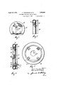
Fig. 1 is an elevation of a wheel attachment constructed in accordance with the invention,
Fig. 2 is a partial view of the same showing the lugs unlocked,
I Fig. 3 is an elevation showing the device attached to a wheel having a deflated tire,
Fig. 4: is a vertical sectional view of the I In the drawings the numeral 10 designates a disk or circular plate having a segment 11 out therefrom. The disk and the segment provide a circular support and said parts are formed with an outwardly directed circumferential flange 12 which may be grooved for 1928. Serial No. 293,853.
receiving a solid rubber or other tire (not shown) The disk without a tire or with a tire should have an over-all diameter greater than the tire 13 of the wheel l lwith which it is automatically centering the disk on the wheel.
The disk has a central opening 17. for receiving the hub of the vehicle wheel.
For securing the disk to the wheel a pair of lugs 18 are bolted to the inner side of the disk and each lug has a saddle 19 for engaging the felly of the wheel 14. These lugs are placed on the lower half of the disk and on the upper half a pair of sliding lugs 21 are mounted and formed with saddles 22 for receiving the felly 20. Each lug 21 has a shank 23 extending through a radial slot in the disk and pivoted to the outer end of a link 25. The links 25 are pivoted on the opposite sides of the center of a small locking wheel 26 having an operating lever 27 extending therefrom.
This wheel is pivoted on a stud 27 set to one side of the vertical center of the disk which causes one link 25 to be shorter than the other. When the lever 27 is shifted to the left, as is shown in Fig. 2, the wheel 26 will be rotated so as to move the links toward each other and thus slide the shanks 23 to the bottoms of the slots 24, thereby withdrawing the saddles 22 from the felly. When the lever is shifted to the right, as is shown in Fig. 1, the links will be spread and the lugs 21 moved outwardly so as to engage their saddles 22 with the felly and thereby lock the disk on the wheel 14.
It is obvious that when the tire 13 is punctured or deflated and the wheel 14 thus lowered, it would be impossible to concentrically fasten the disk on the wheel and to permit this the segment 11 is hinged to the body of the disk and swung outwardly, as is shown in Fig. 3. In carrying out this feature hinge members 28 are fastened to the disk and provided with straps 29 fastened to the segment. In
order to swing the segment into the plane of the disk, a coiled spring 30 is provided wlth a loop 31 engaging the segment and hinged in brackets 32 on the disk proper. For holding the segment in the plane of the disk, spring latches 33 are mounted on the segment. Each latch is provided with a spring pressed plunger 35 which engages a keeper 34 on the disk. When the latches are disengaged from the keepers, the segment may be swung outwardly, as is shown in Figs. 3 and i.
In using the attachment it will be assumed that the tire 13 is punctured or deflated, as is shown in Fig. 3. When it is desired to attach the device, the lever 27 is swung to the position shown in Fig. 2 and the latches 33 are disengaged so that the segment 11 may be swung outwardly, as is shown in Figs. 3 and at. The segment will rest upon the ground when the disk 10 is presented to the wheel 14. The operator engages the saddles 19 of the lower lugs 18 on the telly 20 at the bottom of the wheel and swings the ring 15 intothe rim 16, whereby the disk is automatically positioned concentrically on the wheel let. The lugs 21 being withdrawn pass between the spokes of the wheel and by shifting the lever 27 to the right from the position shown in Fig. 2, to the position shown in Fig. 1, the lugs 21 are moved outwardly so that their saddles'22- engage the telly and lock the disk thereon.
The atachment is easily and quickly ap plied and it is not necessary to use a wrench or other tools. It is obvious that as soon as the vehicle is moved forward to partially rotate the disk, whereby the segment is lifted from the ground, the spring loop 31 will swing said segment into the plane of the disk, thus obviating the use of a jack or other means to apply and center the attachment. When the segment swings into place the latches 33 will automatically engage with the keepers 3a and the attaching operation is thus completed. The device may be quickly detached or may remain on the wheel as long as is desired.
Various changes in the size and shape of the different parts, as well as modifications and alterations, may be made within the scope of the appended claims.
What we claim, is:
1. In a motor vehicle wheel attachment, a c rcular supporting member having a portion movable from its place to permit said member to be concentrically attached to awheel resting upon a deflated tire, said mov- Y able portion being permanently attached to the member, and means for automatically swinging the said portion into the plane of the member when the wheel is rotated.
2. In a motor vehicle wheel attachment, a clrcular supporting disk having a hinged segment, means for securing the disk to a vehicle wheel with the segment displaced laterally from the plane of the disk, and means for swinging the segment into the plane of the disk when the wheel is rotated.
3. In a motor vehicle'wheel attachment, a circular supporting disk having a hinged segment, means for securing the disk to a vehicle wheel with the segment displaced laterally from the plane ofthe disk, means for swinging the segment into the plane of the disk when the'wheel is rotated, andmeans for fastening the segment in position.
4. In a motor vehicle wheel attachment, a circular supporting member having a hinged section less than half its diameter, means for centering the member on a vehicle wheel when the latter is resting on a deflated tire, means for fastening the member to a vehicle wheel, and means for automatically swinging the hinged section into the plane of the member when the wheel is rotated.
5. In a motor vehicle wheel attachment, a
circular supporting member having a hinged section less than half its diameter, means for centering the member on a vehicle wheel when the latter is resting on a deflated tire, means for fastening the member to a vehicle wheel, means for automatically swinging the hinged section into the plane of the member when the wheel is rotated, and means for fastening the section in position.
6. In a motor vehiclewheel attachment, a circular disk, a centering ring on the inner side of the disk, stationary lugs on the disk for engaging the telly of a wheel, a plurality of movable lugs on the disk for engaging the telly of a wheel to fasten the disk thereon, and means operating the movable lugs in common.
7. In a motor vehicle wheel attachment, a circular disk, a centering ring on the inner side of the disk, stationary lugs on the disk for engaging the telly of a wheel, movable lugs on the disk for engaging the telly of a wheel to fasten the disk thereon, an operating member pivoted on the disk, and links pivotally connecting the movable lugs with the operating member- 8. In a motor vehicle wheel attachment, a circular disk having a hinged segment, a
' spring actuated loop mounted on the disk and engaging the segment, latches on the disk for fastening the segment in the vertical plane thereof, and means on the disk for securing the same to a vehicle wheel.
9. In a vehicle wheel attachment, a circular supporting member having a portion of its periphery attached thereto for movement .from the plane of the member to permit the same to be concentrically attached to a wheel resting upon a deflated tire, and means for automatically moving said portion into said plane to restore the circular outline of said member.
10. A rotary jack and auxiliary wheel for vehicle wheels or the like, said auxiliary wheel being composed of two segments of unequal sizes, a pivotal connection between said segments permitting said smaller segment to swing laterally relative to said larger segment, spring means yieldingly holding said smaller segment in one extreme position, means for securing said larger segment to one of the vehicle wheels whereby upon horizontal movement of said vehicle, said vehicle rides up on the said larger segment, and means for locking said smaller segment in circular relation to said larger segment.
11. An emergency tire for an automobile wheel comprising a ring for disposition at one side of the wheel and provided with a tread portion, said ring and its tread portion being transversely split into two arcuate sections, and axially alined means hinging said sections together, one of said sections being of considerably greater length than the other, whereby after securing said one section to a wheel and rolling the latter to dispose said one section against the roadway, said other section will be free of contact with said roadway and may be readily swung to operative position. I
In testimony whereof we affix our signatures.
EARL WESTBROOK. GEORGE E. EVANS.
Priority Applications (1)
| Application Number | Priority Date | Filing Date | Title |
|---|---|---|---|
| US293853A US1854636A (en) | 1928-07-19 | 1928-07-19 | Attachment for motor vehicle wheels |
Applications Claiming Priority (1)
| Application Number | Priority Date | Filing Date | Title |
|---|---|---|---|
| US293853A US1854636A (en) | 1928-07-19 | 1928-07-19 | Attachment for motor vehicle wheels |
Publications (1)
| Publication Number | Publication Date |
|---|---|
| US1854636A true US1854636A (en) | 1932-04-19 |
Family
ID=23130864
Family Applications (1)
| Application Number | Title | Priority Date | Filing Date |
|---|---|---|---|
| US293853A Expired - Lifetime US1854636A (en) | 1928-07-19 | 1928-07-19 | Attachment for motor vehicle wheels |
Country Status (1)
| Country | Link |
|---|---|
| US (1) | US1854636A (en) |
Cited By (3)
| Publication number | Priority date | Publication date | Assignee | Title |
|---|---|---|---|---|
| US2513584A (en) * | 1945-05-18 | 1950-07-04 | Arthur M O'leary | Coupling fixture for pneumatic tire wheels |
| US3295894A (en) * | 1965-04-23 | 1967-01-03 | Walter L Reardon | Auxiliary automobile wheel support |
| US3679267A (en) * | 1970-08-14 | 1972-07-25 | Octave B Zachmann | Spare wheel for automobile |
-
1928
- 1928-07-19 US US293853A patent/US1854636A/en not_active Expired - Lifetime
Cited By (3)
| Publication number | Priority date | Publication date | Assignee | Title |
|---|---|---|---|---|
| US2513584A (en) * | 1945-05-18 | 1950-07-04 | Arthur M O'leary | Coupling fixture for pneumatic tire wheels |
| US3295894A (en) * | 1965-04-23 | 1967-01-03 | Walter L Reardon | Auxiliary automobile wheel support |
| US3679267A (en) * | 1970-08-14 | 1972-07-25 | Octave B Zachmann | Spare wheel for automobile |
Similar Documents
| Publication | Publication Date | Title |
|---|---|---|
| US2505172A (en) | Tire-changing stand with a rotatable tool supporting shaft | |
| US1854636A (en) | Attachment for motor vehicle wheels | |
| US2515167A (en) | Universal tire supporting carrier | |
| US3239277A (en) | Traction structure for motor vehicles | |
| US3850216A (en) | Tire attachment for traction on ice or snow | |
| US2655985A (en) | Circumferentially traveling support-mounted tire mounting apparatus | |
| US2770280A (en) | Anti-skid apparatus for motor vehicles | |
| US2502060A (en) | Emergency wheel for vehicles | |
| US1823660A (en) | Rotary lifting jack and wheel | |
| US2617689A (en) | Emergency wheel | |
| US1498107A (en) | Wheel attachment | |
| US2437811A (en) | Emergency tire carrier | |
| US2535567A (en) | Auxiliary wheel for motor vehicles | |
| US2148111A (en) | Tire tool | |
| US1433279A (en) | howell | |
| US1419531A (en) | Carrier and retractor for wheel rims and tires | |
| US1878213A (en) | Metal wheel | |
| US1813391A (en) | Antiskid device | |
| US1526060A (en) | Attachment for deflated pneumatically-tired vehicle wheels | |
| US2031257A (en) | Emergency wheel | |
| US2906322A (en) | Circumferentially traveling type tire mounting device | |
| US1095451A (en) | Non-slip attachment for vehicle-wheels. | |
| US1142350A (en) | Vehicle-wheel with demountable rim. | |
| US1498369A (en) | Tire mounting | |
| US1274863A (en) | Demountable wheel-rim. |